
Operation Manual


11
ENGLISH
4. START-UP OF THE HEAT PUMP
4.1. Installation rules
It is necessary to determine the unit location according to certain criteria:
The unit must be secured on a hard base (concrete or hard steel frame type) and must be protected from flood
risks
The unit must be installed outside, far away from the sun’s direct rays and any other heat source.
A clear space around the unit of around 1 m at the front and a minimum of 0.5 m at the back and sides of the unit
must be left.
The air caused by the helix must be directed away from the limits of the work environment (windows, doors...).
The minimum distance between the heat pump and the rim of the swimming pool must be, at least, 3.5 m.
(Electrical Regulations for Low Voltage, Supplementary Technical Instructions, Low Voltage, 31, ITC-BT-31).
The electrical and hydraulic connections must be made according to the applicable regulations (NF C 15 100, EC
1364). The ducting for the connections must be fixed.
During operation of the equipment, it is normal that the condensation produced by the evaporation unit will
produce a certain quantity of water which will have to be evacuated.
This condensation water does not have to be treated in any special manner.
Do not install the pump close to place where a big amount of water could reach the machine. Ceilings and water
conduits could forward rain water that mixed with other solid materials could damage the heat pump.
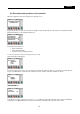
4.2. Hydraulic connections
Connect the PVC piping water inlets and outlets of the swimming pool to the heat pump inlet and outlet. The
connection will be performed through a by-pass over the filtering circuit of the swimming pool after the filter and
before the water treatment. .
Set the by-pass until the pressure switch be between 200 PSI – 300 PSI.
Always follow the installation diagram showed above. Chemical doser must be installed 25 cm under the heating
pump. If not possible contact the installer.
The unit is provided with three PVC unions.
Always respect the hydraulic connection diameters specified for each machine.
A full-flow shut-off valve should be installed on each of the hydraulic elements in the equipment, so that each of
these may be isolated if needed (for repairs, substitutions, etc.) without the need to drain the circuit.
Anti-vibration dampers should be installed in the inlet and outlet of the machine, in order to avoid vibrations which
may cause cracks or breakage in the hydraulic connections.
In order to avoid possible breakage, do not force the PVC tubes connected to the water supply.