Portable signal generator programming software SP-8848 Instruction Manual Ver.2.
Portable signal generator programming software SP-8848 Instruction Manual 2007.2 Ver.2.
CONT E NT S Chapter 1 About the SP-8848 ......................................................................................................................................... 1 1.1. General .................................................................................................................................................................... 1 1.2. Features...........................................................................................................................................
2.9.2. Window screen and description ...................................................................................................................... 67 2.9.3. Operation methods ......................................................................................................................................... 68 2.10. Creating and editing the optional patterns............................................................................................................ 69 2.10.1. Startup method.....
2.18. ClosedCaption/V-chip data transmission tool ..................................................................................................... 105 2.18.1.Startup method............................................................................................................................................. 105 2.18.2. Window screen displays and descriptions .................................................................................................. 105 2.18.3. Operation method .............
Forew Word Thank you for purchasing the programmable video signal generator. This manual provides details on how to use the SP-8848 software program to edit, create, send and receive data used for the programmable video signal generator (hereafter abbreviated to "VG"). (The figures and diagrams referred to in this manual show what applies when the VG-848 has been connected, and there may be differences when connections are made with another VG. Refer to the help provided for each editing program.
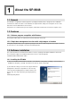
1 About the SP-8848 1.1. General The SP-8848 is an application software program for operating the VG-848, and it is designed to run in a Windows environment. It enables the statuses of the VG-848 to be captured and its settings to be changed. It can also create data and execute the data which has been created. All operations are conducted at the personal computer, and the data created can be stored in the computer as files. 1.2. Features 1.2.1.
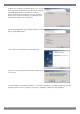
(3) On the "Select installation destination" dialog screen, select the directory into which the SP-8848 is to be copied. As the default, the "ASTRO¥SP-8848" directory is created in the C: drive root directory, and the files are copied into it. The copy destination directory can be changed to any directory specified by the user. Click the [Browse] button and set the directory. (4) Select the [Install] button. The file installation dialog screen now appears, and installation begins.
Chapter 1 About the SP-8848 1.3.2. Installing the USB driver (1) When the system is connected with the VG for the first time, it recognizes the VG, and the [Add New Hardware Wizard] dialog box appears. Select the [Next] button. (2) Select [Search for optimal driver for device in use (recommended)] as the search method, and select the [Next] button. (3) Place the SP-8848 installation CD in the CD drive, check [Specify search location], specify CD drive and select the [Next] button. (4) Check that "VgUsb.
1.3.4. Directories and files The directory and files listed below are created by the installation of the software. Specified directory (default: C:¥ASTRO¥SP-8848) Data (data files used by the data editing programs) (*.lot) Sample.lot AutoDispt (*.adp) Sample.adp Group (*.grp) Sample1.grp,Sample2.grp Image (*.vbm) usagi.vbm XGA.vbm SXGA.vbm UXGA.vbm 1080_10bit.vbm (*.bmp) usagi.bmp XGA.bmp SXGA.bmp UXGA.bmp OptPtn (*.mc) g1_test.mc/g8_test.mc/window.mc/ptn_test.mc/256_col.mc/CbarGray.mc/IMG1.m c/Crosst90.
Chapter 1 About the SP-8848 Exe (executable files of SP-8848) (*.exe) ADEdit.exe/CharEdit.exe/CnfgEdit.exe/GrpEdit.exe/LpEdit.exe/OptEdit.exe/PrgEdit. exe/ VbmCvt.exe/VGBase.exe/VGManage.exe/CDCEdit.exe/CurTool.exe/Monitor.exe/VersionUp.e xe/ (*.dll) CmdDll.dll/GuiCmd.dll/ADDll.dll/CharFile.dll/CVSBMP.dll/GrpSetDll.dll/Layout.dl l/LimitDll.dll/OptPtnFile.dll/PrgFiles.dll/RegDll.dll/TransDll.dll/TransUsb.dll/DDCE dit.dll/DDCFile.dll/CDCFile.dll/ImgCom3.dll/imged32.dll/ImgEtc3.dll/ImgFile3.dll/I mgTiff3.
1.3.6. Registration of Registry The data is registered in the registry as below. HKEY_LOCAL_MACHINE ¥Software¥Astrodesign¥SP8848¥ By starting up SP-8848, the data is copied from the above registry to the below registry. HKEY_CURRENT_USER ¥Software¥Astrodesign¥SP8848¥ When uninstalling it, the data after ¥SP8848 in “HKEY_LOCAL_MACHINE” is deleted, however, the data after ¥SP8848 in “HKEY_CURRENT_USER” is not deleted.
Chapter 1 About the SP-8848 The below screen is shown. (4) By pressing “Repair” button, SP-8848 is re-installed. (5) When repair work is done, SP-8848 can be used.
8
2 Operation 2.1. General The basic operations consist of starting up "VGBase," creating and editing data, sending the data to and receiving it from the VG, and storing the created data in the memory. The layout data used by "VGBase" is grouped together in sets, and the data, data numbers, codes, etc. sent to the VG are retained in the memory. (For details on how to create and edit the sets of data, refer to the help sections in the editing programs concerned.
(3) The "Layout Info Setting" (layout data setting) dialog box for setting the data at startup appears. If layout data is to be used, select [Use Layout File], and click the [OK] button. Otherwise, select [No Info], and click the [OK] button. If the no data layout will be used, "VGBase" is started up here. (4) When the layout data is going to be used, the "Load File" file selection dialog box appears. (It does not appear when the layout data is not going to be used.) Select the "Sample.
Chapter 2 Operation 2.3. Closing VGBase Procedure for closing "VGBase" Click the [Close] button. 2.4. Configuration settings Procedure for changing the VG execution mode and other configuration settings 2.4.1. Startup method Click the [Config] button of "VGBase." This starts up the "Configuration Editor" program which performs the configuration settings. 2.4.2. Window screen and description ■ Environment page The directory containing the data files can be set on this page.
Click [Apply] so that the configuration settings will take effect and the actual changes will be made. When this button is clicked on the [Interface] page, the commands are sent to the VG unit and the settings are changed only if communication is enabled. If communication is disabled, only the configuration data managed by the PC will be updated. Bear in mind that even when the settings have been changed, these changes will be lost if the software is closed without clicking the [Apply] button first.
Chapter 2 Operation When VG (Serial) has been selected as the communication method: Port [Sense] button Speed Data Size Parity Stop Bits The port number is selected here. This is used to detect the setting speed of the VG automatically. 9600, 19200, 38400, 57600 or 115200 is selected as the transfer rate setting here. This setting selects the communication data size (fixed at 8 bits). Even, Odd or None is selected as the parity setting here. 1, 1.5 or 2 bits are selected as the Stop Bits setting here.
*1: As a general rule, use the default value for the port number. If it cannot be used due to the network connected, change to a different port number for use. When the [Edit] button is pressed, a setting dialog box such as the one shown below appears. Name IP Address The VG name is displayed here. The IP address is displayed here.
Chapter 2 Operation ■ Control page The display mode settings of the VG can be changed on this page. Display "Direct Display" or "Group Display" can be selected here as the display mode. When the "Group Display" mode has been selected, the "Group" number must be specified.
2.5. Creating and editing the program data This section describes how the VG program data is set. Program data can be created, edited, sent to the VG, registered on the panel ROM or memory card, executed and received from the VG. 2.5.1. Startup method Click the [Program] button of "VGBase" to start up the "Program Editor." When the editor starts up, the timing data setting screen appears as the default display. 2.5.2.
Chapter 2 Operation Help Help details are displayed by pressing the button. Tool buttons Show Err: When the button is clicked, the error window is displayed. Check the values of the data which has been set. If a value outside the setting range has been input, which data contains the error is indicated on the error description display screen. Execute: When the button is clicked, the program data now being edited is executed without its being registered in the VG.
Basic operations ①Loading a file Before creating new data, proceed with "Creating and editing the program data" in (2) on the next page. 1) Press the [Load] button to open the "Load File" file selection dialog box. 2) Select the filename. 3) Select the type of the program data ([Timing], [Output], [Pattern] or [Action]) to be loaded, and press the [OK] button. Only the selected data is now loaded. The data which has not been selected is not updated.
Chapter 2 Operation ③Saving the file After changing the program data, click the [Save] button or [Save As] button to save the data in the file. When the [Save] button is clicked: The data is saved in the file and any existing data in that file is overwritten. When the [Save As] button is clicked: 1) The "Save File" file selection dialog box appears. 2) Input the filename, and select the [OK] button. The displayed data is now saved in the new file. ④Sending the program data 1) Select the [Send] button.
■ Timing data setting screen Horizontal timing data setting Vertical timing data setting screen [Setting the data] ● Align the mouse cursor with the data to be changed, and click the mouse. The data can now be keyed in. [Setting the input mode] ● Select microseconds (usec), dots or kHz as the units for the horizontal timing (H TIMING) data and milliseconds (msec), H or Hz as the units for the vertical timing (V TIMING) data. The check box enabling the unit to be input changes.
Chapter 2 Operation Timing data settings [Frequencies] Dot clock frequency Horizontal sync frequency Vertical sync frequency 5.000 to 300.000 MHz 10.000 to 300.000 kHz 15.600 to 200.000 Hz [Horizontal timing data] H Period H Disp H Sync H Backp H Frontp HD start HD width H Blanking 0.000 to 99.999µsec 0.000 to 99.999µsec 0.000 to 99.999µsec 128 to 8192 dot 48 to 4096 dot 0 to 4096 dot 1-dot increments 1-dot increments 1-dot increments 0.000 to 99.999µsec 0 to 4096 dot 1-dot increments 0.
■ Output condition data setting screen Output condition data setting screen [Setting the data] ● Select the applicable radio buttons. ● Where an edit box is provided, align the mouse cursor with the data to be changed, and click the mouse. The data can now be keyed in.
Chapter 2 Operation Output condition data settings Mode ANALOG, Tri-Sync (1080) ,Tri-Sync (720) ,NTSC ,PAL ,SECAM is selected here. HS "NEGA," "POSI" or "OFF" is selected here as the HS polarity setting. VS "NEGA," "POSI" or "OFF" is selected here as the VS polarity setting. CV "OFF," "R," "G," "RG," "B," "RB," "GB" or "RGB" is selected here as the CV setting. CS "NEGA," "POSI" or "OFF" is selected here as the CS polarity setting. VIDEO LEVEL A voltage level from 0.3 to 1.
■ Pattern data setting screen Buttons for selecting the patterns Character pattern settings Buttons for setting the respective patterns Selecting the patterns Select the pattern to be displayed while the VG is running. Select "Multi Pattern" or "Single Pattern" as the Mode setting. ("Multi Pattern" is the default.) NAME, R, G, B and INV can be set at the same time for any of the patterns. ● When "Multi Pattern" is selected : The OPT1 and OPT2 patterns cannot be set at the same time.
Chapter 2 Operation Pattern selection CHARA Character CROSS Crosshatch DOTS Dots CIRCLE Circle Center marker Edge marker Diagonal line CURSOR Cursor NAME Program data name COLOR Color bar GRAY Gray scale BURST Burst WINDOW Window OPTI1 Optional pattern 1 OPT2 Optional pattern 2 R Red output G Green output B Blue output INV Inversion Pattern settings CHARA: Character pattern This button is used to set the character pattern. Code The character code is set here.
CROSS: Crosshatch pattern This button is used to set the crosshatch pattern. The crosshatch pattern is always displayed after the screen center has been calculated. The screen center can be calculated when the number of display dots and number of display lines are odd numbers. However, when they are even numbers, the actual screen center will be one dot to the right and one line below the center. An error results when 0 is set for both H and V.
Chapter 2 Operation DOTS: Dot pattern This button is used to set the dot pattern. The dot pattern is always displayed after the screen center has been calculated. The screen center can be calculated when the number of display dots and number of display lines are odd numbers. However, when they are even numbers, the actual screen center will be one dot to the right and one line below the center. An error results when 0 is set for both H and V.
CIRCLE: Circle pattern This button is used to set the circle pattern. The number of circles, etc. can be set. Format This is selected on the basis of the data which has been set. Aspect The aspect ratio of the monitor is set here. The ratio is considered to be 1:1 when 0 is used for H or V setting.
Chapter 2 Operation CURSOR: Cursor pattern This button is used to set the cursor pattern. Format The shape of the cursor is selected here. Flicker The flicker setting is selected here. Position (PosDisp) The method of displaying the cursor position is selected here. Step The cursor movement step is selected here. Color The RGB values of the cursor are selected here. Background Color The RGB values of the background color are selected here.
COLOR: Color bar pattern This button is used to set the color bar pattern. The color bar pattern is always drawn in accordance with the interval provided and from the top left corner toward the screen center. This interval setting is used for both color bar and gray scale. Mode Interval Direction Chapter 5 Repeat Color 30 The interval setting increment (specified as a percentage or dot number) is selected here. The horizontal (H) width and vertical (V) width are selected here.
Chapter 2 Operation GRAY: Gray scale pattern This button is used to set the gray scale pattern. When the analog mode or Tri-Sync has been selected as the output condition "Mode" setting, "Level" can be set; when the TTL mode has been selected, "Color" can be set. The gray scale pattern is always drawn in accordance with the interval provided and from the top left corner toward the screen center. Mode The interval setting increment is selected here. Direction The layout direction is selected here.
BURST: Burst pattern This button is used to set the burst pattern. Format The drawing start point is selected here. Step The increment for the thickness of the vertical lines is selected here. Interval The number of vertical lines of the same thickness which are to be displayed is selected here.
Chapter 2 Operation WINDOW: Window pattern This button is used to select the window pattern. When the analog mode or Tri-Sync has been selected as the output condition "Mode" setting, "Analog Color" can be set; when the TTL mode has been selected, "TTL Color" can be set. Mode The size setting increment (specified as a percentage or dot number) is selected here. Size The horizontal size (H) and vertical size (V) are selected here. Format The window already set is selected here.
WINDOW: Window 4Level Flicker Set the value of Window 4 Level Flicker. Window level can be set 4-level. Each level can output in the setting time (V unit). Time The flicker time is set. 0 to 255 v Level The flicker level is set. 0 to 255 Close The Window 4Level Flicker setting screen is ended, and it returns to the Window setting screen. * 8bit or 10bit can be selected in VG-835. The level can be set between 0 to 255 in 8 bit mode, 0 to 1023 in 10 bit mode.
Chapter 2 Operation WINDOW: Window 16Level Flicker Set the value of Window 16Level Flicker. Window level can be set 16-level. Each level can output in the setting time (V unit). Time The flicker time is set. 0 to 255 v Level The flicker level is set. 0 to 255 Close The Window 16Level Flicker setting screen is ended, and it returns to the Window setting screen. * 8bit or 10bit can be selected in VG-835. The level can be set between 0 to 255 in 8 bit mode, 0 to 1023 in 10 bit mode.
OPT: Optional pattern This is used to set the optional patterns. When an optional pattern is set, no other patterns can be superimposed onto it. 36 Option 1 (OPT1) The hexadecimal code of the optional pattern is set here. Option 2 (OPT2) The hexadecimal code of the optional pattern is set here.
Chapter 2 Operation NAME: Program data name This is used to display the name of the program data displayed. A new program data name can be set by inputting the name into "Program Name" of the program data name setting tab on the pattern data setting screen and saving it or sending it to the VG. The same procedure is adopted for changing a name.
GRAPHIC: Graphic color This is used to set the graphic colors. When the analog mode or Tri-Sync has been selected as the output condition "Mode" setting, "Analog Color" can be set; when the TTL mode has been selected, "TTL Color" can be set. When the analog mode or Tri-Sync has been selected as the output condition "Mode" setting: Analog color : The RGB values are set here. When the TTL mode has been selected as the output condition "Mode" setting: TTL Color : The TTL color values are set here.
Chapter 2 Operation ■ Action data setting screen Pull-down scroll Action data setting screen Action data setting screen Click the check box to the left of the action data type to be set to check it. The setting items for each type can now be selected. Pull-down scroll Scrolling can be simulated by employing the 2-3 pull-down function and other scroll functions.
Pattern pull-down scroll setting screen Interval2 The interval from 0 to 999V is set here. Interval3 The interval from 0 to 999V is set here. Interval4 The interval from 0 to 999V is set here. Pattern H‐Step2 The number of steps from 0 to 4095 dots is set here. H‐Step3 The number of steps from 0 to 4095 dots is set here. H‐Step4 The number of steps from 0 to 4095 dots is set here. V‐Step2 The number of steps from 0 to 4095 dots is set here.
Chapter 2 Operation Setting ranges Action interval Action Interval 1 to 999 V Interval2 0 to 999 V Interval3 0 to 999 V Interval4 0 to 999 V Character flicker ON/OFF Window flicker ON/OFF Pattern scroll Character Scroll Left, Right, Up, Down, LeftUp, RightUp, RightDown, Moving Graphic Scroll Left, Right, Up, Down, LeftUp, RightUp, RightDown, Moving H Repeat 1 to 15 V Repeat 1 to 15 H Step 1 to 4096 dots V Step 1 to 4096 dots H Step2 0 to 4096 dot V Step2 0 to 4096 dot H Step3
■ Audio data setting screen Sweep Mode settings Frequency settings Level settings Sweep Mode "Sweep OFF," "Frequency," "LEVEL(L)" or "LEVEL(R)" is selected as the Sweep Mode setting. Frequency The frequency is set in the LEFT and RIGHT fields. Any frequency from 100 to 20,000 Hz can be set in each field. The settings are performed in 100 Hz increments. Level The level is set in the LEFT and RIGHT fields. Any level from 0 to 2000 mV can be set in each field.
Chapter 2 Operation ■ HDMI data setting screen ※A setting screen is a thing at the time of VG-849 selection.
No. ① Item name HDMI Mode Video Details Set HDMI output mode. Select from OFF, HDMI, HDMI1.1, DVI, or AUTO. ・Video Fomat Select the video format. Select from RGB, Y444, Y422_16, Y422_20, or Y422_24. ・Video Level Set the format of the video level. Select from Full range, Limited range, or USER. ② If “USER” is selected, it is possible to input setting range by video format.
Chapter 2 Operation ■ InfoFrame data setting screen ※A setting screen is a thing at the time of VG-849 selection.
No. Item name ① AVI ② SPD ③ Audio 46 Details ON/OFF Select ON or OFF of InfoFrameAVI. Type Display the type of InfoFrameAVI. Version Set the version of InfoFrameAVI. Select either 1 or 2. ScanInfo Set the ScanInfo. Select from NoData, Overscanned, or Underscanned. BarInfo Set about the BarInfo. Select from NotValied, Vert, Horiz or Vert&Horiz. Scaling Set about the Scaling. Select from unknown, Vert, Horiz or Vert&Horiz. ActiveFormatInfo Set about the ActiveFormatInfo.
Chapter 2 Operation ④ MPEG LevelShift Set the level shift. Set between 0 and 15. Down-mixInhibit Select “Permitted” or “Prohibited” of using DownMix. ON/OFF Select ON or OFF of InfoFrameMPEG. Type Display the Type of InfoFrameMPEG. Version Set the version of InfoFrameMPEG. One version is fixed. BitRate Set the BitRate within the range of 0 to 4294967295. (4294M967K295Hz) Frame Set about the Frame. Select from unknown, I Picture, B Picture or P Picture. FieldRepeat Set about FieldRepeat.
■ ACP data setting screen ※A setting screen is a thing at the time of VG-849 selection. ① ② ③ No. ① 48 Item name ACP Packet Details ON/OFF Select ON or OFF of ACP. ACP Type ACP type setup. Please make a selection from Generic Audio, IEC60958, DVD Audio, or Reserved for SACD. DVD-Audio Type Dependent Generation DVD-Audio Type Dependent Generation setup. Only one way to choose. Copy Permission Copy Permission setup. Please make a selection from 0, 1, 2, or 3.
Chapter 2 Operation ② ISRC 1 ③ ISRC 2 Count_U setup. Please make a selection from 0 to 255. Q_A Q_A setup. Please make a selection from 0 or 1. Q_S Q_S setup. Please make a selection from 0 or 1. Q_U Q_U setup. Please make a selection from 0 or 1. Move_A Move_A setup. Please make a selection from 0 or 1. Move_S Move_S setup. Please make a selection from 0 or 1. Move_U Move_U setup. Please make a selection from 0 or 1. ON/OFF Select ON or OFF of ISRC1. ISRC Cont ISRC Cont setup.
■ CEC data setting screen ※A setting screen is a thing at the time of VG-849 selection. ① ② ③ ④ No. Item name ① CEC Mode setting ② VG Logical Address ③ Transmission command is set ④ Receiving command is set. 50 Details Set CEC Mode. Select among “Monitor”, “Sending” and “Respond”. VG Logical Address From which device the command is transmitted is set. Set the value from 0 to F. * VG Logical Address and TX Initiator are adjusted each other.
Chapter 2 Operation ■ ADF data setting screen ※A setting screen is a thing at the time of VG-849 selection. The "EIA/CEA-861B standard" aspect ratio evaluation pattern can be set as optional pattern 1F. The detailed settings of optional pattern 1F are shown below. Aspect Mode For setting the actual aspect ratio. AFD Aspect For setting CodeFrame of the AFD which is defined by the EIA/CEA-861B standard. AFD Type For setting the number of the AFD which is defined by the EIA/CEA-861B standard.
■ ClosedCaption/V-chip data setting screen ClosedCaption V-chip V-chip V-chip data is set up. Please refer to a "2.18. ClosedCaption/V-chip data transmission tool" for details. ClosedCaption Caption data is set up. Please refer to a "2.18. ClosedCaption/V-chip data transmission tool" for details.
Chapter 2 Operation ■ Teletext data setting screen Execute Line Page Execute Select ON or OFF for the output Line Set the teletext data transmission mode. ・4line : Four lines are set as the mode for transmitting the teletext data. Display lines : Field1 = 20, 21. Filed2 = 333, 334 ・8line : Eight lines are set as the mode for transmitting the teletext data. Display lines : Field1 = 13, 14, 20, 21.
Page This is used to set the pages for each of the channels. The contents of a page are as being shown below. If a page with any other number is set, only the page number will be displayed.
Chapter 2 Operation ■ Macrovision data setting screen Macrovision Mode Mode The output mode of a Macrovision is set up. The modes which can be set up for every setting timing differ.
The mode which can be set up for every timing. Timing NTSC-M NTSC-J NTSC-443 PAL-60 PAL-M PAL PAL-N PAL-Nc SECAM 56 Mode OFF DVD/STB Type 1 DVD/STB Type 2 DVD/STB Type 3 VHS USA VHS US obs.
Chapter 2 Operation ■ IA-575 data setting screen ScartOutput setting Timing setting Pattern setting ScartOutput The IA-575 can switch its output signals to VBS output, Y/C output or RGB output signals. Timing When a timing system other than one supported by the IA-575 has been selected, it is possible to specify the timing system which are to be output from the IA-575.
2.6. Creating and editing the user characters This section describes how the VG's user characters (hereafter referred to as the "characters") are set. The VG characters can be created and edited, edited characters can be sent to the VG and registered on the panel ROM or memory card, and characters from the VG can be received. 2.6.1. Startup method Click the [Char] button of "VGBase" to start up the "Character Editor." 2.6.2. Window screen and description ⑥ ① ⑤ ② ③ ⑦ ④ No.
Chapter 2 Operation 2.6.3. Operation methods (1)Loading the file Before creating new characters, proceed with "Creating and editing the character data" in 2) below. 1) Press the [Load] button to open the "Load File" file selection dialog box. 2) Select the file. When [Display Image] is checked, the selected file is previewed. 3) Click the [OK] button. The character of the selected file is now displayed in the editing area.
(5)Sending the characters 1) Click the [Send] button. The "Send to VG" code selection dialog box appears. 2) Set the character code (0xE0 to OxEF in hexadecimal format). 3) Click the [OK] button. The character is now sent to the VG and registered. (The code shown at [Code] now changes to that of the sent character.) (6)Receiving the characters 1) Click the [Receive] button. The "Receive from VG" code selection dialog box appears. 2) Set the character code (0xE0 to OxEF in hexadecimal format).
Chapter 2 Operation 2.7. Creating and editing the group data This section describes how the VG's group data is set. The VG group data can be created and edited, edited group data can be sent to the VG and registered on the panel ROM or memory card, and group data from the VG can be received. Different program display screens are displayed depending on the VG model which is connected. 2.7.1. Startup method Click the [Group] button of "VGBase" to start up the "Group Editor." 2.7.2.
No. Item name Details ① No The number of the group data registered in the VG appears here. ② Neme The name of the group data registered in the VG appears here. ③ Edit When this button is clicked, the "Program Layout Editor" program data registration dialog box appears. ④ Group The loaded program data is displayed here. ⑤ Cell editing buttons ● ↑, ↓: The [up] button and [down] button enable the group data to be scrolled up and down.
Chapter 2 Operation (3)Saving the file The displayed data is saved in the file. Click the [Save] button. → The data is saved in the selected file and any existing data in that file is overwritten. Click the [Save As] button. → The data is saved in a new file. (*) The group data name can be set by inputting it into [Name] of the "Group Editor." This name is stored in the file when a panel ROM is used but it will not be sent to the VG. (4)Sending the group data 1) Click the [Send] button.
2.8. Creating and editing the auto display data This section describes how the VG's auto display data is set. The VG auto display data can be created and edited, edited auto display data can be sent to the VG and registered on the panel ROM or memory card, and auto display data from the VG can be received. 2.8.1. Startup method Click the [Auto Disp] button of "VGBase" to start up the "Auto Display Editor." 2.8.2. Window screen and description ① ⑤ ② ⑦ ⑥ ③ ④ No.
Chapter 2 Operation 2.8.3. Operation methods (1)Loading the file Before creating new auto display data, proceed with "Creating and editing the auto display data" in (2) below. The auto display data is loaded from a file in which it was saved. 1) Click the [Load] button. The "Load File" file selection dialog box now appears. 2) Select the file, and click the [OK] button. The auto display data of the selected file is now displayed on the [Auto Display] auto display data list.
(6)Printing the auto display data 1) Click the [Print] button. 2) The "Print" dialog box appears. Set the margins here. 3) Click the [OK] button. The displayed data is now printed. 4) To change the printer which has been set, click the [Set Printer...] button. 5) The printer setting dialog box appears. Proceed with the printer settings. For details on how the items on this dialog box are set, refer to the instruction manual for Windows or for the printer which will be used.
Chapter 2 Operation 2.9. Converting the image data This section describes how the VG's image data is set. BMP data or JPG data can be converted into VBM data for use by the VG, VBM data can be sent to the VG and registered on the memory card, VBM data from the VG can be received, and this data can be saved as VBM files. 2.9.1. Startup method Click the [Image] button of "VGBase" to start up the "Image Converter." 2.9.2. Window screen and description ① ② ③ ④ ⑤ ⑥ No.
2.9.3. Operation methods (1)Loading the image file BMP files, JPG files and VBM files are loaded and displayed. 1) Click the [Load] button. 2) The "Load Image File" file selection dialog box is opened. Select the file type (BMP, JPG or VBM data), and select the file. If [Display Image] is checked, the selected file is previewed. 3) Click the [OK] button to load the selected image file.
Chapter 2 Operation 2.10. Creating and editing the optional patterns This section describes how the VG user-created optional patterns (hereafter abbreviated to "optional patterns") are set. The VG optional patterns can be created and edited, edited optional pattern source codes can be compiled, optional pattern data can be sent to the VG and registered on the memory card, and optional patterns from the VG can be received. 2.10.1.
No. Item name Details ① Code The code registered in the layout data appears here. ② Name The name of the displayed optional pattern appears here. ③ Editing screen The source codes of the optional patterns are created, changed and displayed on this screen. ④ Compiling screen Messages appear here during the compiling process.
Chapter 2 Operation ・Simulation screen ① ② ③ ④ ⑤ No. Item Description ① Plane switching Simulated pattern can be displayed by each plane, such as 8-bit, Window, ② Output screen Simulated pattern is displayed. ③ Compile screen Message for compiling is displayed. ④ VBM data-izing button 1-bit and Mix. The pattern that is displayed in the output screen is made to be a file of 256-color VBM data ⑤ Close Close the Simulation screen.
2.10.3. Operation methods (1)Loading the file Before creating new optional pattern data, proceed with "Creating and editing the optional patterns" in (2) below. The source code is loaded from a file which has already been saved. 1) Click the [Load] button. 2) The "Load File" file selection dialog box is opened. Select the file, and click the [OK] button. 3) The source code of the selected file is now displayed in the editing area.
Chapter 2 Operation (6)Printing the optional patterns 1) Click the [Print] button. 2) The "Print" printer setting dialog box appears. Set the margins here. 3) Click the [OK] button. The displayed optional pattern source code is now printed. 4) To change the printer environment which has been set, click the [Set Printer...] button. 5) The printer setting dialog box appears. Proceed with the printer settings.
2.10.4. Convert to 256-color VBM file User option pattern is converted to 256-color VBM file. (1)Write a source code in the edit area. Click [Compile] button, then confirm the message “Compile OK” on the Compile screen is displayed and compile is completed. By doing this, option pattern language that is a “middle language” is made from source code. (2)Click[Exec]button. Display the screen of compiled Option pattern data on the Simulation window “Execute Image”. If compile fails, black screen is displayed.
Chapter 2 Operation ■ Caution when making 256-color VBM file The display color of VBM file is 256-color only. When displaying 8-bit plane (256-color), 1-bit plane (one color) and Window plane (one color) simultaneously, the display color is supposed to be 258-color. In this case, upper two-color of 8-bit plane is assigned to 1-bit plane and Window plane. (1) 8-bit, 1-bit and Window plane are displayed simultaneously. Palette No. 0 1 2 3 . . .
2.11. Monitoring and changing the IP/Gateway address This section describes how to monitor the statuses of the VGs which have been connected using a LAN communication setup. It also explains how to change the IP addresses of the connected VGs. 2.11.1. Startup method Click the [Monitor] button of "VGBase" to start up the "Monitor." 2.11.2. Window screen and description Monitoring screen IP Change Monitoring screen The statuses of the connected VGs are displayed here.
Chapter 2 Operation 2.11.3. Operation methods (1)Monitoring The statuses of the connected VGs can be monitored by observing the icon displays at the far left of the screen and checking what appear in the [State] column. There are three VG statuses: "Normal" (indicating that the VG is functioning normally), "VG Error." (indicating that trouble has occurred in the VG) and "Network Error." (indicating that trouble has occurred in the network). (2)Changing an IP address 1) Click the [IP Change] button.
2.12. Selecting and editing the layout data files This section explains how to select and edit the layout data files used by "VGBase." 2.12.1. Startup method (1)Layout Info Setting Click the [Select] button of "VGBase" to start up the "Layout Info Setting." Select "No Info" when no layout data files are going to be used and [Use Layout File] when they are going to be used. When [No Info] is selected, operation returns to "VGBase" straight away. In this case, the layout data cannot be edited.
Chapter 2 Operation 2.12.2. Window screen and description (Layout Edit) ■ Program tab ① ③ ⑤ ④ ② No. Item Details ① Layout Name The name of the layout data is displayed here. ② Layout data list The program data which has been registered is displayed here. ③ Data folder The folder of the registered program data is selected. The folder that can be selected by set VG is different. ④ Data file list The data created by the editing program is displayed here.
About the data folder The folder of the registered program data is selected. The folder that can be selected by set VG is different. VG VG-848 VG-849 VG-858 VG-859 VG-830 VG-835 VG-835-A VG-857 Other VG folder Program Program Program Program Program Program Program Program Program VGInt VGInt VGInt VGInt VGInt VGInt VGInt VGInt VGInt2_848 VGInt2_849 VGInt2_848 VGInt2_849 VGInt2_848 VGInt2_835 VGInt2_835 VGInt2_835 VGInt3_849 VGInt3_849 ■ Character ① ④ ③ ② 80 No.
Chapter 2 Operation ■ Group tab ① ④ ③ ② No. Item Details ① Layout Name * See same item in program tab section. ② Layout data list * See same item in program tab section. ③ Data file list * See same item in program tab section. ④ Set * See same item in program tab section.
■ AutoDisplay tab ① ④ ② ③ 82 No. Item Details ① Layout Name * See same item in program tab section. ② Layout data list * See same item in program tab section. ③ Data file list * See same item in program tab section. ④ Set * See same item in program tab section.
Chapter 2 Operation ■ Image tab ① ④ ③ ② No. Item Details ① Layout Name * See same item in program tab section. ② Layout data list * See same item in program tab section. ③ Data file list * See same item in program tab section. ④ Set * See same item in program tab section.
■ Opt-Ptn tab ① ④ ③ ② 84 No. Item Details ① Layout Name * See same item in program tab section. ② Layout data list * See same item in program tab section. ③ Data file list * See same item in program tab section. ④ Set * See same item in program tab section.
Chapter 2 Operation 2.12.3. Operation methods (Layout Edit) ■ Editing the layout data 1) Click the tab ([AutoDisplay], [Image], [Opt-Ptn], [Program], [Character] or [Group]) corresponding to the type of data which is to be registered as the layout data. The [Selectable File List] of the data file which corresponds to the selected tab is displayed. 2) Select the data to be registered from the [Selectable File List].
■ Receiving the data 1) Click the [Receive] button. The "Transfer Data" data selection dialog box appears. 2) Select the data to be received. Before receiving it, check the data. (It takes time for all the data to be received. To test receiving the data quickly, check [Character Data] or [Auto Display Data], and receive it.) 3) Click the [OK] button. 4) The progress display starts, and the selected data is received from the VG.
Chapter 2 Operation 2.13. Setting the port number and IP address This section describes how to set the port number and IP address for the individual VGs which are connected serially. 2.13.1. Startup method Select [Start] → [Programs] → [SP-8848] → [IPAddressSet]. 2.13.2. Window screen and description ① ③ ② ④ No. Item Details ① Port No. The number of the VG's port is set here. ② Serial settings ● Com port: The port number is selected here. ● Speed: The transfer (baud) rate is set here.
2.13.3. Operation methods ■ Setting the port number and IP addresses 1) Select the serial settings in each of the text boxes under [Serial Setting]. 2) Input the port number which is to be set in the [Port No] text box. Set the same port number for all the VGs connected by LAN communication. 3) Input the IP address to be set in the [IP Address] text box. Set a different IP address for each VG. 4) Press the [Send] button. The port number and IP addresses are sent to the VGs. 2.13.4.
Chapter 2 Operation 2.14. Color difference coefficient data editing program This section describes how to use the editing program to set the color difference coefficient data of the VG. The program enables the color difference coefficient data of the VG to be edited in Windows, the edited color difference coefficient data to be sent to the VG, and color difference coefficient data from the VG to be received. 2.14.1. Startup method Select [Start] → [Programs] → [SP-8848] → [CDCEdit]. 2.14.2.
2.14.3. Operation methods (1)Loading the file The color difference coefficient data is loaded from a file in which it was saved. 1) Click [Open] on the [File] menu. The file selection dialog box now appears. 2) Select the file, and press the [OK] button. 3) The data of the selected file is now displayed. (2)Creating and editing the color difference coefficient data The color difference coefficient data is edited. 1) Input the data in a range from 0.0000 to 1.0000. 2) Input the name of the data in "Name.
Chapter 2 Operation 2.14.4. Menus ■ [File] menu Load This is used to load data from the files. Save This is used to save data in the files. Save As This is used to save the data under a different filename. Print This is used to print the displayed data. Close This is used to close the program. ■ [VG] menu Send to VG This is used to send the color difference coefficient data being edited to the VG. Receive from VG This is used to receive the color difference coefficient data from the VG.
2.15. Creating and editing the DDC data This section describes the program used to set DDC data of the programmable video signal generator (hereafter abbreviated to "VG"). The program enables the DDC data of a DDC-compatible monitor to be send, received and edited in Windows. 2.15.1. Startup method Select [Start] → [Programs] → [SP-8848] → [DDCEdit]. 2.15.2.
Chapter 2 Operation No. Item ① DispMode selectors Details These are used to select either the GUI display mode or the binary display mode. ● GUI display mode For the block types supported by this mode, the data is displayed on a screen that allows for easy graphical readout. For block types which are not supported, the data is displayed in the binary mode. ● Binary display mode The data is displayed in a 128-byte binary format. ② Toolbar ● Open: Click this to open the DDC data.
2.15.3. peration methods ■ Creating new DDC data 1) Click [New] on the [File] menu. The dialog box for selecting the number of blocks (size of the monitor ROM) to be created appears. 2) Select a number of blocks which are to be created to fit in with the size of the monitor ROM, and press the [OK] button. The specified number of blocks are now created. The initial value of all the data is "0." (*) The number of blocks can be changed even after new blocks have been created.
Chapter 2 Operation ■ Sending data to the monitor The DDC data is saved in the monitor ROM. 1) When [Send] on the [VG] menu is selected or the button is clicked on the toolbar, the send dialog box appears. 2) Select DDC1 or DDC2B, and decide on the numbers of the blocks (how many blocks starting from block #0) to be sent. When the [Fix Monitor] button is pressed, communication with the monitor is initiated, and the amount of the data can be matched with the maximum size of the monitor ROM.
2.15.4. Menus ■ [File] menu Menu command Description of function New This is used to create new data. Open This is used to open a file. Load One-Block This is used to load the data of one block from a file. Save This is used to save data in the files. Save As This is used to save the data under a different filename. Close This is used to close the file. Properties This is used to display the file properties. Print This is used to print the displayed data.
Chapter 2 Operation ■ [Help] menu Menu command Description of function Contents This displays the help information. Index This displays a list of the help topics which can be searched. About This displays the version information. 2.15.5. Block operations ■ Inserting a block before the current block Click the block immediately below the position where the block is to be inserted. Click [Insert-up Block] on the [Edit] menu.
2.16. Cursor tool program This section describes how to move the VG's cursor pattern just as would be done using a mouse and save the coordinates of defective pixels and other data in files. 2.16.1. Startup method Select [Start] → [Programs] → [SP-8848] → [Curtool]. 2.16.2.
Chapter 2 Operation No. Item Details ① Toolbar ● New: Click this to create a new defective pixel list. ● Save: Click this to save the defective pixel list in a file and overwrite any existing data in that file in the process. ● Save As: Click this to save the defective pixel list in a new file. ● Pixel: Click this to add missing pixels to the defective pixel list. ● Line: Click this to add missing lines to the defective pixel list.
2.16.3. Operation method ■ Startup At startup, the VG model and currently executed resolution are captured, and a screen matching these states is displayed. In addition, the cursor pattern position changes to the center coordinates and the properties change to the default values. 1) Connect the VG and monitor, and display the VG's output screen on the monitor. 2) Connect the PC and VG, and turn on the power of the VG.
Chapter 2 Operation ■ Saving a defective pixel list in a file The displayed defective pixel list is saved in a file. The list is saved in the comma-delimited CSV format (with the .CSV extension). When [Save] on the [File] menu is selected: The data is saved in the selected file and any existing data in that file is overwritten. When [Save As] on the [File] menu is selected: 1) The file selection dialog box appears. 2) Input the filename, and press the [OK] button.
2.17. All data copy tool All data of VG can be copied to the same model VG that are connected through LAN communication at once. 2.17.1. Startup method Select the [Distributor] in [SP-8848] in [Program] of [start] 2.17.2. WINDOW SCREENS AND DESCRIPTION ① ⑤ ② ⑥ ③ ④ No. Item Details ① Data selection Select transmitting data ② Data reception This function is to receive the data from VG that has original data. Press the “Receive” button and IP address(VG) which has been already set is displayed.
Chapter 2 Operation 2.17.3. OPERATION (1) Before startup 1) Set LAN communication and IP address (VG) in the screen of [Config] in [VG Base]. 2) Use the same VG model, and the same IP address. 3) If the copied VG and copy to VG is not the same model, the data cannot be transferred. 4) The IP address which is set in No.1 in [Config] of [Base] are reflected. (2) Startup 1) Connect LAN communication of copied VG and copy to VG. 2) Connect PC to the copied VG and turn on each VG power.
e.g.) Suppose the data is set as below in [VGBase] [Config] [Interface] [VG(LAN)]. No. VGName IP address Setting of IP address 1 VG1 192.168.16.54 Class C 2 VG2 192.168.16.55 Class C 3 VG3 192.255.255.255 Class A 4 VG4 172.16.255.255 Class B 5 VG5 192.168.16.60 Class C In this case, the IP address that is set in No. 1 is Class C, the data is transmitted only to VG1, VG2 and VG5 whose IP address is set as Class C.
Chapter 2 Operation 2.18. ClosedCaption/V-chip data transmission tool Described here are the steps taken to send the closed caption data and V-chip data to the VG generator or receive the data from the VG generator and also to save the data settings in files. * This tool can be used with VG-848,858,849,859,849C,859C. 2.18.1.Startup method Select [Start] - [Programs] - [SP-8848] - [CCVEdit]. 2.18.2.
Caption setting screen No. Item Details ① V-chip setting display This button is used to display the V-chip setting screen. ② CC mode settings These are used to select closed caption mode 1, 2, 3 or 4 or select text mode 1, 2, 3 or 4. When a text mode has been selected, the text setting screen is displayed. ③ CC style settings These are used to set the caption data style. Depending on the style setting, the number of caption data which can be set varies.
Chapter 2 Operation ■ FontStyle setting screen ① ② ⑦ ③ ⑥ ④ ⑤ FontStyle setting screen No. Item Details ① SET ② No ③ Foreground ④ Opaque ⑤ Underline ⑥ Italic ⑦ Flash This is pressed to set the FontStyle data which has been checked. These are the numbers of the rows in which the settings are to be reflected. Makes the checked Caption oreground. * Invisible on the application. When one of these boxes is checked, the background becomes opaque.
■ Binary editor ① ② ④ ③ Binary data setting screen No. Item Details ① SET button This is pressed to convert the edited binary data into the caption data. ② Length The number set here becomes the effective character numbers. For example, if 32 letters data is input, but the “5” is input in the “length” item, the effective character data is from 1 to 5. ③ Control data The control data is set in the pull-down menu.
Chapter 2 Operation ■ Text data setting screen ⑧ ② ⑨ ① ③ ④ ⑤ ⑦ ⑥ 109
Text setting screen No. Item Details ① V-chip setting display This button is used to display the V-chip setting screen. ② CC mode settings These are used to select closed caption mode 1, 2, 3 or 4 or text mode 1, 2, 3 or 4. When a text mode has been selected, the text setting screen is displayed. ③ Tool buttons Load: Press this to load the data from a file. Save: Press this to save the edited data in a file.
Chapter 2 Operation ■ V-chip setting screen ① ⑫ ⑪ ② ③ ⑤ ④ ⑥ ⑨ ⑦ ⑩ ⑧ 111
V-chip Setting screen No. Item Details ① CC setting display This is pressed to display the closed caption setting screen. ② Tool buttons ● Load: Press this to load the data from a file. ● Save: Press this to save the edited data in a file. ● Send: Press this to send the edited data to the VG generator, and register it in the generator. ● Receive: Press this to receive data from the VG generator. ③ Program No The number of the program which has been sent or received appears here.
Chapter 2 Operation 2.18.3. Operation method ■ ClosedCaption (a) Closed captions Start up the program. The closed caption setting screen is the first screen to appear after startup. (b) Select the closed caption mode style. The number of rows of data which can be edited differs depending on the selected style. (c) Enter a check mark in the ROW check box corresponding to the row to be edited. Data can now be written into the editor area which has been checked. (d) Write the data in the editor area.
114
3 10bit Image data 3.1. 10bit Image data 10bit image data of the yacht barber who shows in the figure below is appended to SP-8848. The resolution becomes 1920x1080. Caution A copyright of yacht harbor of an upper figure belongs to "corporate judicial person Institute of Image Information and Television Engineers".
116
4 Error message reference Error message Code Panel ROM Unsetted 00 Prog No Disabled 01 Description of error (HEX) The EE-PROM has not been inserted into the panel ROM socket or the memory card has not been installed. The number of the program which was input turns out to have been set to "Disable" when direct display or a program is executed. DotClk over 02 DotClock in the horizontal timing data is outside the specified range.
OPT PTN FAT error 2C Error in user-generated optional pattern FAT. OPT PTN Not Registed 2D No user-generated optional patterns have been registered. BMP data No error 2E Error in the image data number. BMP data FAT error 2F Error in image data FAT. BMP data Not Registed 30 The image data has not been registered. Cur-DEV Incorrect 31 Illegal current data device (memory card or EEPROM). Key Not Available 32 The function cannot be used because the key lock function is activated.
SP-8848 NOTICE ● An incorrectly collated manual or a manual with missing pages will be replaced. ● All copyrights pertaining to this product are the property of ASTRODESIGN. ● This manual may not be copied in whole or in part without written permission. ● The contents of this manual are subject to change without prior notice due to improvements. ● The manufacturer will not be liable for any effects caused by incorrect operation.