TM AstroJet M1 COLOR PAGE PRINTER OPERATOR MANUAL ASTRO MACHINE CORP. 630 Lively Blvd. Elk Grove Village, IL 60007 Phone: (847) 364-6363 Fax: (847) 364-9898 www.astromachine.
SAFETY PRECAUTIONS THIS EQUIPMENT PRESENTS NO PROBLEM WHEN USED PROPERLY. HOWEVER, CERTAIN SAFETY RULES SHOULD BE OBSERVED WHEN OPERATING THE ASTROJET M1 PRINTER. BEFORE USING THE PRINTER, YOU SHOULD READ THIS MANUAL CAREFULLY AND FOLLOW THE RECOMMENDED PROCEDURES, SAFETY WARNINGS, AND INSTRUCTIONS: Keep hands, hair, and clothing clear of rollers and other moving parts. Avoid touching moving parts or materials while the machine is in use.
TABLE OF CONTENTS SECTION 1 – Getting Acquainted Front View Rear View Print Engine View Ink Tank Door View Control Panel Button/LED Indicators SECTION 2 – Installing the Printer Contents of Packaging Choose a Location Unpacking and Setup Hydrating the Printhead Cartridge Remove Service Station Transport Tab and Shipping Tape Assembling the Printer Connecting the Printer Connecting to the Computer Install the Printer Driver Install the Ink Tanks Install the Printhead Cartridge Removing the Head Media Guid
TABLE OF CONTENTS NOTES ______________________________________________________ ______________________________________________________ ______________________________________________________ ______________________________________________________ ______________________________________________________ ______________________________________________________ ______________________________________________________ ______________________________________________________ _______________________________________________
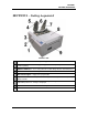
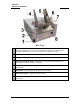
SECTION 1 GETTING ACQUAINTED SECTION 1 – Getting Acquainted Front View 1. Cancel LED Button – Cancels the job being printed. 2. Paper LED Button – Press to stop printing, press to restart printing. Press switch to continue printing. 3. 4. 5. ON/OFF LED Button – Use to turn power ON or OFF during idle time and maintenance. Rear Guide – Holds the media against the Front Plate. Rear Guide Support – Supports the paper/media. 6.
SECTION 1 GETTING ACQUAINTED Rear View 2 1. Main Power Switch, Receptacle and Fuse – Plug in power cord here. Switch turns main power ON/OFF. (Use Control Panel LED Power switch to turn off machine for cleaning and maintenance). Fuse protects the Printer’s electronic circuits. 2. USB Port Connection – The USB cable attaches to the Printer here. 3. Network Connection – The network cable plugs in here. 4. Envelope/Paper Media Guide – All printing is registered against this Guide.
SECTION 1 GETTING ACQUAINTED Print Engine View 1. Printhead Latch – When closed, connects the Ink Revolver Couplings with the Printhead Cartridge. When opened, retracts the Ink Couplings from the Printhead Cartridge and provides access to the Printhead Cartridge for cleaning and replacement. WARNING! Never attempt to open the Printhead Latch manually, severe damage will result.
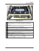
SECTION 1 GETTING ACQUAINTED Ink Tank Door View Ink Tank Securing Latches – Used to hold the Ink Tanks in the slots. 1. 4 NOTE: Please be sure that both sides at the bottom part of the latch are engaged. 2. Ink Tanks – Printer has 5 Ink Tanks: Cyan, Yellow, Magenta, Black, Black 3. Ink Waste Tray – Catches any waste ink produced by the system. The tray is filled with absorbent material. Tabs located at the left and right sides of the tray secure the tray to the print engine frame.
SECTION 1 GETTING ACQUAINTED Control Panel Button/LED Indicators The Control Panel has 3 buttons with LED indicators. POWER (ON/OFF) – Turns Printer power ON and OFF. Turn off power for cleaning and maintenance PAPER (STOP JOB/RESUME) – Stops Paper Feed or Resumes Printing. Press to Stop Paper Feed Immediately. Printer will clear media in Printer and stop. Press to Resume Printing. Restart printing after a paper feed error (such as a paper jam or running out of paper).
SECTION 2 INSTALLING THE PRINTER SECTION 2 – Installing the Printer Contents of Packaging 1. M1 Printer 2. Ink Tanks – Cyan, Magenta, Yellow, Black, Black 3. Printhead Cartridge 4. Media Side Guides: Registration (Fixed) and Adjustable – mounting screws attached to Printer 5. Rear Media Support Guide – thumbscrew attached to Printer 6. Media Support Wedges: Narrow and Wide – mounting hardware attached to Rear Media Support Guide 7. Envelope Attachment Spacers (pkg. of 2) 8. AC Power Cord 9.
SECTION 2 INSTALLING THE PRINTER Hydrating the Printhead Cartridge Before you begin assembling the Printer, it is a good idea to hydrate the Printhead Cartridge. CAUTION Use electrostatic discharge (ESD) protection when handling. Hold the Printhead Cartridge by the handles ONLY. DO NOT touch the ink couplings, nozzle surface or electrical contacts. DO NOT unpack the Printhead Cartridge until the Printer is ready for installation.
SECTION 2 INSTALLING THE PRINTER Remove Service Station Transport Tab and Shipping Tape 1. Open the Top Cover. 2. Release the two latches (one on either side of the Print Engine). Open the top half of the Clamshell by lifting both levers at the same time. CAUTION HOLD ONTO BOTH LATCHES WHEN OPENING AND CLOSING THE PRINT ENGINE CLAMSHELL TO PREVENT DAMAGE. DO NOT ALLOW THE CLAMSHELL TO DROP OR SLAM CLOSED. TO PREVENT DAMAGE TO THE INK LINES, A STOP LIMITS RAISING THE CLAMSHELL MORE THAN 60°. 3.
SECTION 2 INSTALLING THE PRINTER Assembling the Printer Install the Adjustable Side Guide with two screws [1]: Next install the Envelope/Paper Side Guide using the two screws [2] provided. Attach the Rear Paper Support using the knob [3] provided. NOTE: The two outside holes fit over the socket head screws. Install the Rear Guide using the thumbscrew and washer [4] provided. The washer goes between the screw and the Rear Paper Support.
SECTION 2 INSTALLING THE PRINTER Connecting the Printer Plugging in the Printer Plug the power cord into the receptacle [1] at the rear of the Printer. The internal power supply in the Printer is rated 115 to 240VAC, 50/60 Hz. CAUTION DO NOT USE AN ADAPTER PLUG OR EXTENSION CORD TO CONNECT THE PRINTER TO THE WALL RECEPTACLE. DO NOT USE OUTLETS CONTROLLED BY WALL SWITCHES. DO NOT USE AN OUTLET THAT SHARES THE SAME CIRCUIT WITH LARGE ELECTRICAL MACHINES OR APPLIANCES.
SECTION 2 INSTALLING THE PRINTER Install the Printer Driver For the Printer software to operate properly check that the computer system meets these minimum requirements: Windows XP, Windows Vista, Windows 7. (Supports 32 and 64 bit systems) You must have administrative privileges on the system. Microsoft Internet Explorer 6.0 or higher. Java version 6 or higher USB 2.0 port (ports will be identified as “USB2” or “Enhanced” in the Device Manager.) Microsoft .NET Framework 3.
SECTION 2 INSTALLING THE PRINTER 12 4. Printer Connections. Click “Configure to print using USB”. Then click “Next>”. 5. Installing Printer Software. Software download begins. 6. Would You Like to Install This Device Software? Click “Install”. 7. Connect Device Now. Turn Printer ON and connect the USB cable. Don’t click on either button. The software will finish installing.
SECTION 2 INSTALLING THE PRINTER 8. Finished software installation. Do not check the Print Test Page as the Printer is not set up yet. You can check the “Set this printer as the default printer” at this time. Click “Next>”. 9. Install Printer Software. Click “Exit” to close the CD. 10. Restart the computer to complete the installation. Install the Ink Tanks The Printer uses one Printhead Cartridge and five Ink Tanks (two Black, one Cyan, one Magenta, and one Yellow).
SECTION 2 INSTALLING THE PRINTER 3. Open the Ink Tank Door (hinged at bottom). Open the three Latches [A]. 4. Remove the Ink Tank(s) from packaging. 5. Insert the Ink Tanks (labels up) into their appropriate color slots [B]. Close the three Ink Tank Latches. INSTALLATION TIP: Make sure the Ink Tanks seat properly. Insert the Ink Tank into the appropriate Ink Station, then pull the Ink Tank back about an inch and push forward firmly to insure that the Ink Nozzles penetrate the seals on the Ink Tanks.
SECTION 2 INSTALLING THE PRINTER Install the Printhead Cartridge The Printhead Cartridge is a delicate precision device. Handle with extreme care to avoid damage and issues that could degrade print quality. CAUTION Use electrostatic discharge (ESD) protection when handling. Hold the Printhead Cartridge by the handles ONLY. DO NOT touch the ink couplings, nozzle surface or electrical contacts. DO NOT unpack the Printhead Cartridge until the Printer is ready for installation.
SECTION 2 INSTALLING THE PRINTER 2. Take the Printhead Cartridge you hydrated and set aside earlier, remove the orange cover and proceed to Step 3. Otherwise, follow the Steps below: [A] Carefully remove the Printhead Cartridge from the foil packaging. Tear at notch or cut end with scissors. [B] Remove the protective plastic cover. Hold the Printhead by the handle and unclip the cover from the Printhead. [C] Remove protective strip from the Printhead Electrical Contacts.
SECTION 2 INSTALLING THE PRINTER 4. Wet the Printhead Surface. This ensures that the Printhead will prime correctly. Open the Top Cover. Release and lift the two latches at the same time to raise the Print Engine Clamshell. Moisten the Printhead nozzles using distilled water and a damp, lint-free cloth, wiping end to end. (Gray strip located below orange strip.) Close and latch the Print Engine Clamshell.
SECTION 2 INSTALLING THE PRINTER Removing the Head Media Guide You can remove the Head Media Guide if you are primarily printing on thin, flat stock (that is, you are not printing large batches of envelopes) and are encountering print quality issues. The attachment is used to flatten the envelope flap for better print consistency. 1. Open the Top Cover 2. Open the Print Engine Clamshell. CAUTION HOLD ONTO BOTH LATCHES WHEN OPENING AND CLOSING THE PRINT ENGINE CLAMSHELL TO PREVENT DAMAGE.
SECTION 2 INSTALLING THE PRINTER Install/Remove Envelope Attachment Spacers Install the Envelope Attachment Spacers if you are printing large volumes of envelopes. Remove the Spacers if you are primarily printing sheet stock. DO NOT use the spacers without the Envelope Attachment (Head Media Guide). Install: 1. Insert the right-hand Spacer (smaller) into the hole in the Service Station Platen [A]. 2. Insert the left-hand Spacer (larger) in the hole on the left end of the Service Station Platen [B]. 3.
SECTION 2 INSTALLING THE PRINTER Setting up the Feed The Printer is equipped with four Sheet Separators, two Side Guides and a Rear Media Guide. The Sheet Separators are adjusted individually as follows: 20 1. Move the Left-hand Side Guide into position. This Guide has two positions. The position closest to the Side Frame is for 9.5" media and the position closest to the center of the Printer is for printing 8.5" wide media edge to edge. 2.
SECTION 2 INSTALLING THE PRINTER 4. Adjust the Right-hand Side Guide so that it is about 1/32-inch from the sides of the media. Tighten the locking knob on the Side Guide. Place a stack of media in the machine. Press and hold the Paper key to feed one piece through the Separator. NOTE: To prevent misfeeds and tearing, keep the Right-hand Side Guide at least 1/8" from the Side Frame. 5. Adjust the Rear Guide Support by using the knob to slide the Guide right and left.
SECTION 3 OPERATING THE ASTROJET M1 SECTION 3 – Operating the M1 Printer Once the Printer Driver is installed on your computer and the Printhead is primed, you are ready to start printing. Set up your job and send it to the Printer. The Printer will start and print. This rest of this section is divided into two parts: 1. 2. How to set up a job to print from Microsoft Word. Driver properties and the various options available when you run a job.
SECTION 3 OPERATING THE ASTROJET M1 Printing a Typical Job on 8.5-inch by 5.5-inch Paper The Printer can print edge-to-edge on an 8.5" x 5.5" document. Follow these steps to set up a job: 1. Go to File, then Page Setup and select 0" margins. 2. Select the Paper tab, select Paper Size “Custom size” then set the paper Width to 8.5" and the paper Height to 5.5". Then click OK. 3. The screen at right is an example of a job to be printed.
SECTION 3 OPERATING THE ASTROJET M1 Printer Driver Properties The Printer Driver for the Printer works the same as any other Printer Driver for Windows. It does have some enhancements to help you maximize the ability of the Printer to print variable addressed pieces quickly and efficiently. Windows XP, Vista, Windows 7: Once the job is set up, click File, then Print. The window on the right will open. Make sure the M Series Driver is the selected Printer.
SECTION 3 OPERATING THE ASTROJET M1 Media – Choose a type of media or different size media than the document was originally designed for. Type: Chart at right lists the media profiles associated with the type of media chosen. Sizes: 21 sizes are available. The document is automatically resized to fit the new media. You can also create and save a Custom Size to suit your needs. NOTE: Do not exceed maximum paper size for the Printer.
SECTION 3 OPERATING THE ASTROJET M1 Using Layout Tab Printing Adjustments Image Position – You can use the Left Adjustment move the image area away (+) from the left edge of the media (image moves to the right) You can use the Top Adjustment to move the image up (-) or down (+) from the top left corner of the media used. Max Page Width – Lets you set how wide the actual print area will be. NOTE: Can be no larger than the maximum print width for the printer (8.5"/220.8mm).
SECTION 3 OPERATING THE ASTROJET M1 Import/Export Tab Import/Export is used to preserve any custom Media Sizes and/or Watermarks you may have developed for various jobs when you update the Printer firmware. Export – Send the custom settings to a holding file before downloading the new firmware. Import – Return the custom settings after the firmware installation is complete. This tab is also used to import custom media size packages or watermarks from your dealer if they are available.
SECTION 3 OPERATING THE ASTROJET M1 Using the Printer Toolbox Once the Printer Driver is installed you have access to the Printer Toolbox. The Toolbox lets you check printer status, monitor ink usage, perform diagnostic checks, print reports and run maintenance tasks on the Printer from your computer. To open the Toolbox: Open the Start Menu, then click on Toolbox. When the User Interface window opens you will find a series of Menu Options you can click on at the lower left of the screen.
SECTION 3 OPERATING THE ASTROJET M1 Cleaning Buttons: Provide 3 levels of cleaning for the Printhead Cartridge. These work the same way as the “Clean Printhead” buttons in the Printer Driver: Quick Clean Printhead – Circulates ink, wipes and cleans the Printhead Cartridge. Normal Clean Printhead – Runs cleaning and wiping routine twice for better flushing and cleaning. Full Clean Printhead – Runs the cleaning routine multiple times for the most thorough flushing and cleaning of the Printhead.
SECTION 3 OPERATING THE ASTROJET M1 [C] These buttons control functions that require the machine to be out of service for extended periods of time while they are being performed. Install Service Station – Pulls the Service Station back into place after cleaning, repair or replacement. Eject Service Station – Releases the Service Station for removal for cleaning, repair or replacement. Wipe Printhead – Activates the Service Station to wipe the Printhead.
SECTION 3 OPERATING THE ASTROJET M1 [E] Firmware Download – Get the latest version of firmware for your Printer. How to download new firmware: 1. 2. 3. 4. 5. When you are notified that new firmware is available for your Printer, download the *.fbf file and save it to your desktop. Open the Toolbox. On the “User Interface” page, find Firmware Download. Click the “Browse” button and find the file you just saved to your desktop. Click “Submit”.
SECTION 3 OPERATING THE ASTROJET M1 Ink Usage Allows you to monitor the estimated amount of ink left in each of the five Ink Tanks. You can monitor ink consumption and schedule Tank changes (saving down-time during a print run.) NOTE: Ink Usage only works when you start with a new Ink Tank and leave it in the Printer. Ink Estimation Mode – Checking this box lets you predetermine how much ink a given job may use prior to printing. This can be useful for determining per piece costs.
SECTION 3 OPERATING THE ASTROJET M1 2. The “Network Status and Configuration” page opens. Your IT person can choose the Network Settings box to enter the correct settings for your network. 3. Connect Ethernet cable to Network Port on Rear Panel of Printer. Service Menu For authorized personnel only. Provides access to more advanced Printer control and maintenance menus.
SECTION 4 MAINTENANCE SECTION 4 – Maintenance General, periodic maintenance is needed to keep the Printer in good working order. This section covers how to care for the Ink Tanks, Printhead Cartridge, Service Station, and clear paper jams. Replacing the Ink Tanks Replace the Ink Tanks when the ink runs out. 34 1. Open the Printer Toolbox. Go to the Start Menu and open the “Toolbox”. You will see System Status information in the upper left corner of the User Interface window.
SECTION 4 MAINTENANCE 6. Click “Continue” on the Confirm screen, then “Refresh Ink Levels” on the User Interface screen. The ink colors fill in as the Ink Tanks are installed. If the ink colors do not fill in after a few seconds, click “Replace Ink Tanks” again and reinstall the Ink Tank(s). NOTE: If the Ink Tank is installed, but the Ink Tank indicator still does not refresh, see “Cleaning Ink Tank Contacts” below. 7.
SECTION 4 MAINTENANCE 2. Open the Front Cover, release the Ink Tank Latch(es) [A] and remove the Ink Tank(s) [B] that did not refresh. 3. Clean the Ink Level Prism [A] and QA Chip contacts [B] with a clean, dry, lint-free cloth. NOTE: You can dampen the cloth with distilled water to wipe the Prism, but DO NOT get the QA Chip contacts wet. 4. Reinstall the Ink Tank(s) (labels up), close the Ink Tank Latch(es).
SECTION 4 MAINTENANCE Cleaning/Replacing the Printhead Cartridge Cleaning The Printhead in the Printer is cleaned automatically each time the machine is turned on or when the “Quick Clean Printhead” routine is performed by the operator. This can be found under the Service Tab, “Quick Clean Printhead” in the Printer Driver or the User Interface in the Printer Toolbox. “Normal Clean Printhead” and “Full Clean Printhead” can be used to more thoroughly clean or clear the Printhead.
SECTION 4 MAINTENANCE Replacing the Printhead Cartridge 1. Open the Toolbox. On the User Interface screen you will see System Status information in the upper left corner. 2. Open the Top Cover. Press the Printhead Latch Release button [1]. The Printer pumps any ink in the system back into the Tanks. Then the Printhead Latch pops open [2]. NOTE: You can perform this same function from your computer by clicking “Printhead Release” on the User Interface screen in the Printer Toolbox.
SECTION 4 MAINTENANCE 4. [A] Carefully remove the Printhead Cartridge from the foil packaging. Tear at notch or cut end with scissors. [B] Remove the protective plastic cover. Hold the Printhead by the handle and unclip the cover from the Printhead. [C] Remove protective strip from the Printhead electrical contacts. DO NOT allow removed strip to touch the electrical contacts. [D] Remove protective strip from the Printhead Nozzles. Hold the Printhead by the handle.
SECTION 4 MAINTENANCE 1. Wet the Printhead Surface. This ensures that the Printhead will prime correctly. Open the Top Cover. Release and lift the two latches at the same time to raise the Print Engine Clamshell. Moisten the Printhead nozzles using distilled water and a damp, lint-free cloth, wiping end to end. (Gray strip located below orange strip.) Close and latch the Print Engine Clamshell. CAUTION HOLD ONTO BOTH LATCHES WHEN OPENING AND CLOSING THE PRINT ENGINE CLAMSHELL TO PREVENT DAMAGE.
SECTION 4 MAINTENANCE Printhead Storage Store and transport the cartridge as indicated by the "this side up" arrow symbol on the packaging. The cartridge and ink supply must be within the operating temperature range before attempting to prime the cartridge with ink and starting to print. When stored at temperatures below the operating range it may take up to 3 hours for a cartridge in its packaging to reach operating temperature.
SECTION 4 MAINTENANCE Return Procedure: 1. Verify eligibility for return. Check the page count printed by this Printhead, if the page total is more than 40,000 pages, the replacement policy does not apply. NOTE: This is NOT the Printer page count. Make sure the Printer is powered up and connected via USB or network. To check the Printhead Page count, enter one of the following addresses in your URL search line (depending on how your printer is connected): [A] For printers connected via USB: http://127.0.0.
SECTION 4 MAINTENANCE Replacing the Service Station The Service Station (located above the Ink Tank Station) cleans the Printhead Cartridge of excess ink and debris, keeps the Printhead hydrated and protected when not in use, captures ink used to keep nozzles clear, and acts as a base to support media during printing. It is designed to provide a long service life. However, should it need to be cleaned, serviced or replaced, follow these steps to remove it. 1. Open the Front Cover (hinged at bottom).
SECTION 4 MAINTENANCE 3. Carefully slide the Service Station out of the Service Station port. NOTE: DO NOT pull the Service Station all the way out until you disconnect the Ribbon Cable. USEFUL TIP: Place an absorbent towel under the Service Station before you remove it to catch any drips or leaks. 4. Disconnect the Ribbon Cable. Slide the Latch open on the Service Station Circuit Board to release the Ribbon Cable. Remove the Service Station. 5. Carefully unwrap the new Service Station.
SECTION 4 MAINTENANCE 6. Slide the Latch open on the Service Station Circuit Board. 7. [1] Plug the Ribbon Connector (blue side up) into the space under the Latch. [2] Close the Latch. 8. [1] Slide the Service Station into the Service Station port until it touches the bar. Align with tracks along sides and Guide on Service Station dock floor. [2] Look down through the Top Cover to make sure Service Station is aligned with the bar.
SECTION 4 MAINTENANCE 9. GENTLY push the Service Station while turning the large Gear on right side of Print Engine clockwise. Gear should engage gear on Service Station Roller and pull it in. Once the Service Station starts moving, stop turning the gear. 10. Power up the unit, then click “Install Service Station” in the Printer Toolbox to pull the Service Station in.
SECTION 4 MAINTENANCE Replacing the Ink Waste Tray The Ink Waste Tray soaks up any excess ink that may drip from the Print Engine during operation. After a period of time it may become saturated and need replacement. 1. Open Ink Tank Door. 2. Push in on the Tabs to release the Ink Waste Tray and remove it from unit. 3. Replace with a new Ink Waste Tray. Replacing the Sheet Separators The Sheet Separators insure separation of the pieces as they are being fed.
SECTION 4 MAINTENANCE Jams in the Printer If a jam occurs, STOP the Printer. Some possible causes for jamming are: 1. 2. 3. 4. Feeding more than one piece of media (double-feeding). Damaged media, such as dog-eared (turned down corners). Media that is not stiff enough may not be usable. Media that meets Postal stiffness requirements for automated feeding is acceptable in the Printer Envelopes caught under the flap of another envelope or stick to one another.
SECTION 4 MAINTENANCE Cleaning WARNING! THE PRINTER IS A PRECISION MACHINE. CLEAN REGULARLY TO INSURE MANY YEARS OF SERVICE. BEFORE PERFORMING ANY MAINTENANCE, DISCONNECT THE MACHINE FROM ITS POWER SOURCE! DO NOT REMOVE SIDE COVERS! HIGH VOLTAGES PRESENT. Clean the Printer regularly to remove accumulated paper dust and ink. Depending on the types of media that are run, paper dust may accumulate inside the Printer and on the Transport. 1. Turn the Printer OFF and unplug it from the power receptacle.
SECTION 4 MAINTENANCE Print Engine Areas in the Print Engine can become glazed with a buildup of dust, paper lint and accumulated ink and have to be cleaned regularly. Open the Top Cover. Open the Clamshell Assembly by releasing the two latches. Use a vacuum to pick up any loose debris. NOTE: Be careful around Ink Tray and Capping Station in the Print Engine area as accumulated ink may splash onto other parts of the Printer. Take care not to damage the PC Boards or electrical wiring.
SECTION 4 MAINTENANCE Shipping or Transporting the Printer If you have to ship or transport the Printer for any reason, the unit will have to be prepared. Once the Printer is prepared, carefully package the Printer, Printhead Cartridge, Service Station and Ink Tanks in their original packaging. Deprime the System 1. Depriming forces all of the ink to return to the Ink Tanks. Open the Toolbox User Interface screen and click “System Deprime”. Remove the Printhead Cartridge 1. Open the Top Cover.
SECTION 4 MAINTENANCE 2. Make sure the Printhead Latch is fully opened to retract the ink lines. Remove the Printhead Cartridge by tilting it toward the ink lines [3], then carefully lift it out of the Printhead Compartment. 3. Pack the Printhead Cartridge area with absorbent towels to catch any ink drips or spills. Carefully pack the Cartridge using the original packaging. Remove the Service Station 1. Open the Front Cover (hinged at bottom). Open the Top Cover.
SECTION 4 MAINTENANCE 3. Carefully slide the Service Station out of the Service Station port. NOTE: Do not pull Service Station all the way out until you disconnect the Ribbon Cable. NOTE: Place an absorbent towel under the Service Station before you remove it to catch any drips or leaks. 4. Disconnect the Ribbon Cable. Slide the Latch open on the Service Station Circuit Board to release the Ribbon Cable. Remove the Service Station. Remove the Ink Tanks 1. Open the Front Cover (hinged at bottom).
SECTION 5 TROUBLESHOOTING SECTION 5 – Troubleshooting Guide The following Troubleshooting Guides are provided to assist you in solving any problems that might occur with the Printer. We have tried to make them as complete as possible. The best advice we can offer is to make sure that the system is set up properly, plugged in, and that it has an adequate supply of ink before attempting to troubleshoot any problem. The Memjet® Printhead CONDITION PROBLEM SOLUTION Missing parts of letters or text.
SECTION 5 TROUBLESHOOTING The Printer CONDITION PROBLEM SOLUTION Ink Tank installed, no Ink Level indication in Toolbox Ink Tank contacts dirty, preventing Printer/Ink Tank communication. Remove Ink Tank(s). Clean prism and QA Chip contacts, see Maintenance, Cleaning Ink Tank Contacts. Extra lines; losing data Database problem. Check data in database program. Improper output (address information out of order, misfeeding, etc.) Wrong interface settings. Check software or database on PC.
APPENDICES Appendix A – AstroJet M1 Specifications PRINT RESOLUTION Best: 1600 x 1600 DPI Normal: 1600 x 800 DPI SPEED (color or mono) Up to 3600 letter size pages or 9000 envelopes per hour MEDIA SIZE Minimum: 3" x 4.2" (76 mm x 107 mm) Maximum: 9.5" x 17" (241 mm x 431 mm) PRINT AREA 8.5" x 17" (215 mm x 431 mm) MEDIA THICKNESS Minimum: 0.004" (0.102 mm) Maximum: 0.020" (0.5 mm) DUTY CYCLE 500,000 #10 Envelopes per month INK Water-based ink.
INDEX #10 Envelope Setup 9.
INDEX Print Engine Clean Printhead Button Cleaning Ink Revolvers Printhead Release Button Service Station Printer Assembly Cleaning Connection Control Panel LED Cutout Fuse, Main Jams Main Power Switch Maintenance Media Profiles Chart Operating Optional Hardware Receptacle, Power Service Station Transport Tab Setup Shipping/Transporting Specifications Supplies Troubleshooting Unpacking Printer Driver General Tab Import/Export Tab Installing Layout Tab Properties Services Tab Printer Toolbox Diagnostics Ink
PRINTER MAINTENANCE SCHEDULE General, periodic maintenance is needed to keep the Printer in good working order. Many tasks can be performed by operators with basic supplies, no special tools needed. Other tasks should only be performed by trained service personnel. NOTE: High volume usage may require more frequent maintenance.
NOTES ______________________________________________________ ______________________________________________________ ______________________________________________________ ______________________________________________________ ______________________________________________________ ______________________________________________________ ______________________________________________________ ______________________________________________________ ______________________________________________________ ___________
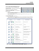
Control Panel LED Sequences Print and cut out this chart to mount on the printer if desired. Suggested location: Top Cover.
Copyright © 2013 ASTRO MACHINE CORP. Elk Grove Village, IL 60007 08/15/2013 Part Number: 200-AJM1, Rev.