
Instruction manual
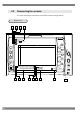
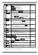
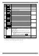

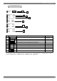
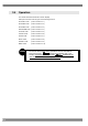
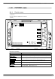
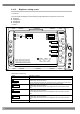
Table Of Contents
- 表紙英語版.pdf
- 中表紙英語版.pdf
- 納品_D0066取扱説明書_第1版(WM-3014).pdf
- INTRODUCTION
- SAFETY PRECAUTIONS
- Concerning the monitor
- ( Do not subject the monitor to strong impact or throw it around. Doing so may cause the liquid crystal to leak and/or the monitor to malfunction, rupture, generate heat and/or cau
- ( Do not use the monitor wherever there is a risk of ignition or explosions.
- ( Do not place the monitor inside a microwave oven or other heating or cooking appliance or pressure vessel. Doing so may cause heat or smoke to be generated in the monitor, combus
- ( Inside the monitor are some high-voltage parts: since exposure to these parts may result in electric shocks or burns and/or malfunctioning, refrain from disassembling, repairing
- ( If a thunderstorm should occur while the monitor is being used outdoors, immediately turn off its power, disconnect the power cable from the main unit, and move the monitor to a
- Concerning the power cord
- Concerning foreign matter
- Concerning the power supply
- ( Use a supply voltage within the range of DC 10V to 18V (5% for the monitor.
- ( In order to avoid malfunctioning and trouble, it is recommended that the accessory AC/DC adapter be used. In the event that another power supply is to be used, ensure that its su
- ( Do not turn the power back on immediately after having turned it off. Doing so can cause malfunctioning.
- ( Bear in mind that if the same DC power supply as microphones, amplifiers, speakers and other audio products should be used for the monitor, the sound may be adversely affected.
- Concerning the liquid crystal
- ( Due to the nature of liquid crystal, some picture elements may be missing (bright spots, flashing spots, etc.) at times.
- ( Do not touch any liquid crystal which has leaked from the liquid crystal panel.
- ( In the event that liquid crystal has made contact with your eyes or mouth, rinse it off with water immediately. If it has come into contact with your skin or clothing, wipe it of
- ( Exercise care with the glass of a broken liquid crystal panel.
- ( The LCD panel is a high-precision component and, as such, the following care must be taken in its handling.
- ( Handle the liquid crystal protective panel carefully.
- Concerning impact
- Concerning the installation and operation locations
- Concerning problems due to the nature of liquid crystal
- ( The liquid crystal's response time, brightness and colors may vary depending on the ambient temperature.
- ( Depending on what is displayed, unevenness in the brightness, flicker, vertical stripes and/or very small flecks may appear.
- ( The optical characteristics of liquid crystal (such as unevenness in the brightness or display) change in accordance with the operating time. These changes are particularly appar
- ( The display colors may change depending on the view angle.
- ( Noise may appear on the startup screen.
- ( Image lag may occur. Avoid displaying the same pattern for a prolonged period of time.
- Concerning the monitor
- 1
- CONCERNING THE WM-3014
- Outline of WM-3014
- ( 6.3-inch a-Si TFT LCD panel featured
- ( HD-SDI, SD-SDI or YPbPr HD analog signals supported as the input
- ( 25 different video formats supported
- ( SDI IN ((2), SDI MONITOR OUT, HD analog input (ANALOG Y, ANALOG Pb, ANALOG Pr) and composite input (NTSC, PAL) connectors provided
- ( Image adjustment functions
- ( Marker displays
- ( Single-action operation for selecting input channels, partial display/non-display of information, picture overlay and freeze/update using the switches on the front panel
- ( Many different display modes available
- ( Compare mode provided
- ( Lighting of red, green LEDs at top of screen using external control (contact supply type)
- ( Loading of preset data enabled by external control (contact supply type)
- ( Preset switches provided on front panel (for loading and saving the preset data)
- ( Automatic tracking of input signals supported
- ( Automatic 1/1.000 and 1/1.001 frame rate tracking and input signal detection functions
- ( Reference input (HD analog tri-level sync, BB_525, BB_625)
- ( CRC error detection function (during HD-SDI input) for input channels
- ( Time code (VITC) display (during HD-SDI input)
- ( Functions for locking the panel switches and storing the settings
- ( Light weight and slim-line dimensions
- ( DC 12V supported (10-18V)
- ( Camera battery supported
- ( 6.3-inch a-Si TFT LCD panel featured
- Outline of WM-3014
- 2
- PARTS AND THEIR FUNCTIONS
- 3
- OPERATION
- 4
- MAIN SPECIFICATIONS
- 5
- STANDARD AND OPTIONAL ACCESSORIES
- 6
- MAINTENANCE AND OTHER PROCEDURES
9
3
3
OPERATION
3.1 Connection procedure
This section describes how to connect the following to the WM-3014.
(1) Connecting the power supply
Check that the monitor's POWER switch is at the OFF position, and connect the Cannon
connector of the AC/DC adapter to the WM-3014's power socket (no.1 on the rear panel view).
Check the shapes of the connector and socket before proceeding with the connections.
(2) Connecting the input signals
When SDI signals are to be input
When SDI signals are to be input, use BNC coaxial cables to make the connections to the SDI IN
connectors.
The SDI IN connectors are where the SDI signals are input; MONITOR OUT is the output
connector which is used for the simplified monitoring of the SDI input signals.
Supply serial signals complying with the BTA S-004B standard as the HD-SDI input signals.
Use a coaxial cable (5C-FB or its equivalent) which can handle the 1.5 GHz band.
Supply serial signals complying with the SMPTE259M (270Mbit/s) standard as the SD-SDI input
signals.
(3) Connecting the remote controller
Check that the monitor's POWER switch is at the OFF position, and connect the remote
controller to the WM-3014's TALLY connector (no.9 on the rear panel view).
Check the shapes of the connector and socket before proceeding with the connections.
3.2 Usage
A protective film is adhered to the surface of the LCD panel. Peel it off before using the WM-3014.
After checking the connections, turn on the power using the POWER switch on the front panel of the
WM-3014. The POWER LED lights, and images are displayed.
If the POWER LED fails to light, check the connections again.
To conduct the simplified monitoring of the SDI input signals, use the MONITOR OUT connector.
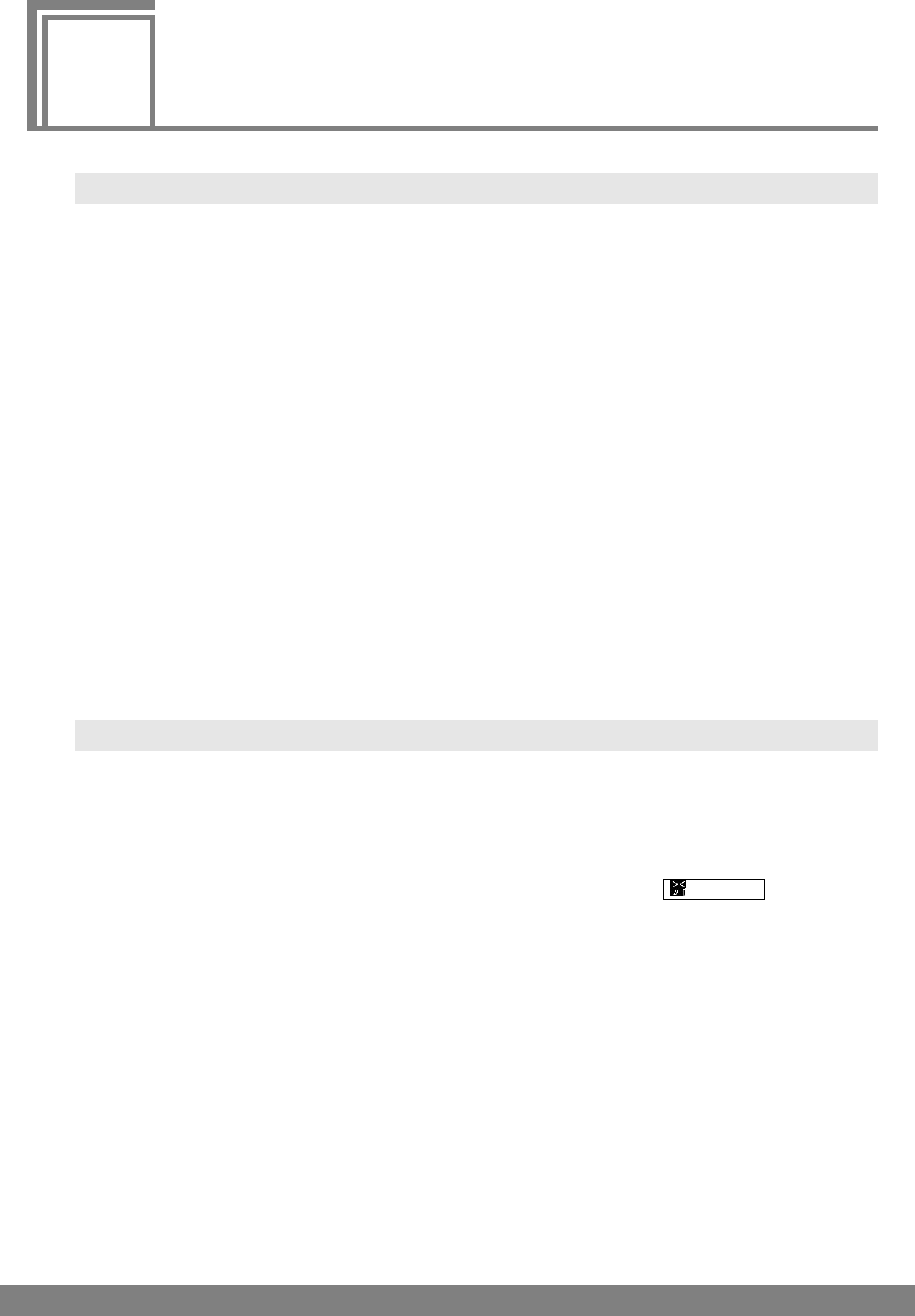
If no input signals are supplied, the image area appears all black, and
NoSignal is displayed in
red on the screen.