
Installation Guide


5
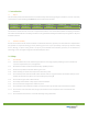
Figure 1. Bolt positions for the at-minimum four-bolts for a) modules CHSM5409M, CHSM6609M/P, CHSM6610M/P; and b) modules CHSM6611P
and CHSM6612P. Solid red arrows indicate primary bolt positions; dashed blue arrows indicate positions where bolts can be added for additional
support.
Bolts are inserted as described in the process below (see gure 2).
1. Place the module on the frame.
2. Insert four stainless-steel bolts (M6) through the holes (7x11.5mm) in the frame according to gure 1. For maximum
security against strong winds and heavy snow, all available mounting holes should be used.
3. Secure each bolt to the frame with 2 stainless-steel washers, one on each side of the mounting structure; and screw on
either a stainless-steel spring washer or a toothed lock washer. Finally, secure with a stainless steel nut (M6).
4. The torque for tightening the nut and bolts recommended 13Nm when the property class of bolts and screws is Class 8,8.
Figure 2. Securing the module with bolts.
3.2.2 Clamping with clamps (aluminum alloy)
Modules can be laid either across the supporting bars (gure 3a) or parallel to them (gure 3b and gure 3c).
(a)
(b)
(a)
(b)