THE POWER OF ASTRONERGY CRYSTALLINE SILICON PV MODULE INSTALLATION GUIDE
CRYSTALLINE SILICON PV MODULE INSTALLATION GUIDE 1. Introduction 1.1 1.2 Purpose Limitation of Liability 2. Safety 2.1 2.2 General Safety Installation Safety 3. Mechanical Installation 3.1 3.2 Installation Condition Installation Methods 4. Electrical Installation 4.1 4.2 Installation Condition Grounding 5.
1. Introduction 1.1 Purpose This document provides detailed instructions and valuable safety information regarding the installation, electrical connection, and maintenance of the following ASTRONERGY Crystalline Photovoltaic modules: CHSM5409M CHSM5611M CHSM5612M CHSM6609M CHSM6606P CHSM6609P CHSM6610P CHSM6611P CHSM6610M CHSM6612M CHSM6612P All instructions and mechanical and electrical requirements should be read and understood before attempting installation.
2.1.12 Keep the PV module packed in the carton until installation. 2.1.13 Do not use modules near equipment or in places where flammable gases may be generated. 2.2 Installation Safety 2.2.1 Wear protective head gear, insulating gloves, safety shoes, and insulated tools when installing the modules. 2.2.2 Do not install the modules in rain, snow, or otherwise wet or windy conditions. 2.2.
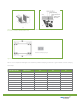
(a) (b) Figure 1. Bolt positions for the at-minimum four-bolts for a) modules CHSM5409M, CHSM6609M/P, CHSM6610M/P; and b) modules CHSM6611P and CHSM6612P. Solid red arrows indicate primary bolt positions; dashed blue arrows indicate positions where bolts can be added for additional support. Bolts are inserted as described in the process below (see figure 2). 1. Place the module on the frame. 2. Insert four stainless-steel bolts (M6) through the holes (7x11.5mm) in the frame according to figure 1.
(c) (d) Figure 3. Illustrations of the three different methods for clamping modules onto the frame with aluminum clamps. Each aluminum mounting clamp comes with an M8 bolt, a plain washer, a spring washer, and an M8 nut. To fasten the module: 1. Lay the module on the two supporting bars (not provided). The bars should be made with stainless material or treated with an anti-corrosion process (e.g., anodic oxidation treatment). 2.
(b) (a) Figure 5. Close-ups of middle (a) and side (b) aluminum clamps. The dimensions for the middle clamps are a ≥ 40 mm, b ≥ 26 mm, c = 8 mm, d ≥ 28 mm, and Ø = 9 mm. Variable clamping range Figure 6. Permitted clamping locations with clamp. For exact dimensions for a given module series, see table 1 (below). Table 1. Use in conjunction with figure 6 to determine permitted clamping locations for a given module series for clamping with clamps.
4. Electrical Installation and Grounding 4.1 Installation 4.1.1 The electrical characteristics are within ±10 percent of the indicated values of Isc. Voc and Pmp under test conditions (irradiance of 100 mW/cm2,AM1.5 spectrum, and a cell temperature of 25°C). 4.1.2 The maximum system voltage for all module series is 600 V for North American Market and 1000V for European Market. 4.1.3 Connect quantity of modules that match the voltage specifications of the inverters used in system.
4.2 Grounding Figure 7. Grounding the aluminum frame with copper wire. 4.2.1 Use the marked 5.5 mm grounding holes (5.5mm) to ground the anodized frame. Use an M5 nut, two M5 cut washers, an M5 plain washer, an M5 spring washer, and an M5 bolt and a copper wire. All nuts, bolts, and washers are type M5 and should be made of stainless steel (as in figure 8). 4.2.2 Put the bolt through the cup washer and wrap the copper wire around the bolt.
SEOUL, KOREA RAVENSBURG, GERMANY BARCELONA, SPAIN SOUTH SAN FRANCISCO, USA TOKYO, JAPAN HANGZHOU,CHINA SHANGHAI,CHINA WENZHOU,CHINA BANGKOK, THAILAND CORPORATE HEADQUARTERS BRANCH OFFICES Chint Solar (ZheJiang) Co., Ltd. 1335 Bin’an Road, Binjiang District Hangzhou, Zhejiang Province, 310053 China Tel: + 86 571 5603 1888 Fax: + 86 571 5603 2383 Spain Chint Solar Hispania S.L. Paseo de Gracia, 78, 2-2A 08008 Barcelona, Spain Tel: + 34 9346 73778 Fax: + 34 9346 73789 Japan KoyoAstro Co., Ltd.