
Installation Manual


8
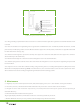
(h )
(g)
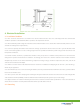
To fasten the module:
a) Place the module on the two supporting bars (not provided). The bars should be made with stainless material and treated
with an anti-corrosion process (e.g., anodic oxidation treatment) or aluminum prole. Each solar PV module needs at least four
clamps to x. Do not make the clamp contact the glass directly or make the aluminum frame deformation in the installation
process, and avoid the shadow of solar PV components.
b) The bar’s top surface contacted with module frame should come with grooves compatible with an M8 bolt.
c) If the bars do not come with grooves, holes of a suitable diameter may need to be drilled to allow bolts to be attached to
the bars at the same locations as mentioned above.
d) Secure each clamp by attaching plain washer, spring washer, and nut, in that order.
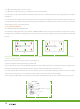
e) Both of close-ups of Figure h,indicating the middle clamps and Figure i, indicating the side clamps forreference. Suggest
the dimensions for middle clamps are: a ≥ 40 mm, b ≥ 26 mm, c = 8 mm, d ≥ 28 mm, and Ø = 9 mm. The torque for tightening
the nut and bolts are recommended 28Nm when the property class of bolts and screws is Class 8.8.
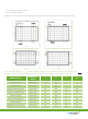
f) Especially for Figure e & Figure g mounting method, the modules may be mounted using clamps designed for solar
modules refer to Figure j, the modules must be supported along the length of the edge, and should overlap the array rail by
10mm – 14mm
(j)
g) Especially for Figure f & Figure g mounting method: the recommended mechanical load on panels is less than 2400Pa, and
this method is not suitable for 35mm and 45mm frame module series. (the dimension C=35 or 45 in Figure k).