
Installation Manual


9
(k)
4. Electrical Installation
4.1 Installation Condition
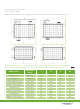
4.1.1 The electrical characteristics are within ±10% of the indicated values of Isc. Voc and Pmpp under the standard test
conditions (irradiance of 1000 W/m2, AM1.5 spectrum, cell temperature of 25
℃
.
4.1.2 The maximum system voltage of all the IEC & UL standard module series is 1000V. The 1500V standard products are also
available according to the requirements
)
.
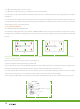
4.1.3 Connect quantity of modules that match the voltage specifications of the inverters used in system. Modules must
not be connected together to create a voltage higher than the permitted maximum system voltage under the lowest local
temperature conditions.
4.1.4 Under normal conditions, a photovoltaic module is likely to experience conditions that produce more current and/or
voltage than reported at standard test conditions. Accordingly, the values of Isc and Voc marked on this module should be
multiplied by a factor of 1.25 when determining component voltage ratings, conductor ampacities, fuse sizes, and size of
controls connected to the PV output.
4.1.5 Refer to Section 690-8 of the National Electrical Code for an additional multiplying factor of 125%
(
80% derating
)
which may be applicable.
4.1.6 Each module (or series-connected string of modules) shall be provided with the maximum series fuse, speci ed 15A for
the 6 inch cell module series.
4.1.7 Use a special solar cable and plugs for installing the PV system and make sure that all connections are safe and tight. The
cable should be 4 mm2 (12AWG), and able to withstand the maximum possible system open-circuit voltage.
4.1.8 Bypass diodes are included in module junction boxes to avoid decreased module performance in the event of shade or
shelter. Please check the relevant product datasheet for the speci c diodes of J-box.
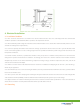
4.2 Grounding