REMOTE CONTROL ENGINE STARTER / SECURITY SYSTEM USER MANUAL Model 3006 For all automatic transmission gas- and diesel-powered vehicles. (FRANÇAIS AU VERSO) CONSULT SAFETY PRECAUTION SECTION BEFORE USING THIS PRODUCT. NEVER INSTALL THIS PRODUCT ON A MANUAL TRANSMISSION VEHICLE. SOME FEATURES MAY REQUIRE ADDITIONAL MATERIAL (NOT INCLUDED). PATENT NOS CAN 1.130.426 USA 4.345.554 - 5.614.883 5.617.819 - 5.673.
<>34; " % GOVERNMENT REGULATIONS This device complies with the requirements of Industry Canada (IC) - Management of Radiofrequencies, as specified in document CNR-210. Its use is authorized only on a no-interference, no-protection basis; in other words, this device must not be used if it is determined that it causes harmful interference to services authorized by IC.
<>34; " % INTRODUCTION Thank you for choosing the Astroflex Remote Starter/Security System. Your System is the result of intensive research by a company specializing in the design of high-quality electronic automotive products. It is designed to provide many years of reliable, trouble-free service. Its advanced microchip circuitry incorporates billions of possible access codes, which makes it virtually impossible to interfere with another remote control vehicle.
<>34; " % SAFETY PRECAUTIONS Before using this product, carefully read the following safety precautions. Immediately report any malfunction to the Astroflex dealer that performed installation. Under no circumstance can this product or its use be modified. Always turn off main switch when vehicle is parked in an enclosed, unventilated area or is in for servicing. Always turn off main switch when not using your Remote Starter for extended periods of time.
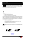
<>34; " % THE REMOTE CONTROL Your remote control has been designed to fit the natural contours of your hands so that it is easier to use. It is powered by long-life lithium batteries. It can control two vehicles separately. Up to three additional remote controls can be assigned to your vehicle. See your dealer for replacement batteries or additional remote controls.
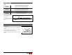
<>34; " % Legend : Pressing Preamble Transmission Confirmation Another confirmation is sent by your remote when you activate “Panic” mode. This confirmation indicates whether a button was pressed by mistake and also confirms button was pressed correctly. To transmit on channel 2, you must press button again within half a second for command to be transmitted properly. This confirmation indicates how long a button must be held down for a command to be transmitted properly (one second duration).
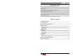
<>34; " % COMMANDS FOR 3006 COMMANDS BUTTONS (PICTOGRAM) PANIC START / CONTINUOUS MODE CONFIRMATION HORN LIGHTS SIREN 30 / 60 SEC. 30 / 60 SEC. 30 / 60 SEC. 1♥ 1 STOP ♠ 1 LOCK / ARM 1 1 UNLOCK / DISARM 2 2 TRUNK 3 4/2/3 ♣ ACTIVATE / DEACTIVATE SENTINEL MODE ACTIVATE / DEACTIVATE UTILITY # 1 1 ACTIVATE / DEACTIVATE UTILITY # 2 1 RUNTIME ADJUSTMENT 1-4 PRESET TEMPERATURE ADJUSTMENT 1-4 CAR FINDER 7 DISPLAY REMOTE START FAIL CODES 3 1 – 15 ♥.
<>34; " % START COMMANDS STARTING THE ENGINE To start the engine, press button (horn: 0, lights: 1). The system automatically adjusts ignition duration for your type of vehicle; parking lights flash once (duration: four seconds) then stay on all the time engine is running. If more than one command is emitted, each successive start command resets runtime to the beginning, parking lights flash once to confirm command has been received and horn sounds once to let you know engine is already running.
<>34; " % TRIGGER INPUT Your remote starter is equipped with a negative trigger (pulse) input. This input (enabled during installation) can be connected to another remote control device or to a timer output. If this input is connected, consult this device's manual or ask your technician which command controls the start/stop function. The start/stop commands received on this input are ignored while the engine is running on a remote start.
<>34; " % LOW TEMPERATURE MODE In Low Temperature (previously called Sentinel) mode, system starts your engine automatically when temperature falls below a preset level. Engine will run for programmed runtime, after which system will wait 2½ hours and then start engine again if temperature is still below preset level. To activate/deactivate Low Temperature mode, press and buttons simultaneously.
<>34; " % SECURITY SYSTEM SECURITY ZONES Your security system can use up to six different monitoring devices at the same time to protect your vehicle. These devices are connected to the control module on different inputs called security zones. One of these zones can give an audible warning (siren "ON" for 2 seconds) while the other five generate an alarm condition if the system is armed.
<>34; " % OPERATION Your vehicle safety system can function in three different modes, namely manual, semi-automatic and automatic depending on the initial programming. Consult the section corresponding to the mode in which your system was configured during installation. MANUAL In manual mode, the security system must be armed and disarmed with the remote control. Consult the table of command on page 5. The system is armed as soon as the command is received.
<>34; " % The following table shows how each zone affects the rearming cycle. Security zone Hood Doors Additional sensor Shock sensors Effect on the rearming cycle These four zones delay the onset of the rearming cycle for as long as they remain in a violation status.
<>34; " % INDICATOR LIGHT The indicator light indicates the different alarm system conditions. When it is mounted in a place where it is visible from outside the vehicle, it may also act as a deterrent. UPON ARMING - The indicator light displays the codes for the zones in violation (example, a door is open). Only one code is displayed at a time. If more than one zone is in violation during arming, the code changes when the zone displayed is corrected (example, the door is closed).
<>34; " % VALET SWITCH The Valet switch is used to activate the Valet mode or cancel an alarm condition when your Remote control is not available (lost, weak batteries, etc). This switch must be located in a hidden location known only to regular users of the vehicle. Ask your installer to show you where it is located. VALET MODE This mode is used to disarm the alarm permanently when your vehicle is in for servicing, for example. The following sequence will inactivate the alarm system permanently.
<>34; " % PARKING LIGHTS The parking lights flash intermittently (repeated flashes) when there is a warning, pre-alarm or alarm condition. The parking lights also confirm that commands have been received. See the table in the CONFIRMATION section. IN VIOLATION “In violation” means the condition required for a security zone to generate an alarm condition; for example, a door is open, etc.
<>34; " % TRUNK RELEASE Press received. button (lights: 3). Trunk is released and parking lights flash three times to confirm command has been Trunk cannot be released if alarm is armed (if applicable) or if ignition key is in “ON” position. In both these cases, parking lights flash once to confirm that command has been received but trunk could not be released. If you are not sure you have received confirmation, repeat command. System will repeat confirmation as often as you wish.
<>34; " % TO ACCESS VALET MODE, carry out “DISARMING“ sequence then, within 20 seconds, place the Valet switch to “ON“ position. If Valet switch is placed in “ON“ position more than 20 seconds following disarming sequence, you will need to turn ignition key to the “OFF“ position and then repeat the sequence from the beginning. Note that the antitheft system will not rearm as long as the Valet mode is not deactivated.
<>34; " % UTILITY COMMANDS Programmable as Active or Inactive during installation. Two additional commands control most of your vehicle’s accessories, depending on which were connected during installation (headlight, defroster, etc.). For details, consult your technician. COMMAND #1 To activate this function, press and buttons simultaneously (lights: 1).
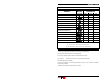
<>34; " % START FAIL CODES When a remote start attempt fails, it is possible to determine what caused the failure to start. Press the and buttons simultaneously. The number of times the parking lights flash corresponds to the start fail code. The table below lists the various start fail codes. Code Failure to start details 1 Module has received a Stop command (remote or timer). 2 Brakes have been applied during or after start sequence. 3 Stop command sent by alarm system.
<>34; " % SAFETY CHECKS In order to maintain a high safety standard, proceed with following routine checks every month. HOOD SWITCH Start your vehicle with Remote Starter. Open hood. Engine should stop as soon as hood is opened. If engine does not stop immediately, turn main switch to “OFF” position and leave it off until situation has been corrected. Contact your local service center. DETECTING “P” AND “N” GEARSHIFT POSITIONS Your starter is designed to check gearshift position at all times.
<>34; " % LIMITED LIFETIME WARRANTY ASTROSTART remote starters Astroflex Inc.