Motherboard Z170M-PLUS
E10768 First Edition August 2015 Copyright © 2015 ASUSTeK COMPUTER INC. All Rights Reserved. No part of this manual, including the products and software described in it, may be reproduced, transmitted, transcribed, stored in a retrieval system, or translated into any language in any form or by any means, except documentation kept by the purchaser for backup purposes, without the express written permission of ASUSTeK COMPUTER INC. (“ASUS”).
Contents Safety information....................................................................................... iv About this guide.......................................................................................... iv Package contents........................................................................................ vi Z170M-PLUS specifications summary....................................................... vi Chapter 1: Product introduction 1.1 Before you proceed..........................
Safety information Electrical safety • To prevent electrical shock hazard, disconnect the power cable from the electrical outlet before relocating the system. • When adding or removing devices to or from the system, ensure that the power cables for the devices are unplugged before the signal cables are connected. If possible, disconnect all power cables from the existing system before you add a device.
Where to find more information Refer to the following sources for additional information and for product and software updates. 1. ASUS websites The ASUS website provides updated information on ASUS hardware and software products. Refer to the ASUS contact information. 2. Optional documentation Your product package may include optional documentation, such as warranty flyers, that may have been added by your dealer. These documents are not part of the standard package.
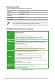
Package contents Check your motherboard package for the following items. Motherboard ASUS Z170M-PLUS motherboard Cables 2 x Serial ATA 6.0 Gb/s cables Accessories 1 x I/O Shield 1 x M.2 screw package Application DVD Support DVD Documentation User Guide If any of the above items is damaged or missing, contact your retailer.
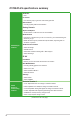
Z170M-PLUS specifications summary Multi-GPU Support Supports AMD® Quad-GPU CrossFireX™ Technology Realtek® ALC887 7.
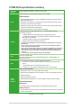
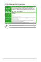
Z170M-PLUS specifications summary ASUS EPU - EPU PC Cleaner - Fast and easy way to get rid of unnecessary junk files USB 3.0 Boost - Featuring speedy USB 3.0 transmission Gaming Scenario eSports Champions - Audio Features - Audio that roars on the battlefield Media Streamer - Pipe music or movies from your PC to a smart TV, your entertainment goes wherever you go! - Media Streamer app for portable smart phone/tablet, supporting iOS 7 & Android 4.
Z170M-PLUS specifications summary ASUS Exclusive Overclocking Features ASUS Quiet Thermal Solution SFS (Stepless Frequency Selection) - BCLK/PCIE frequency tuning from 40MHz up to 170MHz at 0.
Z170M-PLUS specifications summary BIOS features 128 Mb Flash ROM, UEFI AMI BIOS, PnP, DMI 3.0, WfM2.0, SM BIOS 3.0, ACPI 5.0, Multi-language BIOS, ASUS EZ Flash 3, ASUS CrashFree BIOS 3, F11 EZ Tuning Wizard, F6 Qfan Control, F3 My Favorites, Quick Note, Last Modified Log, F12 PrintScreen function, and ASUS DRAM SPD (Serial Presence Detect) memory information Manageability WfM 2.0, DMI 3.
Product introduction 1.1 Before you proceed 1 Take note of the following precautions before you install motherboard components or change any motherboard settings. 1.2 • Unplug the power cord from the wall socket before touching any component. • Before handling components, use a grounded wrist strap or touch a safely grounded object or a metal object, such as the power supply case, to avoid damaging them due to static electricity.
Place this side towards the rear of the chassis Z170M-PLUS 1.2.3 Motherboard layout 1 2 3 4 5 6 22.7cm(8.95in) KBMS CPU_FAN DIGI +VRM EATXPWR USB3_12 SATA6G_1 PCIEX16_1 PCIEX1_1 BATTERY Intel® Z170 Super I/O PCIEX1_2 ALC 887 SATAEXPRESS Z170M-PLUS Intel® I219V 128Mb BIOS PCIEX16_2 SPDIF_OUT LPT COM SB_PWR USB1112 USB1314 USB3_34 SATA6G_5 SATA6G_6 AAFP 15 1-2 7 SATA6G_2 CHA_FAN2 CHA_FAN1 SATA6G_3 SATA6G_4 AUDIO 1 M.2(SOCKET3) LAN_USB_910 LANGuard USB3_78 24.4cm(9.
1.2.4 Layout contents Connectors/Jumpers/Slots/LED 1. ATX power connectors (24-pin EATXPWR, 8-pin ATX12V) 2. CPU, chassis fan connectors (4-pin CPU_FAN, 4-pin CHA_FAN1~2) 3. Intel® LGA1151 CPU socket 4. M.2 Socket 3 5. DDR4 DIMM slots 6. Standby power LED (SB_PWR) 7. USB 3.0 connectors (20-1 pin USB3_12, USB3_34) 8. Intel® Z170 Serial ATA 6.0Gb/s connectors (7-pin SATA 6G_1~6, SATA EXPRESS) 9. System panel connector (20-5 pin PANEL) 10. Clear RTC RAM (2-pin CLRTC) 11. USB 2.
1.3 Central Processing Unit (CPU) This motherboard comes with a surface mount LGA1151 socket designed for the 6th Generation Intel® Core™ i7 / Core™ i5 / Core™ i3, Pentium® and Celeron® processors. Z170M-PLUS Z170M-PLUS CPU socket LGA1151 Unplug all power cables before installing the CPU. 1-4 • Ensure that you install the correct CPU designed for the LGA1151 socket only. DO NOT install a CPU designed for LGA1150, LGA1155 and LGA1156 sockets on the LGA1151 socket.
1.3.
1.3.2 CPU heatsink and fan assembly installation Apply the Thermal Interface Material to the CPU heatsink and CPU before you install the heatsink and fan if necessary.
To uninstall the CPU heatsink and fan assembly 2 1 A B B A 1.4 System memory 1.4.1 Overview This motherboard comes with four Double Data Rate 4 (DDR4) Dual Inline Memory Module (DIMM) sockets. A DDR4 module is notched differently from a DDR, DDR2 or DDR3 module. DO NOT install a DDR, DDR2, or DDR3 memory module to the DDR4 slot. The figure illustrates the location of the DDR4 DIMM sockets: DIMM_B1 DIMM_B2 DIMM_A1 DIMM_A2 According to Intel® CPU spec, DIMM voltage below 1.
1.4.2 Memory configurations You may install 2 GB, 4 GB, 8 GB and 16 GB unbuffered non-ECC DDR4 DIMMs into the DIMM sockets. Recommended memory configurations 1-8 • You may install varying memory sizes in Channel A and Channel B. The system maps the total size of the lower-sized channel for the dual-channel configuration. Any excess memory from the higher-sized channel is then mapped for single-channel operation.
1.4.
1.5 Expansion slots In the future, you may need to install expansion cards. The following sub‑sections describe the slots and the expansion cards that they support. Unplug the power cord before adding or removing expansion cards. Failure to do so may cause you physical injury and damage motherboard components. 1.5.1 Installing an expansion card To install an expansion card: 1.
PCI Express operating mode VGA configuration PCIe 3.0 x16_1 (gray) PCIe 3.0 x16_2 Single VGA/PCIe card x16 (Recommended for single VGA card) N/A Dual VGA/PCIe cards x16 x4 • In single VGA card mode, use the PCIe 3.0 x16_1 slot (gray) for a PCI Express x16 graphics card to get better performance. • We recommend that you provide sufficient power when running CrossFireX™ mode.
1.6 1. Headers Clear RTC RAM (2-pin CLRTC) This header allows you to clear the Real Time Clock (RTC) RAM in CMOS. You can clear the CMOS memory of date, time, and system setup parameters by erasing the CMOS RTC RAM data. The onboard button cell battery powers the RAM data in CMOS, which include system setup information such as system passwords. +3V_BAT GND CLRTC Z170M-PLUS PIN 1 Z170M-PLUS Clear RTC RAM To erase the RTC RAM: 1-12 1. Turn OFF the computer and unplug the power cord. 2.
1.7 Connectors 1.7.1 Rear panel connectors 1 2 12 11 3 10 9 8 4 5 6 7 1. PS/2 mouse port (green). This port is for a PS/2 mouse. 2. Video Graphics Adapter (VGA) port. This 15-pin port is for a VGA monitor or other VGA-compatible devices. 3. LAN (RJ-45) port. This port allows Gigabit connection to a Local Area Network (LAN) through a network hub.
Audio 2.1, 4.1, 5.1, or 7.1-channel configuration Port Light Blue (Rear panel) Lime (Rear panel) Pink (Rear panel) Lime (Front panel) Headset 2.1-channel 4.1-channel 5.1-channel 7.1-channel Line In Rear Speaker Out Rear Speaker Out Rear Speaker Out Line Out Mic In - Front Speaker Out Mic In - Front Speaker Out Bass/Center - Front Speaker Out Bass/Center Side Speaker Out To configure an 7.1-channel audio output: Use a chassis with HD audio module in the front panel to support an 7.
1.7.2 1. Internal connectors Serial port connector (10-1 pin COM) This connector is for a serial (COM) port. Connect the serial port module cable to this connector, then install the module to a slot opening at the back of the system chassis. PIN 1 DCD TXD GND RTS RI RXD DTR DSR CTS COM Z170M-PLUS Z170M-PLUS Serial port (COM) connector The COM module is purchased separately. 2. USB 2.0 connectors (10-1 pin USB1112, USB1314) These connectors are for USB 2.0 ports.
3. USB 3.0 connectors (20-1 pin USB3_12, USB3_34) These connectors allow you to connect a USB 3.0 module for additional USB 3.0 front or rear panel ports. With an installed USB 3.0 module, you can enjoy all the benefits of USB 3.0 including faster data transfer speeds of up to 5 Gbps, faster charging time for USB-chargeable devices, optimized power efficiency, and backward compatibility with USB 2.0.
4. ATX power connectors (24-pin EATXPWR, 8-pin ATX12V) These connectors are for ATX power supply plugs. The power supply plugs are designed to fit these connectors in only one orientation. Find the proper orientation and push down firmly until the connectors completely fit.
5. Front panel audio connector (10-1 pin AAFP) NC AGND NC NC SENSE2_RETUR AGND NC SENSE1_RETUR This connector is for a chassis-mounted front panel audio I/O module that supports either HD Audio or legacy AC`97 audio standard. Connect one end of the front panel audio I/O module cable to this connector.
7. M.2 socket 3 This socket allows you to install an M.2 (NGFF) SSD module. M.2(SOCKET3) Z170M-PLUS Z170M-PLUS M.2(SOCKET3) • This socket supports M Key and 2242/2260/2280 storage devices. • The M.2 slot supports data transfer speed up to 32Gb/s. • M.2 socket and SATA Express connector support PCIe and SATA devices in PCIe and SATA modes. • hen a device in PCIe mode is installed on the M.2 socket, SATA Express supports W devices in both PCIe and SATA modes.
8. Digital audio connector (4-1 pin SPDIF_OUT) Z170M-PLUS SPDIFOUT GND +5V This connector is for an additional Sony/Philips Digital Interface (S/PDIF) port. Connect the S/PDIF Out module cable to this connector, then install the module to a slot opening at the back of the system chassis. PIN 1 SPDIF_OUT Z170M-PLUS Digital audio connector 9.
11. Intel® Z170 Serial ATA 6.0Gb/s connectors (7-pin SATA6G_1~6, SATAEXPRESS) These connectors connect to Serial ATA 6.0 Gb/s hard disk drives via Serial ATA 6.0 Gb/s signal cables.
12. System panel connector (20-5 pin PANEL) This connector supports several chassis-mounted functions. PANEL Z170M-PLUS +HDD_LED- RESET PLED- HDD_LED+ HDD_LEDGND Reset NC PLED+ PIN 1 SPEAKER +5V Ground Ground Speaker PWR_SW PLED+ PLEDPWR Ground +PWR_LED- +PWR_LED- * Requires an ATX power supply Z170M-PLUS System panel connector • System power LED (4-pin +PWR_LED-) This 2-pin connector is for the system power LED. Connect the chassis power LED cable to this connector.
1.8 1. Onboard LED Standby Power LED (SB_PWR) The motherboard comes with a standby power LED that lights up to indicate that the system is ON, in sleep mode, or in soft-off mode. This is a reminder that you should shut down the system and unplug the power cable before removing or plugging in any motherboard component. The illustration below shows the location of the onboard LED.
1.9 Software support 1.9.1 Installing an operating system This motherboard supports Windows® 7 (64-bit/32-bit), Windows® 8.1 (64-bit) and Windows® 10 (64-bit) Operating Systems (OS). Always install the latest OS version and corresponding updates to maximize the features of your hardware. Motherboard settings and hardware options vary. Refer to your OS documentation for detailed information. 1.9.
BIOS information 2.1 Managing and updating your BIOS 2 Save a copy of the original motherboard BIOS file to a USB flash disk in case you need to restore the BIOS in the future. Copy the original motherboard BIOS using the ASUS Update utility. 2.1.1 EZ Update EZ Update is a utility that allows you to automatically update your motherboard’s softwares, drivers and the BIOS version easily. With this utlity, you can also manually update the saved BIOS and select a boot logo when the system goes into POST.
2.1.2 ASUS EZ Flash 3 The ASUS EZ Flash 3 feature allows you to update the BIOS without using an OS‑based utility. • Ensure that you load the BIOS default settings to ensure system compatibility and stability. Select the Load Optimized Defaults item under the Exit menu. See section 2.10 Exit Menu for details. • Check your Internet connection before updating the BIOS via the Internet. To update the BIOS using EZ Flash 3: 1. Enter the Advanced Mode of the BIOS setup program.
3. Reboot the system when the update process is done. 2.1.3 • ASUS EZ Flash 3 supports USB devices, such as a USB flash disk, with FAT 32/16 format and single partition only. • DO NOT shut down or reset the system while updating the BIOS to prevent system boot failure! ASUS CrashFree BIOS 3 utility The ASUS CrashFree BIOS 3 is an auto recovery tool that allows you to restore the BIOS file when it fails or gets corrupted during the updating process.
Before updating BIOS • Prepare the motherboard support DVD and a USB flash drive. • Download the latest BIOS file and BIOS Updater from http://support.asus.com and save them in your USB flash drive. NTFS is not supported under FreeDOS environment. Ensure that your USB flash drive is in single partition and in FAT32/16 format. • Turn off the computer. • Ensure that your computer has a DVD optical drive. Booting the system in DOS environment To boot the system in DOS: 1.
Updating the BIOS file To update the BIOS file: 1. On the FreeDOS prompt, type bupdater /pc /g and press . D:/> bupdater /pc /g 2. On the BIOS Updater screen, press to switch from Files panel to Drives panel then select D:. ASUSTeK BIOS Updater for DOS V1.30 [2014/01/01] Current ROM BOARD: Z170M-PLUS VER: 0205 (H :00 B :00) DATE: 12/27/2089 PATH: Drives panel Update ROM BOARD: Unknown VER: Unknown DATE: Unknown C:\ C: D: FORMAN~1 Z170MP.
2.2 BIOS setup program Use the BIOS Setup program to update the BIOS or configure its parameters. The BIOS screens include navigation keys and brief online help to guide you in using the BIOS Setup program. Entering BIOS Setup at startup To enter BIOS Setup at startup: Press or during the Power-On Self Test (POST). If you do not press or , POST continues with its routines. Entering BIOS Setup after POST To enter BIOS Setup after POST: Press ++ simultaneously.
2.2.1 EZ Mode By default, the EZ Mode screen appears when you enter the BIOS setup program. The EZ Mode provides you an overview of the basic system information, and allows you to select the display language, system performance mode, fan profile and boot device priority. To access the Advanced Mode, click Advanced Mode(F7) or press . The default screen for entering the BIOS setup program can be changed. Refer to the Setup Mode item in section 2.8 Boot menu for details.
2.2.2 Advanced Mode The Advanced Mode provides advanced options for experienced end-users to configure the BIOS settings. The figure below shows an example of the Advanced Mode. Refer to the following sections for the detailed configurations. To access the EZ Mode, click EzMode(F7) or press .
Menu bar The menu bar on top of the screen has the following main items: My Favorites For saving the frequently-used system settings and configuration Main For changing the basic system configuration Ai Tweaker For changing the overclocking settings Advanced For changing the advanced system settings Monitor For displaying the system temperature, power status, and changing the fan settings Boot For changing the system boot configuration Tool For configuring options for special functions Exit F
Search on FAQ Move your mouse over this button to show a QR code. Scan this QR code with your mobile device to connect to the ASUS BIOS FAQ web page. You can also scan the QR code below. Quick Note (F9) This button above the menu bar allows you to key in notes of the activities that you have done in BIOS. • The Quick Note function does not support the following keyboard functions: delete, cut, copy and paste. • You can only use the alphanumeric characters to enter your notes.
2.2.3 QFan Control The QFan Control allows you to set a fan profile or manually configure the operating speed of your CPU and chassis fans.
Configuring fans manually Select Manual from the list of profiles to manually configure your fans’ operating speed. Speed points Click to manually configure your fans To configure your fans: 2-12 1. Select the fan that you want to configure and to view its current status. 2. Click and drag the speed points to adjust the fans’ operating speed. 3. Click Apply to save the changes then click Exit (ESC).
2.2.4 EZ Tuning Wizard EZ Tuning Wizard allows you to overclock your CPU and DRAM, computer usage, and CPU fan to their best settings. You can also easily set RAID in your system using this feature. RAID setup Tuning your system settings To tune your settings: 1. Press on your keyboard or click EZ Tuning Wizard screen, then click Next. from the BIOS screen to open 2. Select a PC scenario Daily Computing or Gaming/Media Editing, then click Next. 3.
Creating RAID To create RAID: 2-14 1. Press on your keyboard or click EZ Tuning Wizard screen. 2. Click RAID then click Next. from the BIOS screen to open • Ensure that your HDDs have no existing RAID volumes. • Ensure to connect your HDDs to Intel® SATA connectors. 3. The available HDDs display. Click Next to continue. 4. Select the type of storage for your RAID Easy Backup or Super Speed, then click Next.
a. For Easy Backup, select from Easy Backup (RAID1) or Easy Backup (RAID10) then click Next. You can only select Easy Backup (RAID 10) if you connect four (4) HDDs. b. For Easy Backup, select from Super Speed (RAID0) or Super Speed (RAID5) then click Next. 5. After selecting the type of RAID, click Yes to continue the RAID setup. 6. After the RAID setup is done, click Yes to exit the setup then click OK to reset your system.
2.3 My Favorites MyFavorites is your personal space where you can easily save and access your favorite BIOS items.
Adding items to My Favorites To add BIOS items: 1. Press on your keyboard or click Setup Tree Map screen. from the BIOS screen to open 2. On the Setup Tree Map screen, select the BIOS items that you want to save in MyFavorites screen. Main menu panel Selected shortcut items Submenu panel 3. Select an item from main menu panel, then click the submenu that you want to save as favorite from the submenu panel and click .
2.4 Main menu The Main menu screen appears when you enter the Advanced Mode of the BIOS Setup program. The Main menu provides you an overview of the basic system information, and allows you to set the system date, time, language, and security settings. 2.4.1 System Language [English] Allows you to choose the BIOS language version from the options. Configuration options: [English] [Español] [Русский] [한국어] 2.4.2 Security The Security menu items allow you to change the system security settings.
Administrator Password If you have set an administrator password, we recommend that you enter the administrator password for accessing the system. To set an administrator password: 1. Select the Administrator Password item and press . 2. From the Create New Password box, key in a password, then press . 3. Confirm the password when prompted. To change an administrator password: 1. Select the Administrator Password item and press . 2.
2.5 Ai Tweaker menu The Ai Tweaker menu items allow you to configure overclocking-related items. Be cautious when changing the settings of the Ai Tweaker menu items. Incorrect field values can cause the system to malfunction. The configuration options for this section vary depending on the CPU and DIMM model you installed on the motherboard. Scroll down to display other BIOS items. 2.5.
BCLK Frequency [Auto] This item appears only when you set Ai Overclock Tuner to [Manual] and allows you to set the BCLK (base clock) frequency to enhance the system performance. Use the <+> / <-> to adjust the value. The values range from 40.0 MHz to 500.0 MHz. We recommend you to set the value based on the CPU specification, as high BCLK frequencies may damage the CPU permanently.
If you assign a value for 4-Core Ratio Limit, do not set the 1-Core Ratio Limit, 2-Core Ratio Limit, and 3-Core Ratio to [Auto]. 2.5.4 BCLK Frequency: DRAM Frequency Ratio [Auto] Allows you to set the CPU bus speed to DRAM speed ratio mode. [Auto] DRAM speed is set to the optimized settings. [100:133] The BCLK frequency to DRAM speed ratio is set to 100:133. [100:100] The BCLK frequency to DRAM speed ratio is set to 100:100. 2.5.
2.5.8 EPU Power Saving Mode [Disabled] ASUS EPU (Energy Processing Unit) sets the CPU in its minimum power consumption settings. Enable this item to set lower CPU VCCIN and Vcore voltages and achieve the best energy saving condition. Configuration options: [Disabled] [Enabled] 2.5.9 CPU SVID Support [Auto] Disabling SVID Support stops the processor from commmunicating with the external voltage regulator. Configuration options: [Auto] [Disabled] [Enabled] 2.5.
Fixed CPU VRM Switching Frequency (KHz) [250] This item allows you to set a higher frequency for a quicker transient response speed. Use the <+> and <-> keys to adjust the value. The values range from 300KHz to 600KHz with a 50KHz interval. CPU Power Duty Control [T.Probe] DIGI + VRM Duty control adjusts the current and thermal conditions of every component’s phase. [T. Probe] Select to maintain the VRM thermal balance. [Extreme] Select to maintain the current VRM balance.
DO NOT remove the thermal module. The thermal conditions should be monitored. The following item appears only when you set the CPU Graphics to [Manual]. Fixed VCCGT Switching Frequency (KHz) [250] This item allows you to set a higher frequency for a quicker transient response speed. Use the <+> and <-> keys to adjust the value. The values range from 300KHz to 600KHz with a 50KHz interval. GT Power Duty Control [T.Probe] This item adjusts the current and thermal conditions of every component’s phase. [T.
Turbo Mode Parameters Long Duration Package Power Limit [Auto] Allows you to limit the Turbo Ratio’s time duration that exceeds the TDP (Thermal Design Power) for maximum performance. Use the <+> or <-> keys to adjust the value. The values range from 1 W to 4095 W. Package Power Time Window [Auto] Also known as Power Limit 1, this item allows you to maintain the time window for Turbo Ratio over TDP (Thermal Design Power). Use the <+> or <-> keys to adjust the value.
2.5.18 CPU Core/Cache Voltage [Auto] This item allows you to configure the amount of voltage fed to the CPU cores. Increase the voltage when setting a high Core Frequency value. Configuration options: [Auto] [Manual Mode] [Offset Mode] [Adaptive Mode] • The following item appears only when you set the CPU Core/Cache Voltage to [Manual Mode]. • [Adaptive Mode] is available for some specific CPU types. CPU Core Voltage Override [Auto] Allows you to set the CPU Core Voltage override.
2.5.19 DRAM Voltage [Auto] Allows you to set the DRAM Voltage for the sytem memory. The values range from 1.000V to 1.800V with a 0.005V interval. 2.5.20 CPU VCCIO Voltage [Auto] Allows you to set the value for the VCCIO voltage. The values range from 0.700V to 1.585V with a 0.005V interval. 2.5.21 CPU System Agent Voltage [Auto] Allows you to set the value for the CPU system agent voltage. Use the <+> or <-> keys to adjust the value.The values range from 0.700V to 1.685V with a 0.005V interval. 2.
2.5.24 DRAM REF Voltage Control [Auto] This item allows you to set the DRAM reference voltage on the control lines from the memory bus. You can use the <+> or <-> keys to adjust the value. The values range from 0.39500V to 0.63000V with a 0.00500V interval. DRAM DATA REF Voltage on CHA [Auto] Allows you to set the DRAM DATA REF Voltage on CHA. The values range from 0.39500x to 0.63000x with a 0.00500x interval DRAM DATA REF Voltage on CHB [Auto] Allows you to set the DRAM DATA REF Voltage on CHB.
2.6 Advanced menu The Advanced menu items allow you to change the settings for the CPU and other system devices. Be cautious when changing the settings of the Advanced menu items. Incorrect field values can cause the system to malfunction. 2.6.1 CPU Configuration The items in this menu show the CPU-related information that the BIOS automatically detects. The items shown in submenu may be different due to the CPU you installed.
Active Processor Cores [All] This item allows you to select the number of CPU cores to activate in each processor package. Configuration options: [All] [1] [2] [3] For some CPU types, only [All] and [1] appear. Intel Virtualization Technology [Enabled] When set to [Enabled], a VMM can utilize the additional hardware capabilities provided by Vanderpool Technology.
The following items appear only when you set the CPU C-States to [Enabled]. Enhanced C states [Enabled] This item allows your CPU to reduce power consumption when the system is in idle mode. Configuration options: [Enabled] [Disabled] CPU C3/C6 Report [Enabled] Allows you to disable or enable the CPU C3/C6 report to OS. Configuration options: [Enabled] [Disabled] Package C State Limit [Auto] This item allows you to set the a C-state support for the CPU package.
SA - PCI Express options DMI Link ASPM Control [Disabled] This item allows you to control the Active State Power Management on both CPU and PCH (platform controller hub) Both DMI link ASPM control items of the CPU and PCH sides must be enabled for the ASPM to take effect. Configuration options: [Disabled] [L1] PEG ASPM [Disabled] This item allows you to select the ASPM state for energy-saving conditions, or use the ASUS optimized energy saving profile.
PEG Port Configuration Allows you to configure the PEG Port settings. PCIEx16_1 Link Speed [Auto] Allows you to configure the PCIEx16 speed for slot 1. Configuration options: [Auto] [Gen1] [Gen2] [Gen3] Memory Configuration Allows you to configure the memory configuration parameters. Memory Remap [Enabled] Set this item to [Enabled] to support DRAM address remapping for 64-bit operating systems. Configuration options: [Enabled] [Disabled] 2.6.
The following items appear only when you set the SATA Mode Selection to [RAID]. CR#1/2/3 RST Pcie Storage Remapping [Disabled] This item allows you to enable or disable the RST Pcie Storage Remapping feature. Configuration options: [Auto] [Disabled] [Enabled] Alternate ID [Disabled] This item allows you to enable or disable the report for the alternate device ID.
USB Port Disable Override Allows you to selectively enable/disable the corresponding USB port from reporting a Device Connection to the controller. USB_C1 [Enabled] Allows you to enable/disable USB_C1 port. Configuration options: [Disabled] [Enabled] USB_1112/1314 [Enabled] Allows you to enable/disable USB_1112/1314 port. Configuration options: [Disabled] [Enabled] USB3_12/34/78 [Enabled] Allows you to enable/disable USB3_12/34/78 port. Configuration options: [Disabled] [Enabled] 2.6.
Intel PXE Option ROM [Off] This item appears only when you set the previous item to [Enabled] and allows you to enable or disable the PXE OptionRom of the Intel LAN controller. Configuration options: [On] [Off] Serial Port Configuration The sub-items in this menu allow you to set the serial port configuration. Serial Port [On] Allows you to enable or disable the serial port (COM).
Restore AC Power Loss [Power Off] [Power On] The system goes into on state after an AC power loss. [Power Off] The system goes into off state after an AC power loss. [Last State] The system goes into either off or on state, whatever the system state was before the AC power loss. Power On By PS/2 Keyboard [Disabled] [Disabled] Disables the Power On by a PS/2 keyboard. [Space Bar] Sets the Space Bar on the PS/2 keyboard to turn on the system.
2.7 Monitor menu The Monitor menu displays the system temperature/power status, and allows you to change the fan settings. Scroll down to display the other BIOS items. 2.7.1 CPU/ MB Temperature [xxxºC/xxxºF]/ [Ignore] The onboard hardware monitor automatically detects and displays the CPU and motherboard temperatures. Select [Ignore] if you do not wish to display the detected temperatures. 2.7.
2.7.4 Q-Fan Configuration Ofan Tuning Click this item to automatically detect the lowest speed and configure the minimum duty cycle for each fan. CPU Q-Fan Control [Auto] [Auto] Detects the type of CPU fan installed and automatically switches the mode control. [Disabled] Disables the Q-Fan control. [DC Mode] Enables the CPU Q-Fan control feature in DC mode for 3-pin CPU fan. [PWM Mode] Enables the CPU Q-Fan control feature in PWM mode for 4-pin CPU fan.
CPU Fan Min. Duty Cycle(%) [20] Use the <+> and <-> keys to adjust the minimum CPU fan duty cycle. The values range from 20% to 100%. When the CPU temperature is under the lower limit, the CPU fan will operate at the minimum duty cycle. 2.7.5 Chassis Fan 1/2 Q-Fan Control [DC Mode] [PWM mode] Enables the chassis Q-Fan control in PWM mode for 4-pin chassis fan. [DC mode] Enables the chassis Q-Fan control in DC mode for 3-pin chassis fan. [Disabled] Disables the chassis Q-Fan control feature.
Chassis Fan 1/2 Lower Temperature [40] Use the <+> or <-> keys to adjust the chassis fans’ lower temperature. The values range from 40°C to 75°C. Chassis Fan 1/2 Min. Duty Cycle(%) [60] Use the <+> or <-> keys to adjust the minimum chassis fan duty cycle. The values range from 60% to 100%. When the CPU temperature is under the lower limit, the chassis fan operates at the minimum duty cycle. 2.7.6 Anti Surge Support [On] This item allows you to enable or disable the Anti Surge function.
2.8 Boot menu The Boot menu items allow you to change the system boot options. Scroll down to display the other BIOS items. 2.8.1 Fast Boot [Enabled] [Enabled] Select to accelerate the boot speed. [Disabled] Select to go back to normal boot speed. Next Boot after AC Power Loss [Normal Boot] This item appears only when Fast Boot is set to [Enabled]. [Normal Boot] Returns to normal boot on the next boot after AC power loss.
POST Delay Time [3 sec] This item appears only when you set Boot Logo Display to [Auto] and [Full Screen]. This item allows you to select the desired additional POST waiting time to easily enter the BIOS setup. You can only execute the POST delay time during Normal Boot. The values range from 0 to 10 seconds. This feature will only work under normal boot. 2.8.3 Bootup NumLock State [Enabled] This item allows you to enable or disable power-on state of the NumLock.
2.8.9 CSM (Compatibility Support Module) Allows you to configure the CSM (Compatibility Support Module) items to fully support the various VGA, bootable devices, and add-on devices for better compatibility. Launch CSM [Enabled] [Auto] The system automatically detects the bootable devices and the add-on devices. [Enabled] For better compatibility, enable the CSM to fully support the non-UEFI driver add-on devices or the Windows® UEFI mode.
Install Default Secure Boot keys This item allows you to immediately load the default Security Boot keys, Platform key (PK), Key-exchange Key (KEK), Signature database (db), and Revoked Signatures (dbx). When the default Secure boot keys are loaded, all the Secure Boot keys’ state will change from Unloaded mode to loaded mode. Clear Secure Boot keys This item appears only when you load the default Secure Boot keys. This item allows you to clear all the previously applied Secure Boot keys.
Set New Key Allows you to load the downloaded db from a USB storage device. Append Key Allows you to load the additional db from a storage device so that more images can be loaded securely. Delete Key Allows you to delete the db file from your system. Configuration options: [Yes] [No] • The DB file must be formatted as a UEFI variable structure with time-based authenticated variable. • UEFI executable files include UEFI boot devices, drivers and applications.
2.9 Tool menu The Tool menu items allow you to configure options for special functions. Select an item then press to display the submenu. 2.9.1 ASUS EZ Flash 3 Utility Allows you to run ASUS EZ Flash 3. Press [Enter] to launch the ASUS EZ Flash 3 screen. For more details, see section 2.1.2 ASUS EZ Flash 3. 2.9.2 Setup Animator [Disabled] Enables or disables the Setup animator. Configuration options: [Disabled] [Enabled] 2.9.
Load/Save Profile from/to USB Drive This item allows you to load or save profile from your USB drive, load and save profile to your USB drive. 2.9.4 ASUS SPD Information DIMM Slot number [DIMM_A1] Displays the Serial Presence Detect (SPD) information of the DIMM module installed on the selected slot. Configuration options: [DIMM_A1] [DIMM_B1] [DIMM_A2] [DIMM_B2] 2.
2-50 Chapter 2: Getting started
Appendices Notices Federal Communications Commission Statement This device complies with Part 15 of the FCC Rules. Operation is subject to the following two conditions: • This device may not cause harmful interference. • This device must accept any interference received including interference that may cause undesired operation. This equipment has been tested and found to comply with the limits for a Class B digital device, pursuant to Part 15 of the FCC Rules.
Canadian Department of Communications Statement This digital apparatus does not exceed the Class B limits for radio noise emissions from digital apparatus set out in the Radio Interference Regulations of the Canadian Department of Communications. This class B digital apparatus complies with Canadian ICES-003. VCCI: Japan Compliance Statement VCCI Class B Statement This is a Class B product based on the standard of the VCCI Council.
Google™ License Terms Copyright© 2014 Google Inc. All Rights Reserved. Licensed under the Apache License, Version 2.0 (the “License”); you may not use this file except in compliance with the License. You may obtain a copy of the License at: http://www.apache.org/licenses/LICENSE-2.0 Unless required by applicable law or agreed to in writing, software distributed under the License is distributed on an “AS IS” BASIS, WITHOUT WARRANTIES OR CONDITIONS OF ANY KIND, either express or implied.
ASUS contact information ASUSTeK COMPUTER INC. Address 15 Li-Te Road, Peitou, Taipei, Taiwan 11259 Telephone +886-2-2894-3447 Fax +886-2-2890-7798 E-mail info@asus.com.tw Web site http://www.asus.com Technical Support Telephone Fax Online support +86-21-3842-9911 +86-21-5866-8722 ext. 9101# http://support.asus.com/techserv/techserv.
ASUS Z170M-PLUS A-5 (510)739-3777/(510)608-4555 800 Corporate Way, Fremont, CA 94539. Asus Computer International Date : Signature : Representative Person’s Name : Jun. 26, 2015 Steve Chang / President This device complies with part 15 of the FCC Rules. Operation is subject to the following two conditions: (1) This device may not cause harmful interference, and (2) this device must accept any interference received, including interference that may cause undesired operation.