Carte mère STRIX X99 GAMING
F11712 Deuxième Édition Juillet 2016 Copyright © 2016 ASUSTeK COMPUTER INC. Tous droits réservés. Aucun extrait de ce manuel, incluant les produits et logiciels qui y sont décrits, ne peut être reproduit, transmis, transcrit, stocké dans un système de restitution, ou traduit dans quelque langue que ce soit sous quelque forme ou quelque moyen que ce soit, à l'exception de la documentation conservée par l'acheteur dans un but de sauvegarde, sans la permission écrite expresse de ASUSTeK COMPUTER INC. (“ASUS”).
Table des matières Consignes de sécurité.................................................................................................... vi À propos de ce manuel.................................................................................................. vii Résumé des caractéristiques de la STRIX X99 GAMING............................................ ix Contenu de la boîte.......................................................................................................
Chapitre 3 : Le BIOS 3.1 3.2 3.3 3.4 3.5 3.6 3.7 3.8 3.9 3.10 3.11 iv Présentation du BIOS..................................................................................... 3-1 Programme de configuration du BIOS......................................................... 3-2 3.2.1 EZ Mode.......................................................................................... 3-3 3.2.2 Advanced Mode (Mode avancé)..................................................... 3-4 3.2.3 Contrôle Q-Fan............
Chapitre 4 : Configurations RAID 4.1 4.2 Configuration de volumes RAID................................................................... 4-1 4.1.1 Définitions RAID.............................................................................. 4-1 4.1.2 Installer des disques durs Serial ATA (SATA)................................ 4-2 4.1.3 Utilitaire Intel® Rapid Storage Technology du BIOS UEFI.............. 4-2 4.1.4 Utilitaire Intel® Rapid Storage Technology Option ROM.................
Consignes de sécurité Sécurité électrique • • • • • • Pour éviter tout risque de choc électrique, débranchez le câble d'alimentation de la prise de courant avant de toucher au système. Lors de l'ajout ou du retrait de composants, vérifiez que les câbles d'alimentation sont débranchés avant de brancher d'autres câbles. Si possible, déconnectez tous les câbles d'alimentation du système avant d'y installer un périphérique.
À propos de ce manuel Ce guide de l'utilisateur contient les informations dont vous aurez besoin pour installer et configurer la carte mère. Organisation du manuel Ce manuel contient les parties suivantes : 1. Chapitre 1 : Introduction au produit Ce chapitre décrit les fonctions de la carte mère et les technologies prises en charge. Il inclut également une description des cavaliers et des divers connecteurs, boutons et interrupteurs de la carte mère. 2.
Conventions utilisées dans ce manuel Pour être sûr d'effectuer certaines tâches correctement, veuillez prendre note des symboles suivants. DANGER/AVERTISSEMENT : Ces informations vous permettront d'éviter de vous blesser lors de la réalisation d'une tâche. ATTENTION : Ces informations vous permettront d'éviter d'endommager les composants lors de la réalisation d'une tâche. IMPORTANT : Instructions que vous DEVEZ suivre pour mener une tâche à bien.
Résumé des caractéristiques de la STRIX X99 GAMING Processeur Socket LGA 2011-v3 pour les processeurs de nouvelle génération Intel® Core™ i7 série X Compatible avec les processeurs de 14nm Compatible avec la technologie Intel® Turbo Boost Max 3.0* * Chipset Mémoire La compatibilité de ces éléments varie en fonction du type de processeur. Intel® X99 8 x Ports DIMM pour un maximum de 128 Go Modules mémoire DDR4 compatibles : 3333 (O.C.)* / 3300 (O.C.)* / 3000 (O.C.)* / 2800 (O.C.)* / 2666 (O.C.
Résumé des caractéristiques de la STRIX X99 GAMING Sans fil et Bluetooth Compatible avec les normes sans fil Wi-Fi 802.11 a/b/g/n/ac et prise en charge bi-bande des fréquences 2,4 GHz et 5 GHz (MU-MIMO) Bluetooth v4.1, 4.0LE, 3.
Résumé des caractéristiques de la STRIX X99 GAMING Interfaces de connexion arrières 1 x Bouton USB BIOS Flashback 1 x Port souris + clavier PS/2 4 x Ports USB 2.0 4 x Ports USB 3.0 (bleu) 2 x Ports USB 3.1 (1 Type-A, rouge ; 1 Type-C) 1 x Port ethernet (RJ45) contre les surtensions 1 x Module ASUS Wi-Fi GO! (Wi-Fi 802.11 a/b/g/n/ac et Bluetooth v4.1) 5 x Prises audio Interfaces de connexion internes 2 x Connecteurs USB 3.0 (pour 4 ports USB 3.0 supplémentaires) 2 x Connecteurs USB 2.
Résumé des caractéristiques de la STRIX X99 GAMING BIOS Flash ROM 128 Mo, BIOS UEFI AMI, PnP, WfM 2.0, SM BIOS 3.0, ACPI 5.0, BIOS multilingue, ASUS EZ Flash 3, CrashFree BIOS 3, F11 (Assistant EZ Tuning), raccourci F6 (Q-Fan), F3 (Favoris), Prise de notes rapide, Historique des modifications, F12 (Impression écran), Infos de SPD ASUS (Serial Presence Detect) Gérabilité réseau WfM 2.
Contenu de la boîte Vérifiez la présence des éléments suivants dans l'emballage de votre carte mère : Carte mère STRIX X99 GAMING Câbles 2 x Câbles SATA 6 Gb/s, 2 en 1 1 x Câble SLI™ 1 x Câble d'extension LED RGB (80 cm) Accessoires 1 x Cache E/S 1 x Kit Q-Connector 1 x Kit d'installation du processeur pour processeur Broadwell-E 1 x Antenne Wi-Fi amovible 2T2R à double bande (Wi-Fi 802.11 a/b/g/n/ac) 1 x Étiquette de câbles ROG 1 x Étiquette de ventilateur ROG 1 x Kit de vis M.
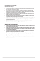
Outils et composants additionnels pour monter un ordinateur de bureau Processeur Intel® au format LGA2011-v3 Ventilateur du processeur compatible Intel® au format LGA2011-v3 Châssis d'ordinateur Disque(s) dur(s) SATA Tournevis Philips (cruciforme) Module(s) mémoire 1 sachet de vis Bloc d'alimentation Lecteur optique SATA (optionnel) Carte(s) graphique(s) Les outils et composants illustrés dans le tableau ci-dessus ne sont pas inclus avec la carte mère.
Chapitre 1 : Introduction au produit Introduction au produit 1.1 Vue d'ensemble de la carte mère 1.1.1 Avant de commencer 1 Suivez les précautions ci-dessous avant d'installer la carte mère ou d'en modifier les paramètres. Débranchez le câble d'alimentation de la prise murale avant de toucher les composants. • Utilisez un bracelet antistatique ou touchez un objet métallique relié au sol (comme l'alimentation) pour vous décharger de toute électricité statique avant de toucher aux composants.
1.1.2 Schéma de la carte mère Chapitre 1 Reportez-vous aux sections 1.1.9 Connecteurs internes et 2.3.1 Connecteurs arrières pour plus d'informations sur les connecteurs internes et externes.
Contenu du schéma Page 1-5 1-26 1-4 1-27 1-11 1-22 1-24 1-23 1-14 1-23 1-12 1-30 1-13 1-28 1-29 1-25 1-32 1-30 1-29 1-17 1-10 1-10 1-31 1-32 1-33 Chapitre 1 Connecteurs/Cavaliers/Boutons et interrupteurs/Ports 1. Slot DIMM DDR4 2. Connecteurs pour ventilateurs (4-pin CPU_FAN; 4-pin CPU_OPT; 4-pin W_PUMP; 4-pin H_AMP_FAN; 5-pin EXT_FAN; 4-pin CHA_FAN1-2) 3. Processeur au format LGA2011-v3 4. Connecteurs d'alimentation ATX (24-pin EATXPWR; 8-pin EATX12V_1; 4-pin EATX12V_2) 5. Bouton MemOK! 6.
1.1.3 Processeur La carte mère est livrée avec un socket LGA2011-v3 conçu pour l'installation d'un processeur Intel® Core™ i7. • Assurez-vous que tous les câbles sont débranchés lors de l'installation du processeur. • Lors de l'achat de la carte mère, vérifiez que le couvercle PnP est bien placé sur l'interface de connexion du processeur et que les broches de ce dernier ne sont pas pliées.
1.1.4 Mémoire système La carte mère est livrée avec huit (8) slots DIMM destinés à l'installation de modules mémoire DDR4 (Double Data Rate 4). Un module DDR4 s'encoche différemment d'un module DDR3 / DDR2 / DDR. NE PAS installer de module mémoire DDR3, DDR2 ou DDR sur les slots DIMM destinés aux modules DDR4. Installez au moins un des modules mémoire dans le slot A1*/B1*/C1*/D1*.
• Face(s) : SS - Simple face DS - Double face Support DIMM : Supporte un (1) module inséré dans les slots en configuration mémoire SingleChannel. Il est recommandé d'installer le module sur le slot D1* pour une meilleure compatibilité. Supporte deux (2) modules insérés dans une paire de slots en configuration mémoire Quad-Channel. Il est recommandé d'installer les modules sur les slots B1* et D1* pour une meilleure compatibilité.
Configurations mémoire Vous pouvez installer des modules mémoire DDR4 un-buffered et non ECC de 2 Go, 4 Go et 8 Go sur les interfaces de connexion DDR4. • Vous pouvez installer des modules mémoire de tailles variables dans le canal A, B, C et D. Le système se chargera de mapper la taille totale du canal de plus petite taille pour les configurations Quad-Channel (Quadri-Canal). Tout excédant de mémoire du canal le plus grand est alors mappé pour fonctionner en Single-Channel (Canal unique).
1.1.5 Slots d'extension Assurez-vous d'avoir bien débranché le câble d'alimentation avant d'ajouter ou de retirer des cartes d'extension. Manquer à cette précaution peut vous blesser et endommager les composants de la carte mère.
Processeur 40 lignes Mode de fonctionnement PCI Express 3.0 Configuration PCIEX16/X8_1 PCIEX16_2 PCIEX8_3 (recommandé pour une carte VGA) N/D N/D Deux cartes VGA/PCIe x16 x16 N/D Trois cartes x8 x16 x8 x16 Une carte VGA/PCIe Processeur 28 lignes Mode de fonctionnement PCI Express 3.
1.1.6 Boutons et interrupteurs embarqués Les boutons et les interrupteurs embarqués vous permettent de booster les performances lorsque vous travaillez à système ouvert. Idéal pour l'overclocking et les joueurs qui changent continuellement de configuration pour augmenter les performances du système. 1. Bouton de mise sous tension La carte mère intègre un bouton d'alimentation vous permettant d'allumer ou d'éteindre le système.
Bouton MemOK! L'installation de modules mémoire incompatibles avec la carte mère peut causer des erreurs d'amorçage du système. Lorsque cela arrive, le voyant DRAM_LED situé à côté de l'interrupteur MemOK! s'allume de manière continue. Maintenez le bouton MemOK! enfoncé jusqu'à ce que le voyant DRAM_LED clignote pour lancer le processus de mise au point automatique du problème de compatibilité mémoire et assurer un bon démarrage du système. • Consultez la section 1.1.
4. Interrupteur EZ XMP Utilisez cet interrupteur pour surcadencer les modules mémoire installés et ainsi profiter de performances mémoire accrues. Le voyant EZ XMP (XLED1) s'allume lorsque l'interrupteur EZ XMP est activé. Consultez la section 1.1.8 Témoins lumineux pour l'emplacement exact du voyant XLED1.
1.1.7 1. Cavaliers Cavalier Clear CMOS (2-pin CLRTC) Ce cavalier vous permet d'effacer la mémoire RTC (Real Time Clock) du CMOS. La mémoire CMOS stocke les éléments suivants : la date, l'heure et les paramètres du BIOS. La pile bouton intégrée alimente les données de la mémoire vive du CMOS, incluant les paramètres système tels que les mots de passe. Pour effacer la mémoire RTC : 1. Éteignez l'ordinateur, débranchez le cordon d'alimentation et retirez la pile de la carte mère. 2.
2. Cavalier de surtension du processeur (3-pin CPU_OV) Ce cavalier vous permet de régler une tension du processeur plus élevée de sorte à obtenir un overclocking plus flexible. Placez le capuchon de cavalier sur les broches 2-3 pour obtenir plus de réglages de tension, et sur les broches 1-2 pour restaurer les valeurs par défaut.
1.1.8 Témoins lumineux de la carte mère Témoins du POST Ces voyants vérifient les composants clés (CPU, DRAM, carte VGA ainsi que les périphériques de démarrage) en séquence au démarrage de la carte mère. Si une erreur est détectée, le voyant correspondant s'allume jusqu'à ce que le problème soit résolu. 2. Témoin EZ XMP (XLED1) Ce voyant s'allume lorsque vous activez l'interrupteur EZ XMP. Chapitre 1 1.
3. LED d'alimentation (PWR_LED) La carte mère est livrée avec une LED qui s'allume lorsque le système est sous tension, en veille ou en mode “soft-off”. Elle vous rappelle qu'il faut bien éteindre le système et débrancher le câble d'alimentation avant de connecter ou de déconnecter le moindre composant sur la carte mère. L'illustration ci-dessous indique l'emplacement de cette LED. 4.
Témoins Q-Code Ces voyants offrent un système d'affichage à code symbolisé par deux valeurs numériques pour vous informer de l'état du système. Consultez le tableau de débogage pour plus d'informations. Chapitre 1 5.
Tableau de débogage Q-Code Chapitre 1 Code Description 00 Non utilisé 01 Sous tension. Détection du type de réinitialisation (soft/hard).
Code Description 5A Erreur du processeur interne 5B Le PPI de réinitialisation n'est pas disponible 5C – 5F Réservé aux futurs codes d'erreur AMI E0 La reprise S3 est lancée (Le PPI de reprise S3 est appelé par le DXE IPL) E1 Exécution du Boot Script S3 E2 Reposter la vidéo E3 Appel de vecteur de réveil S3 du système d'exploitation E4 – E7 Réservé aux futurs codes de progression AMI E8 Échec de reprise S3 E9 PPI reprise S3 introuvable EA Erreur de script reprise démarrage S3 EB Erre
Tableau de débogage Q-Code Chapitre 1 Code Description 70 L'initialisation PCH DXE est lancée 71 L'initialisation PCH DXE SMM est lancée 72 Initialisation des périphériques PCH 73 – 77 Initialisation des périphériques PCH DXE (Module PCH spécifique) 78 Initialisation du module ACPI 79 Initialisation CSM 7A – 7F Réservé aux futurs codes AMI DXE 90 La phase de sélection de périphérique de démarrage Boot Device (BDS) est lancée 91 La connexion du pilote est lancée 92 L'initialisation du
Code Description A9 Démarrage de la configuration AA Réservé aux ASL (voir la section Codes d'état ASL ci-dessous) AB Configuration attente entrée AC Réservé aux ASL (voir la section Codes d'état ASL ci-dessous) AD Événement Prêt à démarrer AE Événement Legacy Boot (Démarrage hérité) AF Événement services de sortie de démarrage B0 Début de temps de définition d'adresse virtuelle MAP B1 Fin de temps de définition d'adresse virtuelle MAP B2 Initialisation des options Legacy de la ROM B3
1.1.9 Connecteurs internes 1. Connecteurs SATA 6.0 Gb/s Intel® X99 (7-pin SATA6G_12, SATA6G_34, SATA6G_56/SATAEXPRESS, SATA6G_78, SATA6G_910) Ces connecteurs sont destinés à des câbles Serial ATA pour la connexion de disques durs Serial ATA 6.0 Gb/s. L'installation de disques durs Serial ATA permet de créer des volumes RAID 0, 1, 5 et 10 par le biais de la technologie Intel® Rapid Storage. Extrémité à angle droit REMARQUE : Connectez l’extrémité à angle droit du câble SATA à votre lecteur SATA.
3. Interface M.2 (socket 3) Cette interface permet d'installer un module SSD M.2 (NGFF). • Cette interface n'est compatible qu'avec les périphériques de stockage de type M Key et 2242/2260/2280/22110. • Le connecteur M.2 partage la bande passante avec le connecteur U.2. Connecteur U.2 (U.2) Cette carte mère est livrée avec un connecteur U.2 qui prend en charge la norme de stockage PCIe 3.0 x4 NVM Express. Chapitre 1 2. Le connecteur U.2 partage la bande passante avec le connecteur M.2.
4. Connecteurs USB 3.0 (20-1 pin USB3_12, USB3_34) Ces connecteurs sont dédiés à la connexion de ports USB 3.0 supplémentaires. Ils sont conformes à la norme USB 3.0 qui peut supporter un débit allant jusqu'à 5 Gb/s. Si le panneau avant de votre châssis intègre un port USB 3.0, vous pouvez utiliser ce port pour brancher un périphérique USB 2.0. Le module USB 3.0 est vendu séparément. • Il est recommandé d'installer le pilote approprié pour profiter pleinement des ports USB 3.0 sous Windows® 7.
5. Connecteurs USB 2.0 (10-1 pin USB1112; USB1314) Ces connecteurs sont dédiés à des ports USB 2.0. Connectez le câble du module USB à l'un de ces connecteurs, puis installez le module dans un slot à l'arrière du châssis. Ces ports sont conformes à la norme USB 2.0 qui peut supporter un débit de 489 Mb/s. Ne connectez pas de câble 1394 aux ports USB pour éviter d'endommager la carte mère.
6. Connecteurs pour ventilateurs (4-pin CPU_FAN; 4-pin CPU_OPT; 4-pin W_PUMP; 4-pin H_AMP_FAN; 5-pin EXT_FAN; 4-pin CHA_FAN1-2) Connectez les câbles des ventilateurs à ces connecteurs sur la carte mère, en vous assurant que le fil noir de chaque câble corresponde à la broche de terre de chaque connecteur. Chapitre 1 • N'oubliez pas de connecter le câble du ventilateur du processeur au connecteur CPU_Fan de la carte mère.
7. Connecteurs d'alimentation ATX (24-pin EATXPWR; 8-pin EATX12V_1; 4-pin EATX12V_2) Ces connecteurs sont destinés aux prises d'alimentation ATX. Les prises d'alimentation sont conçues pour n'être insérées que dans un seul sens dans ces connecteurs. Trouvez le bon sens et appuyez fermement jusqu'à ce que la prise soit bien en place. Pour un système totalement configuré, nous vous recommandons d'utiliser une alimentation conforme aux caractéristiques ATX 12 V 2.
8. Connecteur panneau système (20-3 pin PANEL) Ce connecteur est compatible avec plusieurs fonctions intégrées au châssis. • LED d'alimentation système (PLED 2 broches ou 3-1 broches) Ce connecteur à 2 broches ou 3-1 broches est destiné à la LED d'alimentation système. Branchez le câble LED d'alimentation du châssis à ce connecteur. La LED d'alimentation système s'allume lorsque vous démarrez le système et clignote lorsque ce dernier est en veille.
9. Connecteur TPM (14-1 pin TPM) Ce connecteur est compatible avec le système Trusted Platform Module (TPM), permettant de stocker en toute sécurité les clés et certificats numériques, les mots de passe et les données. Un système TPM aide aussi à accroître la sécurité d'un réseau, protéger les identités numériques et garantir l'intégrité de la plate-forme. Le module TPM est vendu séparément.
11. Connecteur Thunderbolt (5-pin TB_HEADER) Ce connecteur est destiné à une carte Thunderbolt. Utilisez cette carte pour le transfert en natif des protocoles PCIe et DisplayPort entre un ordinateur et des appareils compatibles avec la technologie Thunderbolt™. La carte et les câbles Thunderbolt sont vendus séparément. 12.
13. Connecteur RGB (4-pin RGB_HEADER) Ce connecteur est dédié aux bandes LED RGB. • L'en-tête RGB prend en charge 5050 bandes de LED multicolores RGB (12V / G / R / B), avec une puissance nominale maximale de 2A (12V), et pas plus de 2 m. • Vérifiez que le câble d'extension LED RGB et la bande LED RGB sont connectés dans le bon sens, et que le connecteur +12V est aligné avec l'en-tête +12V de la carte mère.
14. 15. Connecteur d'extension ROG (18-1 pin ROG_EXT) Ce connecteur est dédié au panneau d'OC I/II, à la base avant, et autres périphériques ROG. • La base avant est vendue séparément. • Visitez le site internet www.asus.com pour plus d'informations sur le panneau OC et la base avant. Connecteur COM (10-1 pin COM) Ces connecteurs sont réservés à un port série (COM).
Connecteur pour port audio en façade (10-1 pin AAFP) Ce connecteur est dédié au module E/S audio disponible en façade de certains boîtiers d'ordinateurs et prend en charge les normes audio AC '97 et HD Audio. Branchez le câble du module E/S audio en façade à ce connecteur. • Nous vous recommandons de brancher un module HD Audio sur ce connecteur pour bénéficier d'un son de qualité HD.
Chapitre 1 1-34 Chapitre 1 : Introduction au produit
Chapitre 2 : Procédures d'installation de base 2 Procédures d'installation de base 2.1 Monter votre ordinateur 2.1.1 Installation de la carte mère Les illustrations de cette section sont uniquement données à titre indicatif. La typologie de la carte mère peut varier en fonction des modèles. Les étapes d'installation sont toutefois identiques. Placez la plaque d'E/S métallique ASUS sur l'ouverture dédiée à l'arrière de votre châssis d'ordinateur. 2.
3. Placez neuf (9) vis dans les pas de vis (marqués d'un cercle rouge sur l'illustration cidessous) pour sécuriser la carte mère au châssis. Chapitre 2 Ne vissez pas trop fort ! Vous risqueriez d'endommager la carte mère.
2.1.2 Installer le processeur Veuillez faire attention à l'ordre d'ouverture et de fermeture du double loquet. Suivez les instructions imprimées sur le scellé métallique de la trappe ou référez-vous aux illustrations ci-dessous. Le capuchon en plastique apparaîtra automatiquement une fois le processeur installé et la trappe correctement scellée.
A A B C B 2.1.3 Installer le ventilateur du processeur Si nécessaire, appliquez la pâte thermique sur la surface du processeur et du dissipateur avant toute installation.
Chapitre 2 Pour installer le ventilateur du processeur : ASUS STRIX X99 GAMING 2-5
2.1.4 Installer un module mémoire Installez au moins un des modules mémoire dans le slot A1*/B1*/C1*/D1*.
Connecteurs d'alimentation ATX OU ET • NE PAS connecter la prise 4 broches. Le faire peut entraîner une surchauffe de la carte mère dans des conditions d'utilisation intense. • Assurez-vous de connecter la prise 8 broches, ou de connecter les prises 4 et 8 broches simultanément. ASUS STRIX X99 GAMING Chapitre 2 2.1.
2.1.
2.1.7 Connecteur E/S avant Pour installer le kit ASUS Q-Connector Connecteur audio pour façade de châssis d'ordinateur AAFP Connecteur USB 2.0 Connecteur USB 3.0 USB 3.0 Chapitre 2 Connecteur USB 2.0 Les modules USB 2.0 et USB 3.0 sont vendus séparément.
2.1.
• Les illustrations de cette section ne sont fournies qu'à titre indicatif. La typologie de la carte mère peut varier en fonction des modèles. Les étapes d'installation sont toutefois identiques. • La CARTE D'EXTENSION POUR VENTILATEUR est vendue séparément.
2.1.9 Installer l'antenne Wi-Fi Installer l'antenne Wi-Fi à double bande ASUS 2T2R Connectez l'antenne Wi-Fi ASUS 2T2R fournie sur les ports Wi-Fi situés à l'arrière du châssis de votre ordinateur. IO Shield • Assurez-vous que l'antenne Wi-Fi ASUS 2T2R est bien installée sur les ports Wi-Fi situés à l'arrière du châssis de votre ordinateur. • Placez l'antenne à plus de 20 cm de toute personne. Les illustrations fournies ne sont données qu'à titre indicatif.
2.2 Bouton de mise à jour du BIOS USB BIOS Flashback USB BIOS Flashback est le moyen le plus efficace de mise à jour du BIOS ! Il permet aux passionnés d'overclocking de tester de nouvelles versions de BIOS en toute simplicité sans avoir à accéder au BIOS actuel ou au système d'exploitation. Connectez simplement un périphérique de stockage USB et maintenez le bouton dédié enfoncé pendant 3 secondes. Le BIOS est alors mis à jour sans qu'aucune autre manipulation ne soit requise.
2.3 Connecteurs arrières et audio de la carte mère 2.3.1 Connecteurs arrières Connecteurs arrières Chapitre 2 1. Bouton USB BIOS Flashback 7. Ports USB 3.0 E34 2. Port souris + clavier 8. Ports USB 3.0 (E2_5) : Le port inférieur est compatible avec la fonctionnalité USB BIOS Flashback) 3. Port réseau Intel* 9. Port USB 3.1 Type-C EC1 4. Port USB 3.1 Type-A EA2 10. Ports Wi-Fi 802.11 a/b/g/n/ac, Bluetooth V4.0* 5. Ports USB 2.0 78 11. Sortie S/PDIF optique 6. Ports USB 2.0 910 12.
• Le périphérique USB 3.0 connecté peut fonctionner en mode xHCI ou EHCI en fonction de la configuration du système d'exploitation. • Seuls les périphériques de stockage USB 3.0 sont pris en charge. • Il est fortement recommandé de connecter vos périphériques USB 3.0 sur les ports USB 3.0 pour un débit et des performances accrues. • Les périphériques USB 2.0 et 3.0 connectés peuvent fonctionner en mode xHCI ou EHCI en fonction de la configuration du système d'exploitation.
2.3.2 Connexions audio Connecteurs audio Connexion à un casque ou un microphone Connexion à des haut-parleurs stéréo Connexion à un système de haut-parleurs 2.
Connexion à un système de haut-parleurs 4.1 Connexion à un système de haut-parleurs 5.1 Chapitre 2 Sous Windows® 8.1 / 10, n'utilisez que la prise bleue claire pour les haut-parleurs latéraux en configuration multi-canale 6.
Connexion à un système de haut-parleurs 7.1 Assurez-vous d'avoir connecté le haut-parleur arrière au port bleu clair lorsque la fonctionnalité DTS UltraPC II est activée. 2.4 1. 2. 3. 4. 5. 6. Chapitre 2 2-18 Démarrer pour la première fois Après avoir effectué tous les branchements, refermez le châssis d'ordinateur. Assurez-vous que tous les interrupteurs sont éteints. Connectez le câble d'alimentation au connecteur d'alimentation à l'arrière du châssis.
Bip BIOS Description 1 bip court Processeur graphique détecté Démarrage rapide désactivé Aucun clavier détecté 1 bip continu suivi de 2 bips courts suivis d'une pause (répété) Aucune mémoire détectée 1 bip continu suivi de 3 bips courts Processeur graphique non détecté 1 bip continu suivi de 4 bips courts Panne d'un composant matériel 7. 2.5 Au démarrage, maintenez la touche enfoncée pour accéder au menu de configuration du BIOS.
Chapitre 2 2-20 Chapitre 2 : Procédures d'installation de base
Chapitre 3 : Le BIOS Le BIOS 3.1 Présentation du BIOS 3 Le tout nouveau BIOS UEFI (Extensible Firmware Interface) d'ASUS est conforme à l'architecture UEFI et offre une interface conviviale allant au-delà de la simple saisie traditionnelle au clavier grâce à la possibilité de configuration du BIOS à la souris. Vous pouvez maintenant naviguer dans le BIOS UEFI avec la même fluidité que sous un système d'exploitation. Le terme «BIOS» spécifié dans ce manuel se réfère au “BIOS UEFI” sauf mention spéciale.
3.2 Programme de configuration du BIOS Utilisez le programme de configuration du BIOS pour mettre à jour ou modifier les options de configuration du BIOS. L'écran du BIOS comprend la touche Pilote et une aide en ligne pour vous guider lors de l'utilisation du programme de configuration du BIOS. Accéder au BIOS au démarrage du système Pour accéder au BIOS au démarrage du système, appuyez sur lors du POST (Power-On Self Test). Si vous n'appuyez pas sur , le POST continue ses tests.
3.2.1 EZ Mode Par défaut, l'écran EZ Mode est le premier à apparaître lors de l'accès au BIOS. L'interface EZ Mode offre une vue d'ensemble des informations de base du système, mais permet aussi de modifier la langue du BIOS, le mode de performance et l'ordre de démarrage des périphériques. Pour accéder à l'interface Advanced Mode, sélectionnez Advanced Mode ou appuyez sur la touche F7 de votre clavier. Le type d'interface par défaut du BIOS peut être modifié. Reportez-vous à la section 3.
3.2.2 Advanced Mode (Mode avancé) L'interface Advanced Mode (Mode avancé) offre des options avancées pour les utilisateurs expérimentés dans la configuration des paramètres du BIOS. L'écran ci-dessous est un exemple de l'interface Advanced Mode. Consultez les sections suivantes pour plus de détails sur les diverses options de configuration. Pour accéder à l'interface avancée, cliquez sur Exit (Sortie), puis sélectionnez Advanced Mode ou appuyez sur la touche F7 de votre clavier.
Barre de menus La barre de menus située en haut de l'écran affiche les éléments suivants : My Favorites (Favoris) Accès rapide aux éléments de configuration les plus utilisés Main (Principal) Modification des paramètres de base du système Ai Tweaker Modification des paramètres d'overclocking du système Advanced (Avancé) Modification des paramètres avancés du système Monitor (Surveillance) Affiche la température et l'état des différentes tensions du système et permet de modifier les paramètres de ve
Note rapide (F9) Ce bouton vous permet de prendre des notes dans le BIOS. • Cette fonctionnalité ne prend pas en charge les touches ou les raccourcis clavier suivants : touche Suppr. et raccourcis copier, couper et coller. • Seuls les caractères alphanumériques peuvent être utilisés pour la saisie de notes. Raccourcis Le bouton situé au-dessus de la barre de menu contient les touches de navigation de l'interface de configuration du BIOS.
3.2.3 Contrôle Q-Fan La fonctionnalité Q-Fan vous permet de sélectionner un profil de ventilateur pour une utilisation spécifique ou configurer manuellement la vitesse de rotation des ventilateurs installés.
Configuration manuelle des ventilateurs Sélectionnez le mode Manuel de la liste des profils pour configurer manuellement la vitesse de rotation des ventilateurs. Points de vitesse Configuration manuelle des ventilateurs Pour configurer vos ventilateurs manuellement : 1. Sélectionnez un ventilateur. 2. Faites glisser les points de vitesse pour modifier la vitesse de rotation du ventilateur. 3. Cliquez sur Appliquer pour enregistrer les modifications et cliquez sur Exit (ESC) (Sortie) pour quitter.
3.2.4 Assistant EZ Tuning L'assistant EZ Tuning vous permet d'optimiser la fréquence du processeur et de la mémoire ainsi que la vitesse du ventilateur du processeur. Vous pouvez également créer des volumes RAID par le biais de cet assistant. Configuration OC Configuration RAID OC Tuning Pour démarrer OC Tuning : 1. pour Chapitre 3 2. 3. Appuyez sur la touche de votre clavier ou cliquez sur accéder à l'écran de l'assistant EZ Tuning, puis cliquez sur Suivant.
4. Sélectionnez un système de refroidissement principal refroidisseur boîtier, refroidisseur tour, refroidisseur à eau ou Je ne suis pas sûr, puis cliquez sur Suivant. 5. Après avoir sélectionné le système de refroidissement principal, cliquez sur Suivant puis cliquez sur Oui pour démarrer OC Tuning. Création d'un volume RAID Pour créer un volume RAID : 1. 2. 3. Appuyez sur la touche de votre clavier ou cliquez sur accéder à l'écran de l'assistant EZ Tuning, puis cliquez sur Suivant.
4. Sélectionnez le type de stockage RAID, soit Easy Backup ou Super Speed, puis cliquez sur Suivant. a. Pour Easy Backup, cliquez sur Suivant, puis sélectionnez Easy Backup (RAID1) ou Easy Backup (RAID10). Pour quatre disques durs, seule l'option Easy Backup (RAID 10) est disponible. 5. 6. Pour Super Speed, cliquez sur Suivant, puis sélectionnez Super Speed (RAID 0) ou Super Speed (RAID 5). Chapitre 3 b.
3.3 My Favorites (Favoris) My Favorites est un espace personnel à partir duquel vous pouvez aisément accéder à et modifier vos éléments de configuration de BIOS favoris. My Favorites (Mes favoris) comprend plusieurs éléments par défaut liés aux performances, à l'économie d'énergie et au démarrage rapide. Vous pouvez personnaliser cet écran en ajoutant ou en supprimant des éléments.
Ajouter des éléments à la liste des favoris Pour ajouter un élément fréquemment utilisé à la liste des favoris : 1. 2. Appuyez sur la touche de votre clavier ou cliquez sur accéder à la liste des menus du BIOS. Sélectionnez le(s) élément(s) de BIOS à ajouter à la liste de vos favoris. pour Menus principaux Éléments à ajouter à la liste des favoris Sous-menus Supprime tous les favoris Restaure les favoris par défaut 3.
3.4 Menu Main (Principal) L'écran du menu principal apparaît lors de l'utilisation de l'interface Advanced Mode du BIOS. Ce menu offre une vue d'ensemble des informations de base du système et permet de régler la date, l'heure, la langue et les paramètres de sécurité du système. Security (Sécurité) Ce menu permet de modifier les paramètres de sécurité du système. Chapitre 3 3-14 • Si vous avez oublié le mot de passe d'accès au BIOS, vous pouvez le réinitialiser en effaçant la mémoire CMOS.
3.5 Menu Ai Tweaker Le menu Ai Tweaker permet de configurer les éléments liés à l'overclocking. Prenez garde lors de la modification des éléments du menu Ai Tweaker. Une valeur incorrecte peut entraîner un dysfonctionnement du système. Les options de configuration de cette section varient en fonction du type de processeur et de modules mémoire installés sur la carte mère. Faites défiler la page pour afficher plus d'éléments.
Cet élément n'apparaît que si vous réglez CPU Strap sur [100MHz], [125MHz], [167MHz], ou [250MHz]. Source Clock Tuner [Auto] Cet élément vous permet de sélectionner l'horloge source de la bande du processeur pour une meilleure capacité d'overclocking. Options de configuration : [Auto] [8Ohm dbl] [7Ohm dbl] [6Ohm dbl] [5Ohm dbl] [4Ohm dbl] [3Ohm dbl] [2Ohm dbl] PLL Selection (Sélection PLL) [Auto] Cet élément est par défaut réglé sur LC PLL pour améliorer la stabilité.
BCLK Frequency: DRAM Frequency Ratio (Ratio fréquence de base / fréquence DRAM) [Auto] Ajuste la fréquence de base du ratio de fréquence de la mémoire DRAM. [Auto] Le ratio fréquence de base / fréquence DRAM est optimisé. [100:100] Le ratio fréquence de base / fréquence DRAM est défini sur 100:100. [100:133] Le ratio fréquence de base / fréquence DRAM est défini sur 100:133. DRAM Frequency (Fréquence mémoire DRAM) [Auto] Permet de définir la fréquence de fonctionnement de la mémoire.
External DIGI+ Power Control (Gestion d'alimentation DIGI+ externe) CPU Input Boot Voltage (Tension d'entrée démarrage processeur) [Auto] Permet de définir une valeur de tension d'entrée au démarrage du processeur plus élevée pour améliorer les capacités d'overclocking. Utilisez les touches <+> et <-> de votre clavier pour ajuster la valeur. La fourchette de valeurs est comprise entre 0.80V et 2.7V par incréments de 0.01V.
3.6 Menu Advanced (Avancé) Le menu Advanced permet de modifier certains paramètres du processeur et d'autres composants du système. Chapitre 3 Prenez garde lors de la modification des paramètres du menu Advanced. Une valeur incorrecte peut entraîner un dysfonctionnement du système.
3.6.1 CPU Configuration (Configuration du processeur) Les éléments de ce menu affichent les informations du processeur automatiquement détectées par le BIOS. Les éléments apparaissant sur cet écran peuvent varier selon le type de processeur installé. Hyper-Threading [ALL] [Enabled] La technologie Intel® Hyper-Threading permet à un processeur d'être détecté comme deux processeurs logiques sous le système d'exploitation, autorisant ce dernier à exécuter deux threads simultanément.
3.6.2 PCH Configuration (Configuration PCH) PCI Express Configuration (Configuration PCI Express) Chapitre 3 Configure certains paramètres des slots PCI Express. PCIEX4_1 Speed [Auto] Configure la valeur de la vitesse du slot PCIEX4_1. Options de configuration : [Auto] [Gen1] [Gen2] PCIEX1_2 Speed [Auto] Configure la valeur de la vitesse du slot PCIEX1_2.
3.6.3 PCH Storage Configuration (Configuration de stockage de la puce PCH) Lors de l'accès au BIOS, celui-ci détecte automatiquement la présence des périphériques SATA. Ces éléments affichent Not Installed si aucun lecteur SATA n'est installé dans le système. Faites défiler l'écran vers le bas pour afficher d'autres éléments du BIOS. SATA Controller 1 Mode Selection (Sélection de mode de contrôleur 1 SATA) [AHCI] Chapitre 3 Détermine le mode de configuration SATA.
SATA6G_1(Gris) - SATA6G_6(Gris) SATA6G_1(Gris) - SATA6G_6(Gris) [Enabled] Cet élément permet d'activer ou désactiver les connecteurs SATA de manière individuelle. Options de configuration : [Disabled] [Enabled] Hot Plug (Branchement à chaud) [Disabled] Cet élément permet de configurer un port SATA comme Hot Plug. Options de configuration : [Disabled] [Enabled] SATA Controller 2 Mode Selection (Sélection de mode de contrôleur 2 SATA) [AHCI] Détermine le mode de configuration SATA.
3.6.4 System Agent Configuration (Agent de configuration système) Configuration PCI-E du NorthBridge Les éléments de ce menu permettent de configurer la vitesse de fonctionnement du slot PCIEX16_1. 3.6.5 USB Configuration (Configuration USB) Les éléments de ce menu vous permettent de modifier les fonctions liées à l'interface USB. Chapitre 3 L'élément Mass Storage Devices affiche les valeurs auto-détectées. Si aucun périphérique USB n'est détecté, l'élément affiche None.
3.6.6 Platform Misc Configuration (Paramètres de plateforme) Les éléments de ce menu permettent de configurer les fonctionnalités liées à la plateforme. 3.6.7 Onboard Devices Configuration (Configuration des périphériques embarqués) Chapitre 3 Faites défiler l'écran vers le bas pour afficher les autres éléments du BIOS.
HD Audio Controller (Contrôleur audio HD) [Enabled] [Enabled] [Disabled] Active le contrôleur haute définition audio. Désactive le contrôleur. PCIEX4_1 Slot Bandwidth (Bande passante du slot PCIEX4_1) [Auto] [Auto] [X1 Mode] [X4 Mode] Fonctionne en mode AUTO avec les ports USB3.1_EC1, USB3.1_EA2 et le slot PCIEX1_2 activés. Fonctionne en mode x1 avec le port USB3.1_EC1_EA2 et le slot PCIEX1_2 activés. Fonctionne en mode x4 avec les ports USB3.
RGB LED lighting effects (Effets lumineux LED RGB) [Default] Permet de régler les effets lumineux des LED RGB. Options de configuration : [Default] [Auto] [Static] [Breathing] [Strobing] [Color Cycle] L'élément suivant n'apparaît que si vous réglez cette option sur [Static], [Breathing], ou [Strobing]. RGB LED lighting color (Couleur d'éclairage LED RGB) Permet de régler les couleurs d'éclairage des LED RGB.
3.6.8 APM Configuration (Gestion d'alimentation avancée) ErP Ready [Disabled] Permet au BIOS de couper l'alimentation de certains composants lorsque l'ordinateur est en mode veille S4/S5 pour satisfaire aux normes ErP. Sur [Enabled], toutes les autres options PME seront désactivées. Options de configuration : [Disabled] [Enabled(S4+S5)] [Enabled(S5)] 3.6.9 Network Stack Configuration (Configuration de pile réseau) Network stack (Pile réseau) [Disabled] Active ou désactive la pile réseau du BIOS UEFI.
3.6.10 HDD/SSD SMART Configuration (Configuration SMART disque dur/SSD) Ce menu affiche les informations SMART des périphériques connectés. 3.6.11 NVMe Configuration (Configuration NVMe) Chapitre 3 Ce menu affiche les informations du contrôleur NVMe et des lecteurs des périphériques connectés.
3.7 Menu Monitor (Surveillance) Le menu Monitor affiche l'état de la température et de l'alimentation du système, mais permet aussi de modifier les paramètres de ventilation. Faites défiler l'écran vers le bas pour afficher d'autres éléments du BIOS. CPU Q-Fan Control (Contrôle Q-Fan du processeur) [Auto] [Auto] [PWM Mode] DC Mode] [Disabled] Détecte le type de ventilateur branché et bascule vers le mode de fonctionnement approprié. Utilisez ce mode si vous avez installé un ventilateur PWM à 4 broches.
Water Pump Control (Contrôle de la pompe à eau) [Disabled] Permet de régler le contrôle de la pompe à eau. Options de configuration : [Disabled] [Auto] [DC Mode] [PWM Mode] HAMP Fan Control (Contrôle du ventilateur HAMP) [Auto] Permet de régler le contrôle du ventilateur HAMP.
3.8 Menu Boot (Démarrage) Le menu Boot vous permet de modifier les options de démarrage du système. Fast Boot (Démarrage rapide) [Enabled] [Disabled] [Enabled] Permet de revenir à une vitesse de démarrage standard du système. Active la fonctionnalité de démarrage rapide du système. Redirection Support (Prise en charge de la redirection) [Disabled] Si l’option [Disabled] est sélectionnée, la fonction de prise en charge de la redirection est désactivée.
Setup Mode (Interface par défaut) [EZ Mode] [ Advanced Mode] [EZ Mode] Utiliser le mode avancé comme interface BIOS par défaut. Utiliser le mode EZ Mode comme interface BIOS par défaut. CSM (Compatibility Support Module) Configure les paramètres de démarrage CSM pour une meilleure prise en charge de divers périphériques VGA, de démarrage et autres composants externes.
Secure Boot (Démarrage sécurisé) Configure les paramètres Windows® Secure Boot et gère ses clés pour protéger le système contre les accès non autorisés et les logiciels malveillants lors de l'exécution du POST. OS Type (Type de système d'exploitation) [Windows UEFI mode] [Windows UEFI mode] Exécute Microsoft® Secure Boot. N'utilisez cette option que si vous utilisez un système d'exploitation Windows® compatible UEFI ou prenant en charge la fonction Microsoft® Secure Boot.
3.9 Menu Tool (Outils) Le menu Tool vous permet de configurer les options de fonctions spéciales. Sélectionnez un élément, puis appuyez sur pour afficher le sous-menu. GPU Post (Informations Post GPU) Cet élément affiche les cartes graphiques installées sur votre carte mère. Il affiche également le nombre recommandé de cartes graphiques à installer sur la carte mère pour optimiser les performances. 3.9.1 ASUS EZ Flash 3 Utility Permet d'activer la fonction ASUS EZ Flash 3.
3.9.2 Secure Erase La vitesse de lecture/écriture d'un lecteur SSD peut se dégrader au fil du temps comme tout support de stockage en raison du traitement des données. Secure Erase permet de nettoyer totalement et en toute sécurité votre SSD pour le restaurer dans un état de performance comparable à sa sortie d'usine. Secure Erase est uniquement disponible en mode AHCI. Veillez à régler le mode de fonctionnement SATA sur AHCI.
Setup Animator (Animateur de configuration) [Disabled] Cet élément vous permet d'activer ou de désactiver l'animateur de configuration. Options de configuration : [Enabled] [Disabled] 3.9.3 ASUS Overclocking Profile (Profil d'overclocking ASUS) Le profil d'overclocking ASUS vous permet de stocker ou de restaurer différents profils de configuration du BIOS.
3.9.4 ASUS SPD Information (Informations SPD ASUS) Cet élément permet d'afficher les informations de SPD des modules mémoire installés.
3.10 Menu Exit (Sortie) Le menu Exit vous permet non seulement de charger les valeurs optimales ou par défaut des éléments du BIOS, mais aussi d'enregistrer ou d'annuler les modifications apportées au BIOS. Il est également possible d'accéder à l'interface EZ Mode à partir de ce menu. Load Optimized Defaults (Charger les paramètres optimisés par défaut) Cette option vous permet de charger les valeurs par défaut de chaque paramètre des menus du BIOS.
3.11 Mettre à jour le BIOS Le site Web d'ASUS contient les dernières versions de BIOS permettant d'améliorer la stabilité, la compatibilité ou les performances du système. Toutefois, la mise à jour du BIOS est potentiellement risquée. Si votre version de BIOS actuelle ne pose pas de problèmes, NE TENTEZ PAS de mettre à jour le BIOS manuellement. Une mise à jour inappropriée peut entraîner des erreurs de démarrage du système.
3. 4. 5. Chapitre 3 6. Appuyez sur la touche de votre clavier pour sélectionner le champ Drive (Lecteur). Utilisez les touches Haut/Bas du clavier pour sélectionner le support de stockage contenant le fichier BIOS, puis appuyez sur . Appuyez de nouveau sur pour sélectionner le champ Folder Info (Infos de dossier). Utilisez les touches Haut/Bas du clavier pour localiser le fichier BIOS, puis appuyez sur pour lancer le processus de mise à jour du BIOS.
• Cette fonction est compatible avec les périphériques de stockage Flash au format FAT 32/16 et n'utilisant qu'une seule partition. • NE PAS éteindre ou redémarrer le système lors de la mise à jour du BIOS ! Le faire peut causer un échec d'amorçage du système ! Assurez-vous de charger les paramètres par défaut du BIOS pour garantir la stabilité et la compatibilité du système. Pour ce faire, sélectionnez l'option Load Optimized Defaults du menu Exit. Consultez la section 3.
3.11.3 Utilitaire ASUS CrashFree BIOS 3 ASUS CrashFree BIOS 3 est un outil de récupération automatique qui permet de restaurer le BIOS lorsqu'il est défectueux ou corrompu suite à une mise à jour. Vous pouvez mettre à jour un BIOS corrompu en utilisant le DVD de support de la carte mère ou un périphérique de stockage amovible contenant le fichier BIOS à jour. Le fichier BIOS contenu sur le DVD de support de la carte mère peut être plus ancien que celui publié sur le site Web d'ASUS (www.asus.com).
Chapitre 3 3-44 Chapitre 3 : Le BIOS
Chapitre 4 : Configurations RAID Configurations RAID 4.1 Configuration de volumes RAID 4 Cette carte mère prend en charge la solution RAID suivante : Intel® Rapid Storage Technology : RAID 0, RAID 1, RAID 10 et RAID 5. Si vous souhaitez installer un système d'exploitation sur un disque dur faisant partie d'un volume RAID, vous devez créer un disque du pilote RAID et charger le pilote lors de l'installation du système d'exploitation. Référez-vous à la section 4.
4.1.2 Installer des disques durs Serial ATA (SATA) 4.1.3 Utilitaire Intel® Rapid Storage Technology du BIOS UEFI Cette carte mère permet l'installation de disques durs SATA. Pour de meilleures performances, installez des disques durs identiques de même capacité et modèle. Pour installer des disques durs SATA destinés à une configuration RAID : 1. Installez les disques SATA dans les baies de votre châssis d'ordinateur dédiées aux disques durs. 2. Connectez les câbles de signal SATA. 3.
Créer un volume RAID Pour créer un volume RAID : 1. À partir du menu de la technologie Intel® Rapid Storage, sélectionnez Create RAID Volume, puis appuyez sur . L'écran ci-dessous apparaît : 2. 3. Chapitre 4 4. Quand le champ de nom est surligné, saisissez le nom désiré du volume RAID, puis appuyez sur . Quand l'élément RAID Level est surligné, appuyez sur pour sélectionner un type de configuration RAID, puis appuyez à nouveau sur .
5. Quand l'élément Strip Size est sélectionné, appuyez sur pour sélectionner la taille des segments de l'ensemble RAID (RAID 0, 10 et 5 uniquement), puis appuyez à nouveau sur . Les valeurs s'échelonnent entre 4 Ko et 128 Ko. La taille par défaut est 128 Ko. Valeurs standards : RAID 0 : 128Ko RAID 10 : 64Ko RAID 5 : 64Ko Pour les serveurs, il est recommandé d'utiliser une taille de segment plus faible.
Supprimer un volume RAID Vous ne pourrez pas restaurer les données après avoir supprimé un volume RAID. Assurezvous d'avoir sauvegardé vos données importantes avant de supprimer un volume RAID. Pour supprimer un volume RAID : 1. À partir du menu de la technologie Intel® Rapid Storage, sélectionnez le volume RAID que vous souhaitez supprimer, puis appuyez sur .
4.1.4 Utilitaire Intel® Rapid Storage Technology Option ROM Pour accéder à l'utilitaire Intel® Rapid Storage Technology Option ROM : 1. Démarrez le système. 2. Au POST, appuyez sur pour afficher le menu principal de l'utilitaire. RAID Volumes: None defined. Physical Devices: Port Device Model 0 ST3160812AS 1 ST3160812AS 2 ST3160812AS 3 ST3160812AS Serial # 9LS0HJA4 9LS0F4HL 3LS0JYL8 9LS0BJ5H Size 149.0GB 149.0GB 149.0GB 149.
Créer un volume RAID Pour créer un volume RAID : 1. Dans le menu principal de l'utilitaire, sélectionnez 1. CREATE VOLUME, puis appuyez sur . L'écran ci-dessous apparaît : Name: Volume 0 RAID Level: aaaaaaaaaaaaaaa Disks: dssdsdsds Strip Size:aaaaaaaaaaaaaaaa Capacity:aaaaaaaaaaaaaa Sync:aaaaaaaaaa Create volume [HELP] Enter a unique volume name that has no special characters and is 16 characters or less. 2. 3. 4. Spécifiez un nom pour le volume RAID puis appuyez sur .
5. 6. Utilisez les flèches haut/bas pour mettre un disque en surbrillance, puis appuyez sur pour le sélectionner. Un petit triangle distinguera ce disque. Appuyez sur pour terminer votre sélection. Utilisez les flèches haut/bas pour sélectionner la taille des segments de l'ensemble RAID (RAID 0, 10 et 5 uniquement), puis appuyez sur . Les valeurs s'échelonnent entre 4 Ko et 128 Ko. La taille par défaut est 128 Ko.
Supprimer un volume RAID Vous ne pourrez pas restaurer les données après avoir supprimé un volume RAID. Assurezvous d'avoir sauvegardé vos données importantes avant de supprimer un volume RAID. Pour supprimer un volume RAID : 1. À partir du menu principal de l'utilitaire, sélectionnez 2. Delete RAID Volume et appuyez sur . L'écran ci-dessous apparaît : Name Volume0 [DELETE VOLUME MENU] Level Drives RAID0 (Stripe) 2 Capacity 298.
Quitter l'utilitaire Intel® Rapid Storage Technology Option ROM Pour quitter l'utilitaire : 1. Dans le menu principal de l'utilitaire, sélectionnez 6. Exit, et appuyez sur . Le message d'avertissement suivant apparaît : [CONFIRM EXIT] Are you sure you want to exit? (Y/N): 2. Appuyez sur pour quitter l'utilitaire ou sur pour revenir au menu principal. 4.2 Créer un disque du pilote RAID 4.2.1 Créer un disque du pilote RAID sous Windows® Pour installer le pilote RAID sous Windows® : 1.
Appendice Appendice Notices Rapport de la Commission Fédérale des Communications (FCC) Cet appareil est conforme à l'alinéa 15 des règles établies par la FCC. Son utilisation est sujette aux deux conditions suivantes : • Cet appareil ne doit pas créer d'interférences nuisibles, et. • Cet appareil doit tolérer tout type d'interférences, y compris celles susceptibles de provoquer un fonctionnement non souhaité de l'appareil.
Déclaration de conformité d'Industrie Canada Cet appareil numérique de la Classe B est conforme à la norme NMB-003 du Canada. Cet appareil numérique de la Classe B respecte toutes les exigences du Règlement sur le matériel brouilleur du Canada. Le présent appareil est conforme aux standards CNR d'Industrie Canada applicables aux appareils radio exempts de licence.
REACH En accord avec le cadre réglementaire REACH (Enregistrement, Evaluation, Autorisation, et Restriction des produits chimiques), nous publions la liste des substances chimiques contenues dans nos produits sur le site ASUS REACH : http://csr.asus.com/english/REACH. htm. NE PAS jeter ce produit avec les déchets ménagers. Ce produit a été conçu pour permettre une réutilisation et un recyclage appropriés des pièces.
Conformité aux directives de la FCC du module sans fil Bluetooth L'antenne utilisée par cet émetteur ne doit pas être située près de ou utilisée conjointement avec d'autres antennes ou émetteurs. Déclaration d'Industrie Canada relative aux modules sans fil Bluetooth Cet appareil numérique de la Classe B respecte toutes les exigences du Règlement sur le matériel brouilleur du Canada. Déclaration du bureau BSMI (Taiwan) relative aux appareils sans fil Termes de licence Google™ Copyright© 2016 Google Inc.
ASUS STRIX X99 GAMING Lietuvių ASUSTeK Computer Inc. ar šo paziņo, ka šī ierīce atbilst Direktīvas 1999/5/EK būtiskajām prasībām un citiem citiem saistošajiem nosacījumiem. Pilns ES atbilstības paziņojuma teksts pieejams šeit: www.asus.com/support Šį įrenginį galima naudoti toliau išvardytose šalyse: Norsk ASUSTeK Computer Inc. erklærer herved at denne enheten er i samsvar med hovedsaklige krav og andre relevante forskrifter i direktivet 1999/5/EF.
Informations de contact ASUS ASUSTeK COMPUTER INC. Adresse Téléphone Fax Site Web Support technique Téléphone Fax Support en ligne 4F, No. 150, Li-Te Rd., Peitou, Taipei 112, Taiwan +886-2-2894-3447 +886-2-2890-7798 www.asus.com +86-21-38429911 +86-21-5866-8722, ext. 9101# http://qr.asus.com/techserv ASUS COMPUTER INTERNATIONAL (Amérique) Adresse 800 Corporate Way, Fremont, CA 94539, USA Téléphone +1-510-739-3777 Fax +1-510-608-4555 Site Web http://www.asus.
DECLARATION OF CONFORMITY Per FCC Part 2 Section 2. 1077(a) Asus Computer International Responsible Party Name: 800 Corporate Way, Fremont, CA 94539. Address: Phone/Fax No: (510)739-3777/(510)608-4555 hereby declares that the product Product Name : Motherboard Model Number : STRIX X99 GAMING Conforms to the following specifications: FCC Part 15, Subpart B, Unintentional Radiators Supplementary Information: This device complies with part 15 of the FCC Rules.
Appendice A-8 Appendice