A7N266-VM User Guide Motherboard ®
Checklist Product Name: Manual Revision: Release Date: A7N266-VM 1.00 E1014 March 2002 Copyright © 2002 ASUSTeK COMPUTER INC. All Rights Reserved. No part of this manual, including the products and software described in it, may be reproduced, transmitted, transcribed, stored in a retrieval system, or translated into any language in any form or by any means, except documentation kept by the purchaser for backup purposes, without the express written permission of ASUSTeK COMPUTER INC. (“ASUS”).
About this guide Features This user manual contains complete information for installing the ASUS A7N266-VM motherboard. How this guide is organized • • • • • • • Chapter 1: Product introduction. A summary of product features and special attributes of new technologies. Chapter 2: Hardware information. A list of hardware setup procedures and descriptions of all jumpers and connectors on the motherboard. Chapter 3: Powering up. Describes the power up sequence with information on BIOS beep codes.
Contents Safeguards About this guide .......................................................................................... iii How this guide is organized ............................................................... iii Conventions used in this guide .......................................................... iii Safety information ...................................................................................... vi FCC/CDC statements .............................................................
Contents 4.1.1 4.1.2 Upon First Use of the Computer System ........................... 35 Updating BIOS Procedures ............................................... 37 4.2 BIOS Setup Program ...................................................................... 39 4.2.1 BIOS Menu Bar ................................................................. 40 4.2.2 Legend Bar ........................................................................ 40 4.3 Main Menu ................................................
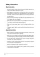
Safety information Electrical safety • To prevent electrical shock hazard, disconnect the power cable from the electrical outlet before relocating the system. • When adding or removing devices to or from the system, ensure that the power cables for the devices are unplugged before the signal cables are connected. Disconnect all power cables from the existing system before you add a device. • Before connecting or removing signal cables from the motherboard, ensure that all power cables are unplugged.
FCC/CDC statements Federal Communications Commission Statement This device complies with FCC Rules Part 15. Operation is subject to the following two conditions: • • This device may not cause harmful interference, and This device must accept any interference received including interference that may cause undesired operation. This equipment has been tested and found to comply with the limits for a Class B digital device, pursuant to Part 15 of the FCC Rules.
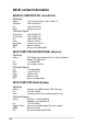
ASUS contact information ASUSTeK COMPUTER INC. (Asia-Pacific) Marketing Address: Telephone: Fax: Email: 150 Li-Te Road, Peitou, Taipei, Taiwan 112 +886-2-2894-3447 +886-2-2894-3449 info@asus.com.tw Technical Support Tel (English): Tel (Chinese): Fax: Email: Newsgroup: WWW: FTP: +886-2-2890-7123 +886-2-2890-7113 +886-2-2890-7698 tsd@asus.com.tw cscnews.asus.com.tw www.asus.com.tw ftp.asus.com.
Chapter 1 Product introduction
ASUS A7N266-VM motherboard
Welcome! Thank you for buying the ASUS® A7N266-VM motherboard! The A7N266-VM is powered by AMD® Athlon™, Athlon™ XP and Duron™ processors and supplies advanced features to ensure long-lasting, superlative performance. The ASUS® A7N266-VM motherboard is the prime choice for home PCs and workstations.
1.2 Core Specifications The A7N266-VM motherboard is designed and assembled according to the highest standards. This ASUS motherboard represents the latest advances and offers users the finest componentry available today... AMD® Athlon™/ Athlon™ XP and Duron™ Socket A (462) Processor North Bridge Chipset: the nVidia® 220D GeForce MX Integrated GPU/ North Bridge controller chipset. The controller supports a 64bit DDR memory controller and up to 1 GB of 266/200MHz DDR SDRAM memory.
Expansion: One AGP 4X, four USB ports, three PCI slots, S/PDIF digital audio connector, front audio panel connector, infrared port. 1.3 Special Features Temperature, Fan and Voltage Monitoring: CPU temperature is monitored by ASUS ASIC through a thermal sensor mounted under the CPU. The sensor signals the computer to prevent overheating and damage. The CPU and system fans can be monitored for RPM and failure. System voltage levels are monitored to ensure stable current to critical motherboard components.
1.4 Motherboard Components Before installing the A7N266-VM motherboard, take time to familiarize yourself with its configuration: understanding the motherboard makes upgrading easy. Sufficient knowledge of specifications prevents accidental damage. Processor Support Chipsets Main Memory Expansion Slots System I/O Hardware Monitoring Special Feature Audio Features Power Form Factor Location Socket A for AMD Athlon and Duron Processors ....... 1 nVidia® 220D North Bridge ................................
1.4.
Chapter 2 Hardware information
ASUS A7N266-VM motherboard
2.1 Motherboard installation The A7N266-VM uses the Micro-ATX form factor, measuring 24.5 cm (9.6 in.) x 24.5 cm (9.6 in.) - a standard fit for most large chassis. WARNING! Unplug the power cord before installing the motherboard. Failure to do so may cause you physical injury and damage motherboard components. 2.1.1 Placement direction When installing the motherboard, take care to orient the chassis correctly: The edge with external ports goes to the rear part of the chassis. Refer to the image below.
24.5cm (9.64in) PS/2 T: Mouse B: Keyboard Bottom: USBPWR01 KBPWR1 A7N266-VM Socket 462 Top: Line In Mic In 0 1 2 3 CD_IN1 AUDIO_COM1 Accelerated Graphics Port (AGP) nVidia PCI 1 Audio Codec Secondary IDE ® BSEL0 BSEL1 ASUS ASIC PCI 2 with Hardware Monitor PCI 3 Super I/O COM2 Primary IDE MCP-D Chipset AAPANEL1 30.5cm (12.
2.2 Layout contents CPU, Memory and Expansion Slots 1) Socket 462 p. 12 CPU Support 2) DIMM 1/2 p. 14 System Memory Support 3) PCI 1/2/3 p. 18 32-bit PCI Bus Expansion Slots 4) AGP 4x p. 18 Accelerated Graphics Slot Motherboard Settings (Switches and Jumpers) 1) BSEL0, BSEL1 p. 19 CPU:DRAM Frequency Setting (Various) 2) KBPWR p. 20 Keyboard Wake Up (+5V / +5VSB) 3) USBPWR_01,_23,_45 p. 21 USB Device Wake-up (Disable/Enable) 4) CLRTC p. 22 Clear RTC RAM (CLRTC) Connectors 1) PS2KBMS p.
2.3 Before you proceed Take note of the following precautions before you install motherboard components or change any motherboard settings. CAUTION! 1. Unplug the power cord from the wall socket before touching any component. 2. Use a grounded wrist strap or touch a safely grounded object or to a metal object, such as the power supply case, before handling components to avoid damaging them due to static electricity. 3. Hold components by the edges and do not to touch the ICs on them. 4.
2.4 Central Processing Unit (CPU) 2.4.1 Overview The motherboard provides a Socket A (462) for CPU installation. AMD processors offer gigahertz speeds to support all the latest computing platforms and applications. The A7N266-VM supports Athlon™ XP processors with “QuantiSpeed” data processing, large data caches, 3D enhancements and 266Mhz bus speeds. A7N266-VM CPU NOTCH TO INNER CORNER LOCK LEVER ® AMD™ CPU CPU NOTCH A7N266-VM Socket 462 Each AMD CPU has a “marked” corner.
2.4.2 Installing the CPU Follow these steps to install a CPU: 1. Locate the Socket 462 and open it by pulling the lever gently sideways away from the socket. Then lift the lever upwards. The socket lever must be fully opened (90 to 100 degrees). 2. Insert the CPU with the correct orientation. The notched or golden corner of the CPU must be oriented toward the inner corner of the socket base nearest to the lever hinge. CAUTION! The CPU should drop easily into place.
2.5 System memory 2.5.1 Overview This motherboard uses only Double Data Rate (DDR) Synchronous Dynamic Random Access Memory (SDRAM) Dual Inline Memory Modules (DIMMs). These sockets support up to 1GB system memory using non-ECC PC200/ 266 DIMMs. Each DIMM socket/module is two-sided: each side defines one “row” of memory. DIMMs come in combinations of single or double-sided types ranging through 64MB, 128MB, 256MB, 512MB to form a total memory size of 64MB to 1GB.
2.5.2 Memory configurations Install DIMMs in any of the following combinations. DIMM Location 184-pin DIMM (DDR) Socket 1 (Rows 0&1) 64MB, 128MB, 256MB, 512MB x1 Socket 2 (Rows 2&3) 64MB, 128MB, 256MB, 512MB x1 Total system memory (Max. 1GB) Total Memory = 2.5.3 Installing a DIMM CAUTION! Make sure to unplug the power supply before adding or removing DIMMs or other system components. Failure to do so may cause severe damage to both the motherboard and the components. Installing a DIMM: 1.
2.6 Expansion slots The motherboard has three PCI slots and one Accelerated Graphics Port (AGP) slot.. The following sub-sections describe the slots and the expansion cards that they support. WARNING! Unplug your power supply when adding or removing expansion cards or other system components. Failure to do so may cause you physical injury and damage motherboard components. 2.6.1 Installing an expansion card Follow these steps to install an expansion card. 1.
2.6.2 Configuring an expansion card Some expansion cards need an IRQ to operate. Generally, an IRQ must be exclusively assigned to one function at a time. In a standard design configuration, 16 IRQs are available but most are already in use. Normally, 6 IRQs are free for expansion cards. If the motherboard has PCI audio onboard, an additional IRQ will be used. If your motherboard also has MIDI enabled, another IRQ will be used, leaving 4 IRQs free.
Interrupt Request Table for this Motherboard INT-A INT-B INT-C INT-D INT-E INT-F INT-G INT-H INT-I PCI slot 1 used — — — — — — — — PCI slot 2 — — — used — — — — — PCI slot 3 — — used — — — — — — Onboard USB0 — — — — — shared — — — Onboard USB1 — — — — — shared — — used Onboard Audio — — — — used — — — — Onboard Modem— — — — — — — used — 2.6.3 PCI slots Three 32-bit PCI slots are available on this motherboard.
2.6.4 AGP slot This motherboard provides an Accelerated Graphics Port (AGP 4X) slot to support AGP graphics cards. Take note of the notches on the card golden fingers to ensure that they fit the AGP slot on your motherboard. Below is an example of a +1.5V AGP card. A7N266-VM ® Keyed for 1.5v A7N266-VM Accelerated Graphics Port (AGP) CAUTION! To avoid damaging your AGP graphics card, your computer’s power supply should be unplugged before inserting your graphics card into the slot.
2.7 Jumpers The jumpers on the motherboard allow you to change some feature settings to suit your customized system configuration. 1) CPU:DRAM Frequency Setting (BSEL0, BSEL1) This jumper sets the external CPU:DRAM frequency ratio for normal operation. The default operates at 133:133 Mhz.
2) Keyboard Wake Up (3 pin KBPWR1) This allows you to disable or enable the keyboard power up function. Retain the default setting of [1-2] to use your keyboard by pressing to power up your computer. This feature requires an ATX power supply that can supply at least 720mA on the +5VSB lead. (The computer will not power ON if you set to [1-2] but do not have the correct ATX power supply.
3) USB Device Wake-up (2x3 pin USBPWR01, 23, 45) Set these jumpers to +5V to allow wake up from the S1 sleep state (CPU stopped; RAM refreshed; system running in low power mode) using the connected USB devices. Set to +5VSB to allow wake up from S3 sleep state (no power to CPU; RAM in slow refresh; power supply in reduced power mode). The default setting for the three jumpers is 1-2 to select +5V (because not all computers have the appropriate power supply).
5) Clear RTC RAM (CLR_CMOS) This jumper clears the Real Time Clock (RTC) RAM of date, time, and system setup parameters in CMOS. The RAM data in CMOS is powered by the onboard button cell battery. To erase the RTC RAM: 1. Turn OFF the computer and unplug the power cord. 2. Remove the battery. 3. Short the solder points momentarily with a paper clip or other delicate metal instrument. 4. Re-install the battery. 5. Plug the power cord and turn ON the computer. 6.
2.8 Connectors This section describes and illustrates the internal connectors on the motherboard. WARNING! Some pins are used for connectors or power sources. These are clearly distinguished from jumpers in the Motherboard Layout. Placing jumper caps over these connector pins will cause damage to your motherboard. IMPORTANT! Ribbon cables should always be connected with the red stripe to Pin 1 in the connector scoket.
3) Universal Serial Bus Ports 0 and 1 (Black two x 4-pin USB) Two USB ports are available for connecting USB devices. Universal Serial Bus (USB) 4) Serial Ports (Teal/Turquoise, One 9-pin COM1, One 10-1 pin COM2) One serial port can be used for pointing devices or other serial devices. The other is available as an onboard header. To enable these ports, see Onboard Serial Port 1 / Onboard Serial Port 2 in 4.4.2 I/O Device Configuration for the settings.
5) Monitor Output Connector (Blue 15-pin VGA) This connector supports output to a VGA compatible screen device. VGA Monitor (15-pin female) 6) Parallel Port (Burgundy 25-pin PRINTER) You can enable the parallel port and choose the IRQ through Onboard Parallel Port (see 4.4.2 I/O Device Configuration). NOTE! Serial printers must be connected to the serial port.
8) Audio Connectors (Three 1/8” AUDIO) (Optional) The Line Out (lime) connects a headphone or speakers. The Line In (light blue) connects a tape players or other audio sources. The Mic (pink) connects a microphone. NOTE! The functions of the audio connectors Line Out, Line In, and Mic change when the 6-channel audio feature is enabled. Software driver support for 6-channel audio is available at the Asus website: www.asus.
10) Floppy Disk Drive Connector (34-1 pin FLOPPY) This connector supports the provided floppy drive ribbon cable. After connecting the single end to the board, connect the two plugs on the other end to the floppy drives. (Pin 5 is removed to prevent inserting in the wrong orientation when using ribbon cables with pin 5 plugged).
12) CPU Fan Connector (3 pin CPU_FAN) Three fan connectors support cooling fans of 350mA (4.2 Watts) or less. Orient the fans so that airflow flows across the onboard heat sinks instead of expansion slots. The fan wiring and plug vary depending on the type employed. Connect the fan cable to the connector, ensuring that the black wire matches the ground pin. (Use the “Rotation” signal only with a specially designed fan with a rotation signal.
14) Power Supply Connectors (20 pin block ATXPWR) This connector supports an ATX 12V power supply. The plug from the power supply fits in only one orientation. Push down firmly ensuring that the pins are aligned. IMPORTANT! Make sure that the ATX 12V power supply offers at least 10mA on the +5-volt standby lead (+5VSB). The system may become unstable and may experience difficulty powering up if the power supply is inadequate. For Wake-On-LAN support, the ATX power supply must supply at least 720mA +5VSB.
16) Internal Audio Connectors (Two x 4 pin CD_IN1, AUX) (Optional) These connectors allow you to receive stereo audio input from sound sources as a CD-ROM, TV tuner, or MPEG card. A7N266-VM CD_IN1 AUX (Black) (White) Right Audio Channel ® Ground Left Audio Channel A7N266-VM Internal Audio Connectors 17) Digital Audio Interfaces (4-1pin SPDIF1) (Optional) These connectors supply an SPDIF audio cable that outputs digital audio.
18) USB Headers (10-1 pin USB23, USB45) If the USB port connectors on the back panel are inadequate, two USB headers are available for four additional USB port connectors. Connect a 2port USB connector set to a USB header and mount the USB bracket to an open slot in the chassis. (The USB connector set is optional and does not come with the motherboard package.
The following 20-pin PANEL illustration is for items 20-26. A7N266-VM ® +5V Ground Ground Speaker MLED+ MLEDExtSMI# Ground PWR GND PLED+ PLEDKeylock Ground Power LED Speaker Connector Message LED SMI Lead Reset Ground Keyboard Lock Reset SW ATX Power Switch* A7N266-VM System Panel Connectors* Requires an ATX power supply. 20) System Power LED Lead (3-1 pin PWR_LED) This 3-1 pin connector supplies the system power LED.
Chapter 3 Powering up
ASUS A7N266-VM motherboard
3.1 Starting up for the first time 1. After making all the connections, replace the system case cover. 2. Be sure that all switches are off. 3. Connect the power cord to the power connector at the back of the system chassis. 4. Connect the power cord to a power outlet that is equipped with a surge protector. 5. Turn on the devices in the following order: a. Monitor b. External SCSI devices (starting with the last device on the chain) c.
3.2 Powering off the computer You must first exit the operating system and shut down the system before switching off the power. For ATX power supplies, you can press the ATX power switch after exiting or shutting down the operating system. If you use Windows 95/98/2000/XP, click the Start button, click Shut Down, then click the OK button to shut down the computer. The power supply should turn off after Windows shuts down.
Chapter 4 BIOS setup
ASUS A7N266-VM motherboard
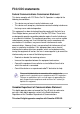
4.1 Managing and updating your BIOS 4.1.1 Using the computer system for the first time It is recommended that you save a copy of the original motherboard BIOS along with a Flash Memory Writer utility (AFLASH.EXE) to a bootable floppy disk in case you need to reinstall the BIOS later. AFLASH.EXE is a Flash Memory Writer utility that updates the BIOS by uploading a new BIOS file to the programmable flash ROM on the motherboard. This file works only in DOS mode.
5. Select 1. Save Current BIOS to File from the Main menu and press . The Save Current BIOS To File screen appears. 6. Type a filename and the path, for example, A:\XXX-XX.XXX, then press .
4.1.2 Updating BIOS procedures CAUTION! Update the BIOS only if you have problems with the motherboard and you are sure that the new BIOS revision will solve your problems. Careless updating may result to more problems with the motherboard! 1. FTP) (see ASUS CONTACT INFORMATION on page x for details) and save to the boot floppy disk you created earlier. 2. Boot from the floppy disk. 3. At the “A:\” prompt, type AFLASH and then press . 4. At the Main Menu, type 2 then press .
7. The utility starts to program the new BIOS information into the Flash ROM. The boot block is updated automatically only when necessary. This minimizes the possibility of boot problems in case of update failures. When the programming is done, the message “Flashed Successfully” appears. 8. Follow the onscreen instructions to continue. WARNING! If you encounter problems while updating the new BIOS, DO NOT turn off the system because this may cause boot problems.
4.2 BIOS Setup program This motherboard supports a programmable EEPROM that you can update using the provided utility described in section “4.1 Managing and updating your BIOS.” Use the BIOS Setup program when you are installing a motherboard, reconfiguring your system, or prompted to “Run Setup”. This section explains how to configure your system using this utility. Even if you are not prompted to use the Setup program, you may want to change the configuration of your computer in the future.
4.2.1 BIOS menu bar The top of the screen has a menu bar with the following selections: MAIN Use this menu to make changes to the basic system configuration. ADVANCED Use this menu to enable and make changes to the advanced features. POWER Use this menu to configure and enable Power Management features. BOOT Use this menu to configure the default system device used to locate and load the Operating System. EXIT Use this menu to exit the current menu or to exit the Setup program.
General help In addition to the Item Specific Help window, the BIOS setup program also provides a General Help screen. You may launch this screen from any menu by simply pressing or the + combination. The General Help screen lists the legend keys and their corresponding functions. Saving changes and exiting the Setup program See “4.7 Exit Menu” for detailed information on saving changes and exiting the setup program.
4.3 Main Menu When you enter the Setup program, the following screen appears. System Time [XX:XX:XX] Sets the system to the time that you specify (usually the current time). The format is hour, minute, second. Valid values for hour, minute and second are Hour: (00 to 23), Minute: (00 to 59), Second: (00 to 59). Use the or + keys to move between the hour, minute, and second fields. System Date [XX/XX/XXXX] Sets the system to the date that you specify (usually the current date).
4.3.1 Primary and Secondary Master/Slave Type [Auto] Select [Auto] to automatically detect an IDE hard disk drive. If automatic detection is successful, Setup automatically fills in the correct values for the remaining fields on this sub-menu. If automatic detection fails, this may be because the hard disk drive is too old or too new. If the hard disk was already formatted on an older system, Setup may detect incorrect parameters.
[User Type HDD] Manually enter the number of cylinders, heads and sectors per track for the drive. Refer to the drive documentation or on the drive label for this information. NOTE! After entering the IDE hard disk drive information into BIOS, use a disk utility, such as FDISK, to partition and format new IDE hard disk drives. This is necessary so that you can write or read data from the hard disk. Make sure to set the partition of the Primary IDE hard disk drives to active.
Translation Method [LBA] Select the hard disk drive type in this field. When Logical Block Addressing (LBA) is enabled, the 28-bit addressing of the hard drive is used without regard for cylinders, heads, or sectors. Note that LBA Mode is necessary for drives with more than 504MB storage capacity. Configuration options: [LBA] [LARGE] [Normal] [Match Partition Table] [Manual] Cylinders This field configures the number of cylinders. Refer to the drive documentation to determine the correct value.
SMART Monitoring [Disabled] This field allows you to enable or disable the S.M.A.R.T. (Self-Monitoring, Analysis and Reporting Technology) system that utilizes internal hard disk drive monitoring technology. This parameter is normally disabled because the resources used in the SMART monitoring feature may decrease system performance. Configuration options: [Disabled] [Enabled] PIO Mode [4] This option lets you set a PIO (Programmed Input/Output) mode for the IDE device.
4.3.2 Keyboard Features Boot Up NumLock Status [On] This field enables users to activate the Number Lock function upon system boot. Configuration options: [Off] [On] Keyboard Auto-Repeat Rate [12/Sec] This controls the speed at which the system registers repeated keystrokes. Options range from 6 to 30 characters per second.
Language [English] This field displays the BIOS language version. Supervisor Password [Disabled] / User Password [Disabled] These fields allow you to set passwords. To set a password, highlight the appropriate field and press . Type in a password then press . You can type up to eight alphanumeric characters. Symbols and other characters are ignored. To confirm the password, type the password again and press . The password is now set to [Enabled].
4.4 Advanced Menu CPU Speed This field displays the internal frequency of your CPU. CPU/PCI Frequency (MHz) [100/33] This feature tells the clock generator which frequency to send to the system bus and PCI bus. The bus frequency (external frequency) multiplied by the bus multiple equals the CPU speed. Increasing the ratio will increase the CPU Speed. The range may not be modified in BIOS, but only changes according to BSEL jumper settings.
CPU Fast Decode [Disabled] This field functions as a supplemntary speed enhancement device for streamlining CPU calculations. Configuration options: [Enabled] [Disabled] BIOS Update [Enabled] This field functions as an update loader integrated into the BIOS to supply the processor with the required data. When set to [Enabled], the BIOS loads the update on all processors during system bootup.
4.4.1 Summary of Warning Messages (Jumperless Operation only) The system may crash or hang up due to conflicts between settings and CPU compatibility: checksum errors, improper frequency settings, change of CPU and improper CPU speed settings. The system starts up in safe mode running at a bus speed of 100MHz and enters the BIOS Setup. Each time a system hangup occurs, BIOS interrupts the bootup process with a specific warning message.
4.4.2 Chip Configuration (Scroll down to view all items on the menu.) SDRAM Configuration [By SPD] This sets the optimal timing. The default setting is [By SPD], which automatically configures the timing by reading the contents in the SPD (Serial Presence Detect) device. The EEPROM on the memory module stores critical parameter information about the module, such as memory type, size, speed, voltage interface, and module banks.
Internal Graphic Over-clocking [Disable] This feature permits the grapical processor to participate in over-clocking. Configuration options: [Disable] [Enable] Internal VGA LCD TV Display Type [NTSC-M] The system automatically detects and sets up screen-type compatibility. Configuration options: [NTSC-M] [NTSC-J] [PAL-M] [PAL-BDGHI] [PAL-N] [PAL-NC] Video Memory Cache Mode [UC] USWC (uncaheable, speculative write combining) is a new cach technology for the processor’s video memory.
4.4.3 I/O Device Configuration Onboard FDC Swap A & B [No Swap] This field allows you to reverse the hardware drive letter assignments of your floppy disk drives. Configuration options: [No Swap] [Swap AB] Floppy Disk Access Control [R/W] Set this field to read and write the floppy disk (R/W). Change to [Read Only] for reading disks. Onboard Serial Port 1 [3F8H/IRQ4] Onboard Serial Port 2 [2F8H/IRQ3] These fields allow you to set the addresses for the onboard serial connectors.
Parallel Port Mode [ECP+EPP] This field allows you to set the operation mode of the parallel port. [Normal] allows normal-speed operation but in one direction only; [EPP] allows bidirectional parallel port operation; [ECP] allows the parallel port to operate in bidirectional DMA mode; [ECP+EPP] allows normal speed operation in a two-way mode. Configuration options: [Normal] [EPP] [ECP] [ECP+EPP] ECP DMA Select [3] This field allows you to configure the parallel port DMA channel for the selected ECP mode.
4.4.4 PCI Configuration Slot 1, Slot 2, Slot 3 [Auto] These fields automatically assign the IRQ for each PCI slot. The default setting for each field is [Auto], which utilizes auto-routing to determine IRQ assignments. Configuration options: [Auto] [NA] [3] [4] [5] [7] [9] [10] [11] [12] [14] [15] PCI/VGA Palette Snoop [Disabled] Some non-standard VGA cards, such as graphics accelerators or MPEG video cards, may not show colors properly. Setting this field to [Enabled] corrects this problem.
PCI DMA Resource Exclusion DMA x Reserved for Legacy Drive [No/ICU] These fields indicate whether or not the DMA channel displayed for each field is being used by a legacy (non-PnP) ISA card. The default setting indicates either that the DMA channel displayed is not used or an ICU is being used to determine if an ISA device is using the channel instead.
4.4.5 Shadow Configuration Video ROM BIOS Shadow [Enabled] This field allows you to change the video BIOS location from ROM to RAM. Relocating to RAM enhances system performance, as information access is faster than the ROM. Configuration options: [Disabled] [Enabled] C8000-DFFFF Shadow [Disabled] These fields are used for shadowing other expansion card ROMs. If you install other expansion cards with ROMs on them, you will need to know which addresses the ROMs use to shadow them specifically.
4.5 Power Menu The Power menu allows you to reduce power consumption. This feature turns off the video display and shuts down the hard disk after a period of inactivity. ACPI Suspend To RAM [Disabled] This field allows you to enable or disable the ACPI Suspend-to-RAM feature. To support this feature, the +5VSB of the power supply should have the capacity to provide more than 720mA current.
PWR Button < 4 Secs [Soft Off] When set to [Soft off], the ATX switch can be used as a normal system poweroff button when pressed for less than 4 seconds. [Suspend] allows the button to have a dual function where pressing less than 4 seconds will place the system in sleep mode. Regardless of the setting, holding the ATX switch for more than 4 seconds will power off the system.
4.5.1 Power Up Control AC PWR Loss Restart [Disabled] This allows you to set whether you want your system to reboot after the power has been interrupted. [Disabled] leaves your system off and [Enabled] reboots your system. [Previous State] sets your system back to the state it is before the power interruption. Configuration options: [Disabled] [Enabled] [Previous State] Power Up On PCI Card [Disabled] When set to [Enabled], this parameter allows you to turn on the system through a PCI modem.
4.5.2 Hardware Monitor MB Temperature [xxxC/xxxF] CPU Temperature [xxxC/xxxF] The onboard hardware monitor automatically detects the MB (motherboard), CPU, and JTPWR (power supply) temperatures. CPU Fan Speed [xxxxRPM] The onboard hardware monitor automatically detects the speeds of the CPU fan, chassis fan, and chassis fan measured in rotations per minute (RPM). VCORE Voltage +3.
4.6 Boot Menu Boot Sequence The Boot menu allows you to select among the four possible types of boot devices listed using the up and down arrow keys. By using the <+> or key, you can promote devices and by using the <-> key, you can demote devices. Promotion or demotion of devices alters the priority which the system uses to search for a boot device on system power up. Configuration fields include Removable Devices, IDE Hard Drive, ATAPI CD-ROM, and Other Boot Device.
Boot Virus Detection [Enabled] This field allows you to set boot virus detection, ensuring a virus-free boot sector. The system halts and displays a warning message when it detects a virus. If this occurs, you can either allow the operation to continue or use a virus-free bootable floppy disk to restart and investigate your system.
4.7 Exit Menu When you have made all of your selections from the various menus in the Setup program, save your changes and exit Setup. Select Exit from the menu bar to display the following menu. NOTE! Pressing does not immediately exit this menu. Select one of the options from this menu or from the legend bar to exit. Exit Saving Changes Once you are finished making your selections, choose this option from the Exit menu to ensure the values you selected are saved to the CMOS RAM.
Load Setup Defaults This option allows you to load the default values for each of the parameters on the Setup menus. When you select this option or if you press , a confirmation window appears. Select [Yes] to load default values. Select Exit Saving Changes or make other changes before saving the values to the non-volatile RAM. Discard Changes This option allows you to discard the selections you made and restore the previously saved values. After selecting this option, a confirmation appears.
Chapter 5 Software support
ASUS A7N266-VM motherboard
5.1 Install an operating system This motherboard supports Windows 98/ME/ and 2000/XP operating system (OS). Always install the latest OS version and corresponding updates so you can maximize the features of your hardware. 5.1.1 Windows 98 first time installation When you start Windows for the first time after installing the motherboard, Windows 98 detects all Plug-n-Play devices devices. Follow the Add New Hardware wizard to install the necessary device drivers. When prompted to restart, select No.
5.3 A7N266-VM Motherboard Support CD NOTE: The support CD contents are subject to change without notice. To begin using your support CD disc, just insert it into your CD-ROM drive and the support CD installation menu should appear. If the menu does not appear, double-click or run D:\ASSETUP.EXE (assuming that your CD-ROM drive is drive D:). 5.3.1 Installation Menu • • • • • • • NVIDIA nForce Drivers: Installs the video drivers. The Windows ME™ OS must be used with these drivers.
• • • Adobe Acrobat Reader Vx.xx: Installs the Adobe Acrobat Reader software necessary to view user’s manuals saved in PDF format. Updated or other language versions of this motherboard's manual is available in PDF format at any of our web sites. Cyberlink Video and Audio Applications: Installs Cyberlink PowerPlayer SE and Cyberlink VideoLive Mail. ASUS Screen Saver: Installs a nifty ASUS screen saver.
5.3.3 Installation of PCI Drivers: Win98 Use the Device Manager to uninstall all previously installed system drivers to prevent conflict with the installation and operation of nVidia® drivers. Three nVidia® drivers need to be installed to operate with the Win98: 1. PCI System Management Bus. 2. PCI Standard Host CPU Bridge. 3. PCI Standard RAM Controller. ITEM 1: PCI System Management Bus 1. Go to the “Device Manager.” 2. Select “PCI System Management Bus” in “Other Devices.” 3. Click on “Properities.” 4.
ITEM 3: PCI Standard Ram Controller 1. Go to the “Device Manager.” 2. Select PCI standard RAM Controller in “System Devices” 3. Click on “Properities.” 4. Click on “Driver.” 5. Select “Update Driver.” 6. Select “Search for a better driver than the one your device is using now” option. 7. Click on “Specify the location” and then type or browse for the path on the CD-ROM Drive:\Drivers\Chipset\Nvidia\win9x\MemoryController. 8. Click “Next.” 9.
5.3.5 Installation of NVIDIA MCP MAC Driver: Win98 1. Go to the Device Manager. 2. Select “PCI Ethernet controller” in “Other Devices.” 3. Click on “Properities.” 4. Click on “Driver.” 5. Select “Update Driver.” 6. Select “Search for a better driver than the one your device is using now” option. 7. Click on “Specify the location” and then type or browse for the path on the CD-ROM Drive:\Drivers\Chipset\Nvidia\103\win9xme. This installs the driver. 8. Click “Next.” 9.
5.4 ASUS PC Probe ASUS PC Probe is a convenient utility to continuously monitor your computer system’s vital components, such as fan rotations, Voltages, and temperatures. It also has a utility that lets you review useful information about your computer, such as hard disk space, memory usage, and CPU type, CPU speed, and internal/external frequencies through the DMI Explorer. 5.4.
5.4.2 Using ASUS PC Probe Monitoring Monitor Summary Shows a summary of the items being monitored. Temperature Monitor Shows the PC’s temperature. Temperature Warning threshold adjustment (Move the slider up to increase the threshold level or down to decrease the threshold level) Fan Monitor Shows the PC’s fan rotation. Fan Warning threshold adjustment (Move the slider up to increase the threshold level or down to decrease the threshold level) Voltage Monitor Shows the PC’s voltages.
Settings Lets you set threshold levels and polling intervals or refresh times of the PC’s temperature, fan rotation, and voltages. CPU Cooling System Setup Lets you select when to enable software CPU cooling. When When CPU Overheated is selected, the CPU cooling system is enabled whenever the CPU temperature reaches the threshold value. History Lets you record the current monitoring activity of a certain component of your PC for future reference.
Memory Shows the PC’s memory load, memory usage, and paging file usage. Device Summary Shows a summary of devices in your PC. DMI Explorer Shows information pertinent to the PC, such as CPU type, CPU speed, and internal/external frequencies, and memory size. Utility Lets you run programs outside of the ASUS Probe modules. To run a program, click Execute Program.
5.4.3 ASUS PC Probe Task Bar Icon Right-clicking the PC Probe icon will bring up a menu to open or exit ASUS PC Probe and pause or resume all system monitoring. When the ASUS PC Probe senses a problem with your PC, portions of the ASUS PC Probe icon changes to red, the PC speaker beeps, and the ASUS PC Probe monitor is displayed.
5.5 ASUS Live Update ASUS LiveUpdate is a utility that allows you to update your motherboard’s BIOS and drivers. The use of this utility requires that you are properly connected to the Internet through an Internet Service Provider (ISP). 1. Start ASUS Update. Launch the utility from your Windows Start menu:Programs/AsusUpdate. 2. Select an update method. 3. If you selected “downloading from the Internet,” you will need to select an Internet site.
5.6 3Deep Color Tuner The 3-Deep color tuner is designed to match your CRT or LCD color monitor to maximize the color quality of all graphical applications. Users may also tune their internet applications to match “true” internet source colors with the color displayed on the monitor. Simply run the setup program from the start menu and follow the instructions on the various setup/test screens. 5.6.1 3Deep Color Tuning 1. Select the type of monitor connected to the computer, either CRT or LCD. 2.
4. Select the color squares which most closely blend and match with the background. 5. The next step repeats the color matching process to achieve full color quality. 6. The tuning process is complete. Click on the bottom left button to connect to the internet and follow the instructions. 5.6.2 The 3Deep Control Panel Using the Windows Start button, activate the 3Deep Control Panel program from the 3Deep Applications group on the Main Program menu.
5.7 CyberLink PowerPlayer SE CyberLink PowerPlayer SE is an intelligent software player that can automatically detect and playback all kinds of video/audio files, CD and MP3 files as well. This is the only software you need for all types of video and audio files. No need to waste time identifying your file types. 5.7.1 Starting CyberLink PowerPlayer SE To start CyberLink Power Player, click the Windows Start button, point to Programs, and then CyberLink PowerPlayer SE, and then click PowerPlayer. 5.7.
5.8 CyberLink VideoLive Mail CyberLink’s VideoLive Mail Plus Ver 3.0 (a.k.a. VLM 3) is a convenient and excellent way to create professional quality video mails from PC video/audio input devices and to send the mails to any recipients via VLM 3’s built-in email system through the Internet. VLM 3’s mails comprise video, sound, or snapshot information; and thus may convey the most profound information to target audiences.
5.8.1 Starting VideoLive Mail To start VideoLive Mail, click the Windows Start button, point to Programs, and then CyberLink VideoLive Mail, and then click VideoLive Mail x.x. VLM 3’s Setup Wizard will start and guide you through configuring the video and audio input peripherals and to setup the e-mail environment. 1. Setup Wizard first will prompt a dialog to confirm that you want to configure the hardware and E-mail setting. Click Yes to continue the system parameter configuration. 2.
84 Chapter 5: Software reference
Chapter 6 Appendix
ASUS A7N266-VM motherboard
6.1 Glossary 1394 1394 is the IEEE designation for a high performance serial bus tht offers data transfers at 100/200/400 Mbps. This serial bus defines both a back plane physical layer and a point-to-point cable-connected virtual bus. The primary application of the cable version is the integration of I/O connectivity at the back panel of personal computers using a low-cost, scalable, high-speed serial interface.
Bus Master IDE PIO (Programmable I/O) IDE requires that the CPU be involved in IDE access and waiting for mechanical events. Bus master IDE transfers data to/from the memory without interrupting the CPU. Bus master IDE driver and bus master IDE hard disk drives are required to support bus master IDE mode. Byte (Binary Term) One byte is a group of eight contiguous bits. A byte is used to represent a single alphanumeric character, punctuation mark, or other symbol. Cache Memory.
I/O (Input/Output) The data transfers from the input devices like a keyboard, mouse, or scanner, to the output devices like a printer or the monitor screen. I/O Address The specific memory location for a particular device. Two devices cannot share the same I/O address space. IrDA (Infrared Data Association) An internaltional organization that creates and promotes inter-operable, low cost, infrared data interconnection standards that support a walk-up, point-to-point model.
RDRAM (Rambus DRAM) Developed by Rambus, Inc., this type of memory can deliver up to 1.6GB of data per second. RDRAM is the first interface standard that can be directly implemented on high performance VLSI components such as, CMOS DRAMs, memory controllers, and graphics/video ICs. RAM (Random Access Memory). The computer’s primary storage area used to write, store, and retrieve information and program instructions which are passed to the CPU for processing.
6.2 Troubleshooting 1. Windows 2000™ system fails to run the FIFA 2000™ video game: the program exits after start up. However, the FIFA 2002™ version of the video game functions flawlessly. 2. If the NEC® FDA-5101 USB keyboard is used to install Windows XP™, the keyboard cannot be detected during the installation process. 3. If installing a PCI card with a game port, the PCI game port cannot be used due to a limitation of the nVidia® chipset. However, the game port on the MB will always function. 4.
90 Chapter 6: Appendix
Index
ASUS A7N266-VM motherboard
Index Symbols 3Deep Color Tuner Using 79 A Accelerated Graphics Port AGP Capability 53 ASUS PC Probe Using 73 ASUS Update Using 78 ATAPI CD-ROM 63 Audio setting 19 Audio setting jumper 19 Automatic Power Up 63 B BIOS Advanced Menu 49 Beep Codes 33 Boot Menu 63 Boot Sequence 63 Exit Menu 65 Legend Bar 40 Main Menu 42 Menu Bar 40 Power Menu 59 Setup Defaults, loading 66 Setup Program 39 Sub-menu launching 41 Updating 35 BIOS Beep Codes 33 Boot Device Selection 63 Boot Up NumLock Status 47 Boot Virus Detecti
E L Expansion card installation 15 Expansion slots 15 LAN Jumper Setting 21 Legacy Diskette 42 LiveUpdate 79 Using 79 F Floppy 3 Mode 42 Floppy Disk Drive Connector 9, 27, 30 H Hard Disk Drives (HDDs) CHS Capacity 45 Cylinders 45 Heads 45 LBA Capacity 45 Primary/Secondary Master 43 Primary/Secondary Slave 43 Sectors 45 Types 43 Hardware Monitor 62 Motherboard IRQ Table 17 layout 9 placement 7 screws 7 Mouse Connector 23 Multi-Sector Transfers 45 O Onboard LED 11 Operating system installation 67 I P
PS/2 Mouse 23 Function Control 50 PS/2 Mouse Port 2 R V Video ROM BIOS Shadow 58 VideoLive Mail v, 82 Using v, 82 RTC RAM Clearing 9, 22 S SDRAM Configuration 52 Serial Ports 54 Connectors 24, 25 slots AGP 17 PCI 17 SMART Monitoring 46 SMBus Connector 29 Support CD 67 Welcome screen 67 System Date 42 System memory configurations 13 System Time 42 U UART2 54, 56 Ultra DMA Mode 46 Universal Serial Bus (USB) 24 Ports 24 USB device wake up 21 USB Legacy Support 50, 52 Using 3Deep Color Tuner 79 ASUS Update
94 Index