User Manual Motherboard A7N8X-VM 400
E1543 Checklist First Edition February 2004 Copyright © 2004 ASUSTeK COMPUTER INC. All Rights Reserved. No part of this manual, including the products and software described in it, may be reproduced, transmitted, transcribed, stored in a retrieval system, or translated into any language in any form or by any means, except documentation kept by the purchaser for backup purposes, without the express written permission of ASUSTeK COMPUTER INC. (“ASUS”).
Contents Features Contents ......................................................................................... iii Notices ............................................................................................ v Safety information .......................................................................... vi ASUS contact information ............................................................ viii A7N8X-VM 400 specifications summary ........................................
Contents Safeguards 2.4 Advanced Menu ................................................................. 2-8 2.4.1 Chipset ................................................................... 2-8 2.4.2 Onboard Devices Configuration ............................. 2-9 2.4.3 PCIPnP .................................................................2-11 2.5 Power Menu ..................................................................... 2-12 2.5.1 Power Up Control ................................................
Notices Federal Communications Commission Statement This device complies with Part 15 of the FCC Rules. Operation is subject to the following two conditions: • This device may not cause harmful interference, and • This device must accept any interference received including interference that may cause undesired operation. This equipment has been tested and found to comply with the limits for a Class B digital device, pursuant to Part 15 of the FCC Rules.
Safety information Electrical safety • To prevent electrical shock hazard, disconnect the power cable from the electrical outlet before relocating the system. • When adding or removing devices to or from the system, ensure that the power cables for the devices are unplugged before the signal cables are connected. If possible, disconnect all power cables from the existing system before you add a device.
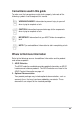
Conventions used in this guide To make sure that you perform certain tasks properly, take note of the following symbols used throughout this manual. WARNING/DANGER: Information to prevent injury to yourself when trying to complete a task. CAUTION: Information to prevent damage to the components when trying to complete a task. IMPORTANT: Information that you MUST follow to complete a task. NOTE: Tips and additional information to aid in completing a task.
ASUS contact information ASUSTeK COMPUTER INC. (Asia-Pacific) Address Telephone Web site 150 Li-Te Road, Peitou, Taipei, Taiwan 112 +886-2-2894-3447 www.asus.com.
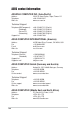
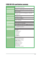
A7N8X-VM 400 specifications summary CPU Socket A Type 462 for AMD Athlon™/Athlon™ XP CPUs 400/333/266 MHz FSB Support Chipset NVIDIA® nForce2 IGP North bridge controller NVIDIA® nForce2 MCP2 (MCP2-T optional) South bridge Front Side Bus (FSB) 400/333/266 Mhz Memory 2 x 184-pin DDR DIMM Sockets Maximum 2 GB unbuffered PC2700/2100 non-ECC DDR RAM memory. Expansion slots 3 x PCI 1 x AGP 8X (1.
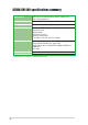
A7N8X-VM 400 specifications summary BIOS features 4Mb Flash EEPROM, AMI BIOS, ACPI 2.0, DMI, Green, PnP, TCAV, SMBIOS 2.3 Industry standard PCI 2.2, USB 2.0/1.1 Manageability DMI 2.
Chapter 1 This chapter describes the features of the A7N8X-VM 400 motherboard. It includes brief descriptions of the motherboard components, and illustrations of the layout, jumper settings, and connectors.
1.1 Welcome! Thank you for buying the ASUS® A7N8X-VM 400 motherboard! The ASUS A7N8X-VM 400 motherboard is loaded with the most advanced technologies to deliver maximum performance for socket A processors. This motherboard is packed with value-added features for guaranteed consumer satisfaction. The following sections provide technical information about the motherboard important for future upgrades or system reconfiguration.
1.4 Motherboard components Before you install the motherboard, learn about its major components and available features to facilitate the installation and future upgrades. Refer to the succeeding pages for the component descriptions.
1-4 1 Onboard LED. This onboard LED lights up if there is a standby power on the motherboard. This LED acts as a reminder to turn off the system power before plugging or unplugging devices. 2 ATX power connector. This standard 20-pin connector connects to an ATX 12V power supply. The power supply must have at least 1A on the +5V standby lead (+5VSB). 3 CPU Socket. Socket 462 (Socket A) Zero Insertion Force (ZIF) socket for the AMD Athlon™/AMD Athlon XP™ processors. 4 NorthBridge Controller.
12 System Buzzer. The system buzzer allows you to hear system warning beeps when a PC speaker is not available. 13 Audio CODEC. The Realtek ALC650 6-channel Audio CODEC is an AC’97 compliant audio CODEC designed for PC multimedia systems. 14 PCI slots. These 32-bit PCI 2.2 expansion slots support bus master PCI cards like SCSI or LAN cards with 133MB/s maximum output. 15 LAN chip. The Realtek 8201BL PHY Fast Ethernet controller allows connection to a Local Area Network (LAN) through a network hub.
1.5 Motherboard layout 24.5cm (9.6in) PS/2 T: Mouse B: Keyboard Socket 462 Bottom: USB34 Top: USB1 RJ-45 USB2 Top:Line In Center:Line Out Below:Mic In U46 nVidia nForce2 IGP 2 3 4 5 CHA_FAN A7N8X-VM 24.5cm (9.
1.6 Before you proceed Take note of the following precautions before you install motherboard components or change any motherboard settings. 1. Unplug the power cord from the wall socket before touching any component. 2. Use a grounded wrist strap or touch a safely grounded object or to a metal object, such as the power supply case, before handling components to avoid damaging them due to static electricity. 3. Hold components by the edges to avoid touching the ICs on them. 4.
1.8 System memory The motherboard has two Double Data Rate (DDR) DIMM sockets that supports up to 2GB non-ECC PC2700/2100 DDR DIMMs. 104 Pins A7N8X-VM 400 80 Pins A7N8X-VM 400 184-Pin DDR DIMM Sockets A DDR DIMM is keyed with a notch so that it fits in only one direction. DO NOT force a DIMM into a socket to avoid damaging the DIMM. Installing a DIMM 1. Unlock a DIMM socket by pressing the retaining clips outward. 2. Align a DIMM on the socket.
1.9.
1.9.3 AGP slot This motherboard has an Accelerated Graphics Port (AGP) slot that supports +1.5V AGP 8X cards. Note the notches on the card golden fingers to ensure that they fit the AGP slot on your motherboard. AGP Card without Retention Notch A7N8X-VM 400 A7N8X-VM 400 Accelerated Graphics Port (AGP8X) 1.9.4 PCI slots Three 32-bit PCI slots are available on this motherboard. The slots support PCI cards such as LAN card, SCSI card, USB card, and other cards that comply with PCI specifications.
1.10 Jumpers This section describes and illustrates the jumpers on the motherboard. 1. USB device wake-up (3-pin USBPW12,USBPW34,USBPWR56) Set these jumpers to +5V to wake up the computer from S1 sleep mode (CPU stopped, DRAM refreshed, system running in low power mode) using the connected USB devices. Set to +5VSB to wake up from S3 sleep mode (no power to CPU, DRAM in slow refresh, power supply in reduced power mode).
2. Clear RTC RAM (CLRTC1) This jumper clears the Real Time Clock (RTC) RAM of date, time and system setup parameters in CMOS. The RAM data in CMOS is powered by the onboard button cell battery. To erase the RTC RAM: 1. Turn OFF the computer and unplug the power cord. 2. Remove the battery. 3. Move the jumper caps from [1-2] to [2-3] momentarily. Replace the jumper cap to the original position, [1-2]. 4. Re-install the battery. 5. Plug the power cord and turn ON the computer. 6.
1.11 Connectors This section describes and illustrates the connectors on the motherboard. 1. IDE connectors (40-1 pin PRI_IDE, SEC_IDE) This connector supports the provided UltraATA 133/100/66/33 IDE hard disk ribbon cable. Connect the cable’s blue connector to the primary (recommended) or secondary IDE connector, then connect the gray connector to the UltraATA 133/100/66/33 slave device (hard disk drive) and the black connector to the UltraATA 133/100/66/33 master device.
2. Floppy disk drive connector (34-1 pin FLOPPY1) This connector supports the provided floppy drive ribbon cable. After connecting one end to the motherboard, connect the other end to the floppy drive. (Pin 5 is removed to prevent incorrect insertion when using ribbon cables with pin 5 plug.) FLOPPY1 NOTE: Orient the red markings on the floppy ribbon cable to PIN 1 A7N8X-VM 400 PIN 1 A7N8X-VM 400 Floppy Disk Drive Connector 3.
4. USB headers (10-1 pin USB34, USB56) 1 A7N8X-VM 400 USB 2.0 Headers USB56 USB+5V USB_P3USB_P3+ GND USB34 1 USB+5V USB_P5USB_P5+ GND A7N8X-VM 400 USB+5V USB_P6USB_P6+ GND NC USB+5V USB_P4USB_P4+ GND NC If the USB 2.0 port connectors on the back panel are inadequate, two USB headers are available for four additional USB port connectors. Connect a 2port USB connector set to a USB header and mount the USB bracket to an open slot in the chassis. 5.
6. CPU and Chassis Fan Connectors (3-pin CPU_FAN1, CHA_FAN) The fan connectors support cooling fans of 350mA~740mA (8.88W max.) or a total of 1A~2.22A (26.64W max.) at +12V. Connect the fan cables to the fan connectors on the motherboard, making sure that the black wire of each cable matches the ground pin of the connector. Rotation +12V GND CPU_FAN1 A7N8X-VM 400 CHA_FAN1 GND +12V Rotation A7N8X-VM 400 12-Volt Cooling Fan Power Do not forget to connect the fan cables to the fan connectors.
8. Front panel audio connectors (10-1 pin FPAUDIO) BLINE_OUT_L AGND +5VA BLINE_OUT_R This is an interface for front panel audio cable that allows convenient connection and control of audio devices. A7N8X-VM 400 MIC2 MICPWR Line out_R NC Line out_L FP_AUDIO A7N8X-VM 400 Front Panel Audio Connector 9. OnBoard LED The green Light Emitting Diode (LED) lights-ON if there is standby power and lights-OFF when the power is turned off.
10. Internal audio connectors (4 pin CD1, AUX1) These connectors allow you to receive stereo audio input from sound sources such as a CD-ROM, TV tuner, MPEG card or modem. AUX1 (White) CD1 (Black) Left Audio Channel A7N8X-VM 400 Ground Right Audio Channel A7N8X-VM 400 Internal Audio Connectors 11. Digital Audio Connector (6-1 pin SPDIF1) SPDIF_OUT +5V SPDIF_IN GND A7N8X-VM 400 GND This connector is for optional S/PDIF audio module that allows digital instead of analog sound input and output.
12. TV out connector (6-1 pin U46) This 6-1 pin connector connects to the front panel daughter card with the audio tv-out port. TV_OUT 1 A7N8X-VM 400 A7N8X-VM 400 TV Out Connector 13. Serial Port 2 connector (10-1 pin COM2) This connector accommodates a second serial port using an optional serial port bracket. Connect the bracket cable to this connector then install the bracket into a slot opening at the back of the system chassis.
14. System panel connector (20-pin PANEL1) This connector accommodates several system front panel functions. Reset SW PLEDKeylock Ground IDE LED SMI Lead A7N8X-VM 400 System Panel Connectors • Reset Ground A7N8X-VM 400 ExtSMI# Ground PWR Ground +5V IDELED PLED+ Power LED Speaker Connector +5V Ground Ground Speaker Keyboard Lock ATX Power Switch* * Requires an ATX power supply. System Power LED Lead (3-1 pin PLED) This 3-1 pin connector connects to the system power LED.
Chapter 2 This chapter tells how to change system settings through the BIOS Setup Menus. Detailed descriptions of the BIOS parameters are also provided.
2.1 Managing and Updating your BIOS It is recommended that you save a copy of the motherboard’s original BIOS to a bootable floppy disk in case you need to reinstall the original BIOS later. The BIOS information in the above screen is for reference only. What you see on your screen may not be exactly the same as shown. 2.1.1 Using AFUDOS to update the BIOS Updating the BIOS Update the BIOS only if you are sure that the new BIOS revision will solve your problems.
2.2 BIOS Setup program Use the BIOS Setup program when you are installing a motherboard, reconfiguring your system, or prompted to “Run Setup”. This section explains how to configure your system using this utility. Even if you are not prompted to use the Setup program, you may want to change the configuration of your computer in the future. For example, you may want to enable the security password feature or make changes to the power management settings.
2.2.2 Legend bar At the bottom of the Setup screen is a legend bar. The keys in the legend bar allow you to navigate through the various setup menus. The following table lists the keys found in the legend bar with their corresponding functions.
Sub-menu Note that a right pointer symbol (as shown on the left) appears to the left of certain fields. This pointer indicates that you can display a sub-menu from this field. A sub-menu contains additional options for a field parameter. To display a sub-menu, move the highlight to the field and press . The submenu appears. Use the legend keys to enter values and move from field to field within a sub-menu as you would within a menu. Use the key to return to the main menu.
System Date [XX/XX/XXXX] Sets the system to the date that you specify (usually the current date). The format is month, day, year. Valid values for month, day, and year are Month: (1 to 12), Day: (1 to 31), Year: (up to 2099). Use the or + keys to move between the month, day, and year fields. Legacy Diskette A [1.44M, 3.5 in.] Sets the type of floppy drive installed. Configuration options: [Disabled] [360K, 5.25 in.] [1.2M , 5.25 in.] [720K , 3.5 in.] [1.44M, 3.5 in.] [2.88M, 3.5 in.
Block (Multi-Sector Transfer) [Auto] This field configures the Multi-Sector Transfer Block. Select [Auto] to enable the data to transfer from and to the device occurs multiple sectors at a time if the device supports it. When [Disabled], the data transfer from and to the device occurs one sector at a time. PIO Mode [Auto] This option lets you set a PIO (Programmed Input/Output) mode for the IDE device. Modes 0 through 4 provide successive increase in performance.
2.4 Advanced Menu Chipset Onboard Devices Configuration PCIPnP 2.4.1 Chipset nVidia nForce2 Chipset Configuration Video Frame Buffer Size Graphics Aperture Size MDA Access Control Primary Video OnBoard TV-out Format [64MB] [64MB] [PCI] [PCI] [PAL] Video Frame Buffer Size [ 64MB] This field sets the size of the video frame buffer. The settings on this field is valid only for motherboard models with onboard VGA controller.
MDA Access Control [PCI] This field selects the MDA Access cycles direction. Configuration options: [AGP] [PCI] Primary Video [PCI] This will switch the PCI Bus scanning order while searching for a video card. This allows the user to select the type of Primary VGA in case of multiple video controllers. Configuration options: [PCI] [AGP/Onboard] Onboard TV-out format [PAL] This field sets the onboard TV-out format. Configuration options: [PAL] [NTSC] 2.4.
Parallel Port Mode [ECP] This field allows the BIOS to select the Parallel Port Mode. Configuration options: [Normal] [EPP] [ECP] [EPP+ECP] ECP Mode [DMA3] This field allows the BIOS to select the Parallel Port ECP DMA. Configuration options: [DMA0] [DMA1] [DMA3] Parallel Port IRQ [IRQ7] This field allows the BIOS to select the Parallel Port IRQ. Configuration options: [IRQ5l] [IRQ7] SMBUS Interface [Enabled] This field allows you to enable or disable the SMBus interface.
2.4.3 PCIPnP Advanced PCI/PnP Settings WARNING: Setting wrong values in the sections below may cause system to malfunction.
PCI IDE BusMaster [Enabled] This field allows the BIOS, when [Enabled], to use PCI busmastering for reading and writing to IDE drives. Configuration options: [Disabled] [Enabled] Offboard PCI/ISA IDE Card [Auto] This field allows the setting of the proper slot of installed PCI IDE cards. Some PCI IDE cards require this to be set to the PCI slot number that is holding the card.
2.5.1 Power Up Control Power Up Control Restore On AC/Power Loss Resume on Keyboard Resume on PS/2 Mouse PME Resume Ring In Resume OnBoard LAN Resume RTC Resume [Last State] [Disabled] [Disabled] [Disabled] [Disabled] [Disabled] [Disabled] Restore on AC Power Loss [Last State] When set to Power Off, the system goes into off state after an AC power loss. When set to Power On, the system goes on after an AC power loss.
Onboard LAN Resume [Disabled] This parameter enables or disables the onboard LAN to generate a wake event. This feature requires an ATX power supply that provides at least 1A on the +5VSB lead. Configuration options: [Disabled] [Enabled] RTC Resume [Disabled] This parameter enables or disables RTC to generate a wake event. This feature requires an ATX power supply that provides at least 1A on the +5VSB lead. Configuration options: [Disabled] [Enabled] 2.5.
2.6 Boot Menu Boot Device Priority 1st Boot Device 2nd Boot Device 3rd Boot Device [First Floppy Drive] [PM-ST320413A] [PS-ASUS CD-S340] Boot Settings Configuration Security 1st, 2nd, 3rd Boot Device This field specifies the boot sequence from the available devices. Additional plug-in boot devices installed appear in sequence after the list of current boot devices . Configuration fields include FLOPPY DRIVE, IDE Hard Drive, ATAPI CD-ROM, and Other Boot Device. 2.6.
AddOn ROM Display Mode [Force BIOS] This field sets the display mode for option ROM. Configuration options: [Force BIOS] [Keep Current] Bootup Num-Lock [On] This field selects the power-on state for the NumLock key. Configuration options: [Off] [On] PS/2 Mouse Support [Auto] This sets the PS/2 mouse support. Configuration options: [Disabled] [Auto] Wait for ‘F1’ If Error [Enabled] This field sets whether to wait for F1 key to be pressed if an error occurs.
2.6.2 Security Security Settings Supervisor Password : Not Installed User Password : Not Installed Change Supervisor Password Clear User Password Boot Sector Virus Protection [Disabled] Change Supervisor Password / User Password These fields allow you to set passwords. To set a password, highlight the appropriate field and press . A pop-up window will appear; Type in a password then press . You can type up to eight alphanumeric characters. Symbols and other characters are ignored.
Change Supervisor Password Select this item to set or change the supervisor password. The Supervisor Password item on top of the screen shows the default Not Installed. After you have set a password, this item shows Installed. To set a Supervisor Password: 1. Select the Change Supervisor Password item and press Enter. 2. On the password box that appears, type a password composed of letters and/ or numbers, then press Enter. Your password should have at least six characters. 3.
User Access Level (Full Access] This item allows you to select the access restriction to the Setup items. Configuration options: [No Access] [View Only] [Limited] [Full Access] No Access prevents user access to the Setup utility. View Only allows access but does not allow change to any field. Limited allows change to only selected fields, such as Date and Time. Full Access allows viewing and changing all the fields in the Setup utility.
2.7 Exit Menu When you have made all of your selections from the various menus in the Setup program, save your changes and exit Setup. Select Exit from the menu bar to display the following menu. Exit Options Exit & Save Changes Exit & Discard Changes Discard Changes Load Setup Defaults Pressing does not immediately exit this menu. Select one of the options from this menu or from the legend bar to exit.
Discard Changes This option allows you to discard the selections you made and restore the previously saved values. After selecting this option, a confirmation appears. Select [Yes] to discard any changes and load the previously saved values. Load Setup Defaults This option allows you to load the default values for each of the parameters on the Setup menus. When you select this option or if you press , a confirmation window appears. Select [Yes] to load default values.
2-22 Chapter 2: BIOS information
Chapter 3 This chapter describes the contents of the support CD that comes with the motherboard package.
3.1 Installing an operating system This motherboard supports Windows 98SE/ME/2000/XP as well as Linux Red Hat, SuSE, TurboLinux and Caldera operating systems (OS). Always install the latest OS version and corresponding updates so you can maximize the features of your hardware. Because motherboard settings and hardware options vary, use the setup procedures presented in this chapter for general reference only. Refer to your OS documentation for more information. 3.
3.2.2 Drivers menu The drivers menu shows the available device drivers if the system detects installed devices. Install the necessary drivers to activate the devices. Screen display and driver options may not be the same for other operating system versions. 3.2.3 Utilities menu The Utilities menu shows the applications and other software that the motherboard supports.
Temperature Monitor Shows the PC temperature (for supported processors only). Temperature Warning threshold adjustment (Move the slider up to increase the threshold level or down to decrease the threshold level) Fan Monitor Shows the PC fan rotation. Fan Warning threshold adjustment (Move the slider up to increase the threshold level or down to decrease the threshold level) Voltage Monitor Shows the PC voltages.
History Lets you record the monitoring activity of a certain component of your PC for future reference. Fan Control Lets you enable/disable Smart Fan Control. Smart Fan Control adjusts the fan speed automatically based on the current CPU temperature and predefined threshold. Hard Drives Shows the used and free space of the PC’s hard disk drives and the file allocation table or file system used. Information Memory Shows the PC memory load, memory usage, and paging file usage.
Device Summary Shows a summary of devices present in your PC. DMI Explorer Shows information pertinent to the PC, such as CPU type, CPU speed, and internal/external frequencies, and memory size. Utility Lets you run programs outside of the ASUS Probe modules. To run a program, click Execute Program. NOTE: This feature is currently unavailable. ASUS PC Probe Task Bar Icon Right clicking the PC Probe icon brings up a menu to open or exit ASUS PC Probe and pause or resume all system monitoring.
ASUS Update The ASUS Update is a utility that allows you to update the motherboard BIOS and drivers. This utility requires an Internet connection either through a network or an Internet Service Provider (ISP). Follow these steps to use the ASUS Update. 1. Launch the utility from your Windows Start menu: Programs/AsusUpdate Vx.xx.xx/ AsusUpdate The ASUS Update initial screen appears. 2. Select your desired update method, then click Next. 3.
If you selected the option to update the BIOS from a file, a window pops up prompting you to locate the file. Select the file, click Save, then follow the screen instructions to complete the update process.