User Guide Motherboard A7N8X-VM/400
E1480 Checklist First Edition V1 December 2003 Copyright © 2003 ASUSTeK COMPUTER INC. All Rights Reserved. No part of this manual, including the products and software described in it, may be reproduced, transmitted, transcribed, stored in a retrieval system, or translated into any language in any form or by any means, except documentation kept by the purchaser for backup purposes, without the express written permission of ASUSTeK COMPUTER INC. (“ASUS”).
Contents Features Notices ........................................................................................................ v Safety information ...................................................................................... vi About this guide ......................................................................................... vii A7N8X-VM/400 specification summary .................................................... viii Chapter 1: Product introduction 1.1 Welcome! ..................
Contents 2.3 Main menu ................................................................................... 2-10 2.4 2.3.1 Primary and Secondary IDE Master/Slave .................... 2-11 2.3.2 System Information ........................................................ 2-12 Advanced menu ........................................................................... 2-13 2.5 2.4.1 Chipset ........................................................................... 2-13 2.4.2 Onboard Devices Configuration ...
Notices Federal Communications Commission Statement This device complies with FCC Rules Part 15. Operation is subject to the following two conditions: • This device may not cause harmful interference, and • This device must accept any interference received including interference that may cause undesired operation. This equipment has been tested and found to comply with the limits for a Class B digital device, pursuant to Part 15 of the FCC Rules.
Safety information Electrical safety • To prevent electrical shock hazard, disconnect the power cable from the electrical outlet before relocating the system. • When adding or removing devices to or from the system, ensure that the power cables for the devices are unplugged before the signal cables are connected. If possible, disconnect all power cables from the existing system before you add a device.
About this guide Conventions used in this guide To make sure that you perform certain tasks properly, take note of the following symbols used throughout this guide. WARNING: Information to prevent injury to yourself when trying to complete a task. CAUTION: Information to prevent damage to the components when trying to complete a task. IMPORTANT: Information that you MUST follow to complete a task. NOTE: Tips and additional information to aid in completing a task.
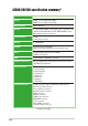
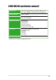
A7N8X-VM/400 specification summary* CPU Socket A for AMD Athlon™ XP 2700MHz+ processors Chipset NVIDIA® nForce2 IGP North bridge NVIDIA® nForce2 MCP South bridge Front Side Bus 400/333/266 MHz Memory 2 x 184-pin DDR DIMM sockets support up to maximum 2 GB unbuffered PC2700/2100 non-ECC DDR SDRAM memory. Dual-channel memory architecture Expansion slots 3 x PCI 1 x AGP 8X (1.
A7N8X-VM/400 specification summary* BIOS features 4Mb Flash ROM, AMI BIOS, ACPI, DMI2.0, WfM2.0, Green, PnP, TCAV, SMBIOS 2.3 ASUS EZ Flash, ASUS MyLogo2 Industry standard PCI 2.2, USB 2.0 Manageability DMI 2.
x
Chapter 1 This chapter describes the features of the motherboard. It includes brief descriptions of the motherboard components, and illustrations of the layout, jumper settings, and connectors.
1.1 Welcome! Thank you for buying the ASUS® A7N8X-VM/400 motherboard! The ASUS A7N8X-VM/400 motherboard comes with the most advanced technologies to deliver maximum performance for Socket A processors. This motherboard is packed with value-added features for guaranteed consumer satisfaction. The following sections provide important technical information about the motherboard for future upgrades or system reconfiguration.
AGP 8X support AGP 8X (AGP 3.0) is the next generation VGA interface specification that enables enhanced graphics performance with high bandwidth speeds of up to 2.12 GB/s. See details on page 1-13. Integrated GeForce4 MX GPU This motherboard is equipped with an integrated GeForce MX GPU, a second-generation mainstream graphics processing unit designed to deliver the best graphics experience with its high texture content and scene complexity capabilities. See details on page 2-13.
1.4 Motherboard components Before you install the motherboard, learn about its major components and available features to facilitate the installation and future upgrades. Refer to the succeeding pages for the component descriptions.
1 Onboard LED. This onboard LED lights up if there is a standby power on the motherboard. This LED acts as a reminder to turn off the system power before plugging or unplugging devices. 2 ATX power connector. This standard 20-pin connector connects to an ATX 12V power supply. The power supply must have at least 1A on the +5V standby lead (+5VSB). 3 CPU socket. This is a Zero Insertion Force (ZIF) socket for AMD Athlon XP™ processors. 4 North bridge controller.
1-6 12 Audio CODEC. The Realtek ALC650 6-channel Audio CODEC is AC’97-compliant onboard audio solution for PC multimedia systems. 13 PCI slots. These 32-bit PCI 2.2 expansion slots support bus master PCI cards like SCSI and LAN cards. 14 LAN controller. The Realtek 8201BL LAN PHY Fast Ethernet controller allows connection to a Local Area Network (LAN) through a network hub. 15 PS/2 mouse port. This green 6-pin connector is for a PS/2 mouse. 16 Parallel port.
1.5 Motherboard layout 24.5cm (9.64in) PS/2 T: Mouse B: Keyboard Socket 462 USBPW34 FLOPPY1 CPU_FAN1 Bottom: Top: USB1 RJ-45 USB2 Top:Line In Center:Line Out Below:Mic In U46 nVidia nForce2 IGP 2 3 4 5 CHA_FAN A7N8X-VM 24.5cm (9.
1.6 Motherboard installation The A7N8X-VM/400 uses the Micro ATX form factor. Unplug the power cord before installing the motherboard. Failure to do so may cause you physical injury and damage Motherboard components. 1.6.1 Placement direction When installing the motherboard, orient the chassis correctly. The edge with the external ports goes to the rear part of the chassis. Refer to the image below.
1.7 Before you proceed Take note of the following precautions before you install motherboard components or change any motherboard settings. 1. Unplug the power cord from the wall socket before touching any component. 2. Use a grounded wrist strap or touch a safely grounded object or to a metal object, such as the power supply case, before handling components to avoid damaging them due to static electricity. 3. Avoid touching the ICs on components. 4.
1.8 Central Processing Unit (CPU) The motherboard provides a Socket A (462) for CPU installation. The A7N8X-VM/400 supports Athlon™ XP processors with “QuantiSpeed” data processing, large data caches, 3D enhancements and 400/333/266MHz bus speeds. AMD Athlon™ XP processors offer gigahertz speeds to support all the latest computing platforms and applications. CPU NOTCH TO INNER CORNER LOCK LEVER A7N8X-VM AMD™ CPU CPU NOTCH A7N8X-VM/400 Socket 462 Each AMD CPU has a “marked” corner.
1.9 System memory The motherboard has two DDR DIMM sockets that supports up to 2GB non-ECC PC2700/2100 DDR SDRAM DIMMs. Each DIMM socket is two-sided. DIMMs come in combinations of single or double-sided types ranging through 64MB, 128MB, 256MB, 512MB and 1GB. The A7N8X-VM/400 motherboard supports the dual-channel memory architecture when you install two DIMMs. 104 Pins A7N8X-VM 80 Pins A7N8X-VM/400 184-Pin DDR DIMM Sockets Installing a DIMM 1.
1.10 Expansion slots The A7N8X-VM/400 motherboard has three (3) PCI and one (1) Accelerated Graphics Port (AGP). The following sub-sections describe the slots and the expansion cards that they support. 1.10.1 Configuring an expansion card Some expansion cards need an IRQ to operate. Generally, an IRQ must be exclusively assigned to one function at a time. In a standard design configuration, 16 IRQs are available but most are already in use. Normally, 6 IRQs are free for expansion cards.
1.10.2 AGP slot This motherboard has an Accelerated Graphics Port (AGP) slot that supports +1.5V AGP 8X cards. Note the notches on the card golden fingers to ensure that they fit the AGP slot on your motherboard. This AGP slot also supports Digital Video Output (DVO) interface cards (AGP-NV-DVI) for digital display on newgeneration LCD monitors and projectors.
1.11 Jumpers This section describes and illustrates the jumpers on the motherboard. 1. USB device wake-up (3-pin USBPW12, USBPW34, USBPW56) Set these jumpers to +5V to wake up the computer from S1 sleep mode (CPU stopped, DRAM refreshed, system running in low power mode) using the connected USB devices. Set to +5VSB to wake up from S3 sleep mode (no power to CPU, DRAM in slow refresh, power supply in reduced power mode).
2. Clear RTC RAM (CLRTC1) This jumper clears the Real Time Clock (RTC) RAM of date, time and system setup parameters in CMOS. The RAM data in CMOS is powered by the onboard button cell battery. To erase the RTC RAM: 1. Turn OFF the computer and unplug the power cord. 2. Remove the battery. 3. Move the jumper caps from [1-2] to [2-3] momentarily. Replace the jumper cap to the original position, [1-2]. 4. Re-install the battery. 5. Plug the power cord and turn ON the computer. 6.
1.12 Connectors This section describes and illustrates the connectors on the motherboard. 1. IDE connectors (40-1 pin PRI_IDE, SEC_IDE) This connector supports the provided UltraDMA133 IDE hard disk ribbon cable. Connect the cable’s blue connector to the primary (recommended) or secondary IDE connector, then connect the gray connector to the UltraDMA133 slave device (hard disk drive) and the black connector to the UltraDMA133 master device.
3. ATX power connectors (20-pin ATXPWR1) These connectors connect to an ATX 12V power supply. The plugs from the power supply are designed to fit these connectors in only one orientation. Find the proper orientation and push down firmly until the connectors fit. ATXPWR1 A7N8X-VM +12.0VDC +5VSB PWR_OK COM +5.0VDC COM +5.0VDC COM +3.3VDC +3.3VDC +5.0VDC +5.0VDC -5.0VDC COM COM COM PS_ON# COM -12.0VDC +3.
5. GAME/MIDI connector (16-1 pin GAME1) This connector supports a GAME/MIDI module. Connect one end of the GAME/MIDI cable to this connector. The GAME/MIDI port on the module connects a joystick or a game pad for playing games, and MIDI devices for playing or editing audio files. +5V J1B2 J1CY GND GND J1CX J1B1 +5V A7N8X-VM MIDI_IN J2B2 J2CY MIDI_OUT J2CX J2B1 +5V GAME1 A7N8X-VM/400 Game Connector The USB/GAME module is purchased separately. 6.
7. Chassis intrusion connector (4-1 pin CHASSIS1) This lead is for a chassis designed with intrusion detection feature. This requires an external detection mechanism such as a chassis intrusion sensor or microswitch. When you remove any chassis component, the sensor triggers and sends a high-level signal to this lead to record a chassis intrusion event. By default, the pins labeled “Chassis Signal” and “Ground” are shorted with a jumper cap.
9. Internal audio connectors (4 pin CD1, AUX1) These connectors allow you to receive stereo audio input from sound sources such as a CD-ROM, TV tuner or MPEG card. AUX1 (White) CD1 (Black) Left Audio Channel A7N8X-VM Ground Right Audio Channel A7N8X-VM/400 Internal Audio Connectors 10. TV out connector (6-1 pin U46) This 6-1 pin connector connects to the front panel daughter card with the audio TV-out port. This connector allows dual display (TV+VGA or TV+DVI) with the ASUS AV/S and AGP-NV-DVI cards.
11. Digital audio connector (6-1 pin SPDIF1) SPDIF_OUT +5V SPDIF_IN GND A7N8X-VM GND This connector is for optional S/PDIF audio module that allows digital instead of analog sound input and output. SPDIF1 1 A7N8X-VM/400 Digital Audio Connector When you input sound for S/PDIF IN, the LINE_OUT will output the sound. Mute LINE_OUT to impede sound output from S/PDIF IN. The S/PDIF module is purchased separately. 12.
13. System panel connector (20-pin PANEL1) This connector accommodates several system front panel functions. PLEDKeylock Ground IDE LED SMI Lead A7N8X-VM/400 Panel Connectors • Reset Ground A7N8X-VM ExtSMI# Ground PWR Ground +5V IDELED PLED+ Power LED Speaker Connector +5V Ground Ground Speaker Keyboard Lock Reset SW ATX Power Switch* * Requires an ATX power supply. System Power LED Lead (3-1 pin PLED) This 3-1 pin connector connects to the system power LED.
Chapter 2 This chapter tells how to change system settings through the BIOS Setup Menus. Detailed descriptions of the BIOS parameters are also provided.
2.1 Managing and updating your BIOS The following utilities allow you to manage and update the motherboard Basic Input/Output System (BIOS) setup. 1. AFUDOS (Updates the BIOS in DOS mode using a bootable floppy disk.) 2. ASUS EZ Flash (Updates the BIOS using a floppy disk during POST.) 3. ASUS Update (Updates the BIOS in Windows® environment. See Chapter 3 for details.) Refer to the corresponding section for each utility.
2.1.2 Using AFUDOS to copy the current BIOS The AFUDOS.EXE utility can also be used to copy the current system BIOS settings to a floppy or hard disk. The copy can be used as a backup in case the system BIOS fails or gets corrupted. 1. At the DOS prompt, type the command line: afudos /o where “filename” can be any user provided filename of not more than eight (8) alpha-numeric characters for the main filename and three (3) alpha-numeric characters for the extension name. Press the Enter key.
2.1.3 Using AFUDOS to update the BIOS Update the BIOS only if you are sure that the new BIOS revision will solve your problems. Careless updating may result to more problems with the motherboard! 1. Download an updated ASUS BIOS file from the Internet (www.asus.com), then save the file to the bootable floppy disk you created earlier. Write down the BIOS file name to a piece of paper. You need to type the exact BIOS file name at the prompt. 2. Copy the AFUDOS.
2.1.4 Using ASUS EZ Flash to update the BIOS The ASUS EZ Flash feature allows you to easily update the BIOS without having to go through the long process of booting from a diskette and using a DOS-based utility. The EZ Flash is built-in the BIOS firmware so it is accessible by simply pressing + during the Power-On Self Tests (POST). To update the BIOS using ASUS EZ Flash: 1. Visit the ASUS website (www.asus.com) to download the latest BIOS file for your motherboard.
2.1.5 ASUS Update The ASUS Update is a utility that allows you to update the motherboard BIOS in Windows® environment. This utility is available in the support CD that comes with the motherboard package. ASUS Update requires an Internet connection either through a network or an Internet Service Provider (ISP). To install ASUS Update: 1. Insert the support CD into the CD-ROM drive. The Drivers menu appears. 2. Click the Utilities tab, then click Install ASUS Update VX.XX.XX.
4. From the FTP site, select the BIOS version that you wish to download. Click Next. 5. Follow the instructions on the succeeding screens to complete the update process. If you selected the option to update the BIOS from a file, a window pops up prompting you to locate the file. Select the file, click Save, then follow the screen instructions to complete the update process.
2.2 BIOS Setup program Use the BIOS Setup program when you are installing a motherboard, reconfiguring your system, or prompted to “Run Setup”. This section explains how to configure your system using this utility. Even if you are not prompted to use the Setup program, you may want to change the configuration of your computer in the future. For example, you may want to enable the security password feature or make changes to the power management settings.
2.2.2 Legend bar At the bottom of the Setup screen is a legend bar. The keys in the legend bar allow you to navigate through the various setup menus. The following table lists the keys found in the legend bar with their corresponding functions.
Sub-menu Note that a right pointer symbol (as shown on the left) appears to the left of certain fields. This pointer indicates that you can display a sub-menu from this field. A sub-menu contains additional options for a field parameter. To display a sub-menu, move the highlight to the field and press . The sub-menu appears. Use the legend keys to enter values and move from field to field within a sub-menu as you would within a menu. Use the key to return to the main menu.
System Date [XX/XX/XXXX] Sets the system to the date that you specify (usually the current date). The format is month, day, year. Valid values for month, day, and year are Month: (1 to 12), Day: (1 to 31), Year: (up to 2099). Use the or + keys to move between the month, day, and year fields. Legacy Diskette A [1.44M, 3.5 in.] Sets the type of floppy drive installed. Configuration options: [Disabled] [360K, 5.25 in.] [1.2M , 5.25 in.] [720K , 3.5 in.] [1.44M, 3.5 in.] [2.88M, 3.5 in.
PIO Mode [Auto] This option lets you set a PIO (Programmed Input/Output) mode for the IDE device. Modes 0 through 4 provide successive increase in performance. Configuration options: [0] [1] [2] [3] [4] Ultra DMA Mode [Auto] This field enables you to select the DMA mode. Configuration options: [Auto] [SWDMA0] [SWDMA1] [SWDMA2] [MWDMA0] [MWDMA1] [MWDMA2] [UDMA0] [UDMA1] [UDMA2] [UDMA3] [UDMA4] SMART Monitoring [Auto] This field allows you to enable or disable the S.M.A.R.T.
2.4 Advanced menu 2.4.1 Chipset Video Frame Buffer Size [ 32MB] This field sets the size of the video frame buffer. The settings on this field is valid only for motherboard models with onboard VGA controller. Configuration options: [Auto] [8MB] [16MB] [32MB] [64MB] [128MB] Graphics Aperture Size [ 64MB] This feature allows you to select the size of mapped memory for AGP graphic data.
MDA Access Control [AGP] This field selects the MDA Access cycles direction. Configuration options: [AGP] [PCI] Primary Video [PCI] This will switch the PCI Bus scanning order while searching for a video card. This allows the user to select the type of Primary VGA in case of multiple video controllers. Configuration options: [PCI] [AGP/Onboard] Onboard TV-out format [PAL] This field allows you to set the onboard TV-out standard. Configuration options: [PAL] [NTSC] 2.4.
Parallel Port Mode [ECP] This field allows the BIOS to select the Parallel Port Mode. Configuration options: [Normal] [EPP] [ECP] [EPP+ECP] ECP Mode DMA Channel [DMA3] This field allows the BIOS to select the Parallel Port ECP DMA. Configuration options: [DMA0] [DMA1] [DMA3] Parallel Port IRQ [IRQ7] This field allows the BIOS to select the Parallel Port IRQ. Configuration options: [IRQ5l] [IRQ7] Onboard Game Port [Disabled] Allows you to select the Game Port address or to disable the port.
2.4.3 PCIPnP Plug and Play O/S [No] This field configures the Plug and Play O/S feature. If set to [No], the BIOS configures all the devices attached to the system. If set to [Yes], the operating system configures Plug and Play (PnP) devices not required for boot if the system has a Plug and Play operating system feature. Configuration options: [No] [Yes] PCI Latency Timer [64] Leave this field to the default setting [64] for best performance and stability.
PCI IDE BusMaster [Enabled] When this option is [Enabled], the BIOS uses the PCI bus mastering to read and write to IDE drives. Configuration options: [Enabled] [Disabled] Offboard PCI/ISA IDE Card [Auto] This field allows the setting of the proper slot of installed PCI IDE cards. Some PCI IDE cards require this to be set to the PCI slot number that is holding the card.
2.5 Power menu The Power menu allows you to reduce power consumption. This feature turns off the video display and shuts down the hard disk after a period of inactivity. Suspend Mode [S1 & S3 (STR)] This field allows the BIOS to select the ACPI state used for System Suspend . Configuration options: [S1 & S3 (STR)] [S1 (POS) only] 2.5.1 Power Up Control Restore on AC Power Loss [Power Off] When set to Power Off, the system goes into off state after an AC power loss.
Resume on Keyboard [Disabled] This parameter allows you to use the keyboard keys to turn on the system. This feature requires an ATX power supply that provides at least 1A on the +5VSB lead. Configuration options: [Disabled] [Enabled] Resume on PS/2 Mouse [Disabled] This parameter allows you to use the PS/2 mouse to turn on the system. This feature requires an ATX power supply that provides at least 1A on the +5VSB lead.
2.5.2 Hardware Monitor MB Temperature [xxxC/xxxF] CPU Temperature [xxxC/xxxF] The onboard hardware monitor automatically detects and displays the motherboard, CPU, and power temperatures CPU Fan Speed [xxxxRPM] or [Disabled] Chassis Fan Speed [xxxxRPM] or [Disabled] The onboard hardware monitor automatically detects and displays the CPU, chassis, and power fan speeds in rotations per minute (RPM). If any of the fans is not connected to the motherboard, that field shows 0RPM. VCORE Voltage, 3.
2.6 Boot menu 1st, 2nd, 3rd Boot Device This field specifies the boot sequence from the available devices. Additional plug-in boot devices installed appear in sequence after the list of current boot devices . Configuration fields include FLOPPY DRIVE, IDE Hard Drive, ATAPI CD-ROM, and Other Boot Device. 2.6.1 Boot Settings Configuration Quick Boot [Enabled] This field allows BIOS to skip certain tests while booting. This will decrease the time needed to boot the system.
Full Screen Logo [Enabled] When [Enabled], MyLogo is displayed instead of the POST messages. Setting to [Disabled] displays the normal POST messages. Configuration options: [Disabled] [Enabled] Make sure that the above item is set to [Enabled] if you wish to use the ASUS MyLogo2 feature. See MyLogo2 details on page 3-8. AddOn ROM Display Mode [Force BIOS] This field sets the display mode for option ROM.
2.6.2 Security The Security menu items allow you to change the system security settings. Select an item then press Enter to display the configuration options. Security Settings Supervisor Password User Password Not Installed Not Installed to change password. again to disable password. Change Supervisor Password Clear User Password Change Supervisor Password Select this item to set or change the supervisor password.
Security Settings Supervisor Password User Password Change Supervisor Password User Access Level Clear User Password Password Check to change password. again to disable password. Not Installed Not Installed [Full Access] [Setup] User Access Level (Full Access] This item allows you to select the access restriction to the Setup items. Configuration options: [No Access] [View Only] [Limited] [Full Access] No Access prevents user access to the Setup utility.
2.7 Exit menu When you have made all of your selections from the various menus in the Setup program, save your changes and exit Setup. Select Exit from the menu bar to display the following menu. Exit Options Exit & Save Changes Exit & Discard Changes Discard Changes Exit system setup after saving the changes. F10 key can be used for this operation. Load Setup Defaults Pressing does not immediately exit this menu. Select one of the options from this menu or from the legend bar to exit.
Load Setup Defaults This option allows you to load the default values for each of the parameters on the Setup menus. When you select this option or if you press , a confirmation window appears. Select [Yes] to load default values. Select Exit Saving Changes or make other changes before saving the values to the non-volatile RAM.
Chapter 3 This chapter describes the contents of the support CD that comes with the motherboard package.
3.1 Installing an operating system This motherboard supports Windows® 98SE/ME/NT/2000/XP as well as Linux Red Hat, SuSE, TurboLinux and Caldera operating systems (OS). Always install the latest OS version and corresponding updates so you can maximize the features of your hardware. Because motherboard settings and hardware options vary, use the setup procedures presented in this chapter for general reference only. Refer to your OS documentation for more information. 3.
3.2.2 Drivers menu The drivers menu shows the available device drivers if the system detects installed devices. Install the necessary drivers to activate the devices. Screen display and driver options may not be the same for other operating system versions. NVIDIA Display Driver This item installs the NVIDIA display driver for the onboard VGA. NVIDIA nForce Driver This item installs the driver for the NVIDIA nForce chipset. USB 2.0 Driver This item installs the USB 2.0 driver.
3.2.3 Utilities The Utilities tab displays the applications that the motherboard supports. ASUS PC Probe This convenient utility continuously monitors your computer systems vital components such as fan rotations, CPU temperature, and system voltages, and alerts you on any detected problems. This utility helps you keep your computer at a healthy operating condition. Install ASUS Update This program allows you to download the latest version of the BIOS from the ASUS website.
3.2.4 ASUS contact information Click the Contact tab to display the ASUS contact information.
3-6 Chapter 3: Software support