
User Guide


1-14
Chapter 1: Motherboard Information
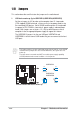
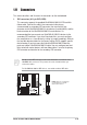
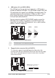
3. ATX power connectors (20-pin ATXPWR1)
These connectors connect to an ATX 12V power supply. The plugs from the
power supply are designed to fit these connectors in only one orientation. Find
the proper orientation and push down firmly until the connectors completely fit.
If you will need to replace the power supply in the future, make sure that your
new ATX 12V power supply can provide 8A on the +12V lead and at least 1A on
the +5-volt standby lead (+5VSB). The minimum recommended wattage is
230W, or 300W for a fully configured system. The system may become unstable
and may experience difficulty powering up if the power supply is inadequate.
A7S266-VM/U2
®
A7S266-VM/U2 ATX Power Connector
+3.3VDC
-12.0VD
C
COM
PS_ON#
COM
COM
COM
-5.0VDC
+5.0VDC
+5.0VDC
PWR_OK
+12.0VDC
+3.3VDC
+3.3VDC
COM
+5.0VDC
COM
+5.0VDC
COM
+5VSB
ATXPWR1
Do not forget to connect the fan cables to the fan connectors. Lack of sufficient
air flow within the system may damage the motherboard components. These
are not jumpers! DO NOT place jumper caps on the fan connectors!
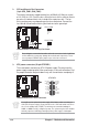
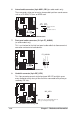
2. CPU and Chassis Fan Connectors
(3-pin CPU_FAN1, CHA_FAN1)
The two fan connectors support cooling fans of 350mA (4.2 Watts) or a total
of 1A (12W) at +12V. Orient the fans so that the heat sink fins allow air flow to
go across the onboard heat sinks instead of the expansion slots. The fan
wiring and plug may vary depending on the fan manufacturer. Connect the
fan cable to the connector matching the black wire to the ground pin.
A7S266-VM/U2
®
A7S266-VM/U2 12-Volt Cooling Fan Power
CPU_FAN
1
GND
Rotation
+12V
CHA_FAN
1
GND
Rotation
+12V