
Quick start manual

A7V-VM User’s Manual 7
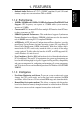
2. HARDWARE SETUP
2. H/W SETUP
System Memory
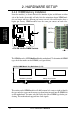
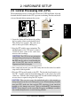
2.4 System Memory (DIMM)
NOTE: No hardware or BIOS setup is required after adding or removing memory.
This motherboard uses only Dual Inline Memory Modules (DIMMs). Sockets are
available for 3.3Volt (power level) unbuffered Synchronous Dynamic Random Ac-
cess Memory (SDRAM) of 16, 32, 64, 128MB, 256 or 512MB to form a memory size
between 16MB and 1GB. One side (with memory chips) of the DIMM takes up one
row on the motherboard.
To use the chipset’s Error Checking and Correction (ECC) feature, you must use a
DIMM with 9 chips per side (standard 8 chips/side + 1 ECC chip).
Install memory in any combination as follows:
Location 168-pin DIMM Total Memory
DIMM1 (Rows 0&1) SDRAM 16, 32, 64, 128, 256, 512MB x1
DIMM2 (Rows 2&3) SDRAM 16, 32, 64, 128, 256, 512MB x1
Total System Memory (Max 1GB) =
2.5.1 General DIMM Notes
• This motherboard supports SPD (Serial Presence Detect) DIMMs. This is the
memory of choice for best performance vs. stability.
• This motherboard does NOT support registered memory.
• SDRAM chips are generally thinner with higher pin density than EDO (Ex-
tended Data Output) chips.
• Single-sided DIMMs come in 16, 32, 64,128, 256MB; double-sided come in 32,
64, 128, 256, 512MB.
• For optimum signal integrity, inserting the DIMMs in the following order is
recommended: DIMM1, DIMM2.
• SDRAMs used must be compatible with the current PC133/PC100 SDRAM
specification.
IMPORTANT