User Guide Motherboard A7V8X-X
E1198 Checklist First Edition V1 January 2003 Copyright © 2003 ASUSTeK COMPUTER INC. All Rights Reserved. No part of this manual, including the products and software described in it, may be reproduced, transmitted, transcribed, stored in a retrieval system, or translated into any language in any form or by any means, except documentation kept by the purchaser for backup purposes, without the express written permission of ASUSTeK COMPUTER INC. (“ASUS”).
Contents Features Notices ............................................................................................ v Safety information .......................................................................... vi About this guide ............................................................................. vii ASUS contact information ............................................................ viii A7V8X-X specifications summary ..................................................
Contents Safeguards 2.3 2.4 2.5 2.6 2.7 Main Menu ........................................................................ 2-10 2.3.1 Primary and Secondary Master/Slave ................. 2-12 2.3.2 Keyboard Features .............................................. 2-14 Advanced Menu ............................................................... 2-15 2.4.1 Chip Configuration ............................................... 2-16 2.4.2 I/O Device Configuration ...................................... 2-18 2.
Notices Federal Communications Commission Statement This device complies with FCC Rules Part 15. Operation is subject to the following two conditions: • This device may not cause harmful interference, and • This device must accept any interference received including interference that may cause undesired operation. This equipment has been tested and found to comply with the limits for a Class B digital device, pursuant to Part 15 of the FCC Rules.
Safety information Electrical safety • To prevent electrical shock hazard, disconnect the power cable from the electrical outlet before relocating the system. • When adding or removing devices to or from the system, ensure that the power cables for the devices are unplugged before the signal cables are connected. If possible, disconnect all power cables from the existing system before you add a device.
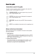
About this guide Conventions used in this guide To make sure that you perform certain tasks properly, take note of the following symbols used throughout this manual. WARNING/DANGER: Information to prevent injury to yourself when trying to complete a task. CAUTION: Information to prevent damage to the components when trying to complete a task. IMPORTANT: Information that you MUST follow to complete a task. NOTE: Tips and additional information to aid in completing a task.
ASUS contact information ASUSTeK COMPUTER INC. (Asia-Pacific) Address: General Tel: General Fax: General Email: 150 Li-Te Road, Peitou, Taipei, Taiwan 112 +886-2-2894-3447 +886-2-2894-3449 info@asus.com.tw Technical Support MB/Others (Tel): Notebook (Tel): Desktop/Server (Tel): Support Fax: Support Email: Web Site: +886-2-2890-7121 (English) +886-2-2890-7122 (English) +886-2-2890-7123 (English) +886-2-2890-7698 tsd@asus.com.tw www.asus.com.
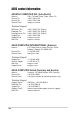
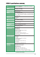
A7V8X-X specifications summary CPU Socket A for AMD Barton/Thoroughbred/Athlon XP/Athlon/ Duron 2.25+ GHz CPU Chipset Northbridge: VIA KT400 Southbridge: VIA VT8235 Front Side Bus (FSB) 200/266/333Mhz Memory 3 x DDR DIMM Sockets Max. 3 GB unbuffered PC2100/1600 non-ECC DDR SDRAM (Note: PC3200 maximum to 2 banks only. PC2700 maximum to 4 banks only.
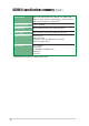
A7V8X-X specifications summary (Cont’) BIOS features 2Mb Flash ROM, Award BIOS, DMI2.0, PnP, WfM2.0, SM BIOS 2.3, TCAV, EZ Flash, ASUS MyLogo, ASUS CrashFree BIOS, ASUS JumperFree, ASUS C.P.R. Industry standard PCI 2.2, USB 2.0 Manageability WfM2.0, DMI2.0, WOR, WOL, Chassis Intrusion Form Factor ATX form factor: 12 in x 9.6 in (30.5 cm x 24.
This chapter gives information about the ASUS A7V8X-X motherboard that came with the system.This chapter includes the motherboard layout, jumper settings, and connector locations.
1.1 Welcome! Thank you for buying the ASUS® A7V8X-X motherboard! The ASUS A7V8X-X motherboard is loaded with the most advanced technologies to deliver the maximum performance for socket A processors. This motherboard is loaded with value-added features for guaranteed consumer satisfaction. Unique ASUS features such as ASUS C.O.P., ASUS C.P.R., ASUS EZFlash, ASUS JumperFree, ASUS MyLogo, ASUS CrashFree BIOS and more are included to ensure the best user experience and value in a motherboard.
1.3 Motherboard components Before you install the motherboard, learn about its major components and available features to facilitate the installation and future upgrades. Refer to the succeeding pages for the component descriptions.
1.3.1 Core specifications 1 North bridge controller. The VIA® KT400 supports AGP 8X mode, 333/ 266/200MHz Front Side Bus, and the latest 400/333/266/200MHz 64-bit memory bus. 2 CPU socket. Socket 462 (Socket A) surface mount, Zero Insertion Force (ZIF) socket for the AMD Barton/Thoroughbred/Athlon XP/Athlon/Duron Processors, with 600 MHz ~ 2.25GHz system bus. (Note: When using 333MHz FSB CPU, system memory supports DDR333 only.) TABLE 1.3.
12 Audio CODEC . The ADI AD1980 is an AC’97 CODEC that allows 6-channel audio playback. The audio CODEC provides six DAC channels for 5.1 surround sound, S/PDIF interface, AUX and Line In stereo inputs, integrated headphone amplifier, greater than 90dB dynamic range. (on audio models only) 13 LAN PHY. This Realtek RTL8201BL LAN PHY supports your local area networking needs. (on LAN model only) 14 AGP slot. This Accelerated Graphics Port (AGP) slot supports 1.
1.4 Special features 1.4.1 Product highlights 333MHz FSB Athlon XP CPU support AMD’s Athlon XP 2800+ and all follow-up CPUs now support 333MHz Front Side Bus (FSB) for increased application program productivity and enhanced digital media experience. AGP 8X support AGP 8X (AGP 3.0) is the next generation VGA interface specification that enables enhanced graphics performance with high bandwidth speeds up to 2.12 GB/s. With a bus of 533Mhz, AGP 8X is twice as fast as AGP 4X.
1.5 Motherboard layout 24.4cm (9.6in) PS/2KBMS T: Mouse B: Keyboard CPU_FAN OVER_VOLT 2 3 4 5 USBPW12 USBPW34 VIA KT400 Top: USB3 RJ-45 USB4 AUX CD Accelerated Graphics Port (AGP) LAN PHY FLOPPY Chipset Top:Line In Center:Line Out Below:Mic In SEC_IDE Bottom: PRI_IDE USB20_12 30.5cm (12.
1.6 Before you proceed Take note of the following precautions before you install motherboard components or change any motherboard settings. 1. Unplug the power cord from the wall socket before touching any component. 2. Use a grounded wrist strap or touch a safely grounded object or to a metal object, such as the power supply case, before handling components to avoid damaging them due to static electricity. 3. Hold components by the edges to avoid touching the ICs on them. 4.
1.7 Motherboard installation Before you install the motherboard, study the configuration of your chassis to ensure that the motherboard fits into it. The motherboard uses the ATX form factor that measures 12 inches x 9.6 inches (30.5 cm x 24.5 cm). Make sure to unplug the power cord before installing or removing the motherboard. Failure to do so may cause you physical injury and damage motherboard components. 1.7.
1.8 Central Processing Unit (CPU) The motherboard provides a Socket A (462) for CPU installation. AMD processors offer gigahertz speeds to support all the latest computing platforms and applications. The A7V8X-X supports AthlonTM XP, AthlonTM, Barton™ and DuronTM processors. CPU NOTCH TO INNER CORNER AMD™ CPU A7V8X-X ® A7V8X-X Socket A 1.8.1 CPU NOTCH LEVER LOCK Installing the CPU Follow these steps to install a CPU: 1.
1.9 System memory The motherboard has three Double Data Rate (DDR) DIMM sockets that supports up to 3GB unbuffered non-ECC PC3200/2700/2100/1600 DDR DIMMs. A DDR DIMM has the same physical dimensions as an SDR DIMM, but it has a 184-pin footprint compared to the 168-pin of the SDR DIMM. Also, a DDR DIMM is single notched while an SDR DIMM is double notched. 104 Pins A7V8X-X 80 Pins ® A7V8X-X 184-Pin DDR DIMM Sockets A DDR or SDR DIMM is keyed with a notch so that it fits in only one direction.
1.10.
1.11 Jumpers This section describes and illustrates the jumpers on the motherboard. 1. USB device wake-up (3-pin USBPWR12,USBPWR34,USBPWR56) Set these jumpers to +5V to wake up the computer from S1 sleep mode (CPU stopped, DRAM refreshed, system running in low power mode) using the connected USB devices. Set to +5VSB to wake up from S3 sleep mode (no power to CPU, DRAM in slow refresh, power supply in reduced power mode).
3. Clear RTC RAM (CLRTC) These jumpers allow you to clear the Real Time Clock (RTC) RAM in CMOS. You can clear the CMOS memory of date, time, and system setup parameters by erasing the CMOS RTC RAM data. The RAM data in CMOS is powered by the onboard button cell battery. To erase the RTC RAM: 1. Turn OFF the computer and unplug the power cord. 2. Remove the battery. 3. Short the jumper by placing the jumper cap to pins [1-2] and replace it to pins [2-3] after 3 seconds. 4. Re-install the battery. 5.
1.12 Connectors This section describes and illustrates the connectors on the motherboard. 1. ATX power connectors (20-pin ATXPWR) These connectors connect to an ATX 12V power supply. The plugs from the power supply are designed to fit these connectors in only one orientation. Find the proper orientation and push down firmly until the connectors completely fit. ATXPWR A7V8X-X ® +3.3VDC -12.0VDC COM PS_ON# COM COM COM -5.0VDC +5.0VDC +5.0VDC +3.3VDC +3.3VDC COM +5.0VDC COM +5.0VDC COM PWR_OK +5VSB +12.
3. IDE connectors (40-1 pin PRI_IDE, SEC_IDE) This connector supports the provided UltraDMA/133/100/66 IDE hard disk ribbon cable. Connect the cable’s blue connector to the primary (recommended) or secondary IDE connector, then connect the gray connector to the UltraDMA/133/100/66 slave device (hard disk drive) and the black connector to the UltraDMA/133/100/66 master device. It is recommended that you connect non-UltraDMA/133/100/66 devices to the secondary IDE connector.
5. Floppy disk drive connector (34-1 pin FLOPPY) This connector supports the provided floppy drive ribbon cable. After connecting one end to the motherboard, connect the other end to the floppy drive. (Pin 5 is removed to prevent incorrect insertion when using ribbon cables with pin 5 plug). FLOPPY A7V8X-X PIN 1 ® NOTE: Orient the red markings on the floppy ribbon cable to PIN 1. A7V8X-X Floppy Disk Drive Connector 6.
7. Internal audio connectors (4-pin AUX, CD) These connectors allow you to receive stereo audio input from sound sources such as a CD-ROM, TV tuner, or MPEG card. AUX (White) CD (Black) Left Audio Channel Ground Ground Right Audio Channel A7V8X-X ® A7V8X-X Internal Audio Connectors 8. Front panel audio connectors (10-1 pin FP_AUDIO) BLINE_OUT_L AGND +5VA BLINE_OUT_R This is an interface for the Intel front panel audio cable that allow convenient connection and control of audio devices.
10. Chassis intrusion connector (4-1 pin CHASSIS) This lead is for a chassis designed with intrusion detection feature. This requires an external detection mechanism such as a chassis intrusion sensor or microswitch. When you remove any chassis component, the sensor triggers and sends a high-level signal to this lead to record a chassis intrusion event. By default, the pins labeled “Chassis Signal” and “Ground” are shorted with a jumper cap.
12. System panel connector (20-pin PANEL) This connector accommodates several system front panel functions. Speaker Connector +5V Ground Ground Speaker PLED- IDE_LED ® SMI Lead A7V8X-X System Panel Connectors Reset Ground A7V8X-X ExtSMI# Ground PWR Ground IDE_LED+ IDE_LED- PLED+ Power LED Reset SW ATX Power Switch* * Requires an ATX power supply. • System Power LED Lead (3-1 pin PLED) This 3-1 pin connector connects to the system power LED.
This chapter gives information about the ASUS A7V8X-X Binary Input/Output System (BIOS).This chapter includes updating the BIOS using the ASUS AFLASH BIOS that is bundled with the support CD.
2.1 Managing and Updating your BIOS It is recommended that you save a copy of the motherboard’s original BIOS to a bootable floppy disk in case you need to reinstall the original BIOS later. 2.1.1 Using ASUS EZ Flash to update the BIOS The ASUS EZ Flash feature allows you to easily update the BIOS without having to go through the long process of booting from a diskette and using a DOS-based utility.
5. At the prompt, “Please Enter File Name for NEW BIOS: _”, type in the BIOS file name that you downloaded from the ASUS website, then press . EZ Flash will automatically access drive A to look for the file name that you typed. When found, the following message appears on screen. If you accidentally typed in a wrong BIOS file name, the error message, “WARNING! File not found.” appears. Press to remove the message, then type in the correct file name. Press . 6.
The BIOS information in the above screen is for reference only. What you see on your screen may not be exactly the same as shown. 2.1.2 Using AFLASH to update the BIOS Creating a bootable disk AFLASH.EXE is a Flash Memory Writer utility that updates the BIOS by uploading a new BIOS file to the programmable flash ROM on the motherboard. This file works only in DOS mode.
5. Select 1. Save Current BIOS to File from the Main menu and press . The Save Current BIOS To File screen appears. 6. Type a filename and the path, for example, A:\XXX-XX.XXX, then press . Updating the BIOS Update the BIOS only if you are sure that the new BIOS revision will solve your problems. Careless updating may result to more problems with the motherboard! 1.
6. When prompted to confirm the BIOS update, press Y to start the update. 7. The utility starts to program the new BIOS information into the Flash ROM. The boot block is updated automatically only when necessary. When the programming is done, the message “Flashed Successfully” appears. 8. Follow the onscreen instructions to continue. DO NOT turn off the system while updating the BIOS. This may cause boot problems.
2.1.3 CrashFree BIOS feature The CrashFree BIOS feature allows you to boot the computer from a floppy disk and update the BIOS in case the original BIOS fails or gets corrupted. 1. You must have a bootable floppy disk ready before updating the BIOS. 2. The bootable floppy disk could be the one that you created following the procedure in section 2.1.2, and should contain the AFLASH.EXE utility. 3. If the BIOS fails (ROM data or codes are corrupted), a message appears during POST indicating the failure.
2.2 BIOS Setup program Use the BIOS Setup program when you are installing a motherboard, reconfiguring your system, or prompted to “Run Setup”. This section explains how to configure your system using this utility. Even if you are not prompted to use the Setup program, you may want to change the configuration of your computer in the future. For example, you may want to enable the security password feature or make changes to the power management settings.
2.2.2 Legend bar At the bottom of the Setup screen is a legend bar. The keys in the legend bar allow you to navigate through the various setup menus. The following table lists the keys found in the legend bar with their corresponding functions.
Sub-menu Note that a right pointer symbol (as shown on the left) appears to the left of certain fields. This pointer indicates that you can display a sub-menu from this field. A sub-menu contains additional options for a field parameter. To display a sub-menu, move the highlight to the field and press . The sub-menu appears. Use the legend keys to enter values and move from field to field within a sub-menu as you would within a menu. Use the key to return to the main menu.
System Date [XX/XX/XXXX] Sets the system to the date that you specify (usually the current date). The format is month, day, year. Valid values for month, day, and year are Month: (1 to 12), Day: (1 to 31), Year: (up to 2099). Use the or + keys to move between the month, day, and year fields. Legacy Diskette A, B [1.44M, 3.5 in.] Sets the type of floppy drive installed. Configuration options: [None] [360K, 5.25 in.] [1.2M , 5.25 in.] [720K , 3.5 in.] [1.44M, 3.5 in.] [2.88M, 3.5 in.
Halt On [All Errors] This field specifies the types of errors that will cause the system to halt. Configuration options: [All Errors] [No Error] [All but Keyboard] [All but Disk] [All but Disk/Keyboard] Installed Memory [XXX MB] This field automatically displays the amount of conventional memory detected by the system during the boot process. 2.3.1 Primary and Secondary Master/Slave Type [Auto] Select [Auto] to automatically detect an IDE hard disk drive.
If no drive is installed or if you are removing a drive and not replacing it, select [None]. Other options for the Type field are: [CD-ROM] - for IDE CD-ROM drives [LS-120] - for LS-120 compatible floppy disk drives [ZIP] - for ZIP-compatible disk drives [MO] - for IDE magneto optical disk drives [Other ATAPI Device] - for IDE devices not listed here After making your selections on this sub-menu, press the key to return to the Main menu.
Maximum LBA Capacity This field shows the drive’s maximum LBA capacity as calculated by the BIOS based on the drive information you entered. Multi-Sector Transfers [Maximum] This option automatically sets the number of sectors per block to the highest number that the drive supports. Note that when this field is automatically configured, the set value may not always be the fastest value for the drive. You may also manually configure this field.
Keyboard Auto-Repeat Rate [12/Sec] This controls the speed at which the system registers repeated keystrokes. Options range from 6 to 30 characters per second. Configuration options: [6/Sec] [8/Sec] [10/Sec] [12/Sec] [15/Sec] [20/Sec] [24/Sec] [30/Sec] Keyboard Auto-Repeat Delay [1/4 Sec] This field sets the time interval for displaying the first and second characters. Configuration options: [1/4 Sec] [1/2 Sec] [3/4 Sec] [1 Sec] 2.
CPU VCore When the CPU VCore Setting parameter above is set to [Manual], the CPU VCore item allows you to select a specific CPU core voltage. This field is not accessible when the CPU VCore Setting is set to [Auto]. CPU Level 1 Cache, CPU Level 2 Cache [Enabled] These fields allow you to choose from the default [Enabled] or choose [Disabled] to turn on or off the CPU Level 1 and Level 2 built-in cache.
SDRAM Configuration [By SPD] This parameter allows you to set the optimal timings for items 2–5, depending on the memory modules that you are using. The default setting is [By SPD], which configures items 2–5 by reading the contents in the SPD (Serial Presence Detect) device. The EEPROM on the memory module stores critical information about the module, such as memory type, size, speed, voltage interface, and module banks.
AGP Drive Strength [Auto] Configuration options: [Auto] [Manual] AGP Drive N Control [E] Configuration options: [0][1][2][3][4][5][6][7][8][9][A][B][C][D][E][F] AGP Drive P Control [F] Configuration options: [0][1][2][3][4][5][6][7][8][9][A][B][C][D][E][F] AGP performance control [Disabled] Configuration options: [Disabled] [Enabled] AGP Fast Write control [Disabled] Configuration options: [Disabled] [Enabled] Video Memory Cache Mode [UC] USWC (uncacheable, speculative write combining) is a new cache t
2.4.2 I/O Device Configuration Onboard FDC Swap A & B [No Swap] These fields set option to switch drive letter assignments. Configuration Options: [No Swap] [Swap AB] Floppy Disk Access Control [R/W] When set to [Read Only], this parameter protects files from being copied to floppy disks by allowing reads from, but not writes to, the floppy disk drive. The default setting [R/W] allows both reads and writes.
Onboard AC97 Audio Controller [Auto] These fields allow you to enable or disable the onboard AC97 audio controller. Configuration options: [Auto] [Disabled] Onboard LAN [Enabled] This field allows you to enable or disable the onboard LAN Boot ROM. Configuration options: [Disabled] [Enabled] Onboard Game Port [200H-207H] These fields allow you to set the addresses for the onboard game connectors. Game ports must have different addresses.
Primary VGA BIOS [PCI VGA Card] This field allows you to select the primary graphics card. Configuration options: [PCI VGA Card] [AGP VGA Card] Onboard LAN Boot ROM [Disabled] This field allows you to enable or disable the onboard LAN Boot ROM. Configuration options: [Disabled] [Enabled] 2.4.3.1 PCI IRQ Resource Exclusion IRQ XX Reserved [No/ICU] These fields indicate whether or not the displayed IRQ for each field is being used by a legacy device.
Power Management [User Defined] This field allows you to activate or deactivate the automatic power saving features. When set to [Disabled], the power management features do not function regardless of the other settings on this menu. The [User Defined] option allows you to set the period of inactivity before the system enters suspend mode. Refer to “Suspend Mode” later in this section. When set to [Max Saving], system power is conserved to its greatest amount.
Suspend Mode [Disabled] Sets the time period before the system goes into suspend mode. Configuration options: [Disabled] [1~2 Min] [2~3 Min] [4~5 min] [8~9 Min] [20 Min] [30 Min] PWR Button < 4 Secs [Soft Off] When set to [Soft off], the ATX switch can be used as a normal system power-off button when pressed for less than 4 seconds. [Suspend] allows the button to have a dual function where pressing less than 4 seconds puts the system in sleep mode.
Power On By PS/2 Mouse [Disabled] When set to [Double Click], this parameter allows you to use the PS/2 mouse to turn on the system. This feature requires an ATX power supply that provides at least 1A on the +5VSB lead. Configuration options: [Disabled] [Double Click] Power Up On PCI Card [Disabled] When set to [Enabled], this parameter allows you to turn on the system through a PCI LAN or modem card. This feature requires an ATX power supply that provides at least 1A on the +5VSB lead.
2.6 Boot Menu Boot Sequence The Boot menu allows you to select four types of boot devices using the up and down arrow keys. By using the <+> or key, you can promote devices and by using the <-> key, you can demote devices. Promotion or demotion of devices alters the priority which the system uses to boot device on system power up. Configuration fields include Removable Devices, IDE Hard Drive, ATAPI CD-ROM, and Other Boot Device.
Reset Configuration Data [No] The Extended System Configuration Data (ESCD) contain information about nonPnP devices. It also holds the complete record of how the system was configured the last time it was booted. Select [Yes] if you want to clear these data during the Power-On-Self-Test (POST). Configuration options: [No] [Yes] Boot Virus Detection [Enabled] This field allows you to set boot virus detection, ensuring a virus-free boot sector.
Pressing does not immediately exit this menu. Select one of the options from this menu or from the legend bar to exit. Exit Saving Changes Once you are finished making your selections, choose this option from the Exit menu to ensure the values you selected are saved to the CMOS RAM. The CMOS RAM is sustained by an onboard backup battery and stays on even when the PC is turned off. When you select this option, a confirmation window appears. Select [Yes] to save changes and exit.
2-28 Chapter 2: BIOS Information
Chapter 3 Starting Up This chapter helps you power up your system and install drivers and utilities that came with the support CD.
3.1 Install an operating system The A7V8X-X motherboard supports Windows ME/NT/2000/XP operating systems (OS). Always install the latest OS version and corresponding updates so you can maximize the features of your hardware. Because motherboard settings and hardware options vary, use the setup procedures presented in this chapter for general reference only. Refer to your OS documentation for more information. 3.
3.2.2 Drivers menu VIA 4 in 1 Driver The item installs the following drivers: - VIA Registry (INF) driver - VIA AGP VxD driver - VIA ATAPI vendor support driver - VIA PCI IRQ Miniport driver AD1980 SoundMAX Audio Driver This item installs the AD1980 SoundMAX audio driver and applications. Install VIA LAN Driver Click this item to load the installation wizard and install the VIA Local Area Network (LAN) driver. USB 2.0 Driver This item installs the USB 2.0 driver.
PC-cillin 2002 This item installs the PC-cillin 2002 V9.02 anti-virus software. ADOBE Acrobat Reader V5.0 This installs software for viewing files in Portable Document Format (PDF). ASUS Screen Saver This item installs the ASUS screen saver. E-Color 3Deep This item installs application to optimize 3D graphics output. 3.2.4 ASUS Contact Information Clicking the ASUS Contact Information tab displays as stated. You may also find this information on page viii of this user guide. 3.2.
1. From the taskbar, double-click on the SoundMAX Digital Integrated Audio icon to display the SoundMAX Sound MAX Digital Integrated Audio icon Control Panel. 2. The Listening Environment screen allows you to set to multi-channel speakers, enable or disable the Virtual Theater Surround, and select Acoustic Environments and Virtual Ear. 3. The default setting is Stereo Speakers (2-channel). To set to a 6channel speaker system, click the arrow under Speaker Setup to display a list of options. 4.
11. Click the arrow under Synthesizer Default Set to display a list of options. Choose your desired setting. 12. Click Apply, then click OK when done. Adjusting the volume settings 1. After rebooting the system, click on the volume control icon on the taskbar (lower right corner of your desktop) to display the Volume Control panel. Volume control icon 2. If you installed an S/PDIF module, click on the Volume Control Advanced button from the Volume Control panel.