使用手冊 Motherboard A88XM-E
T9125 第一版 2014 年 3 月發行 版權說明 ©ASUSTeK Computer Inc. All rights reserved.
目錄內容 安全性須知........................................................................................................................................ iv 關於這本使用手冊............................................................................................................................v 包裝內容物.......................................................................................................................................vii A88XM-E 規格列表........................................................................
安全性須知 電氣方面的安全性 • 為避免可能的電擊造成嚴重損害,在搬動電腦主機之前,請先將電腦電源線暫時 從電源插槽中拔掉。 • 當您要加入硬體裝置到系統中或者要移除系統中的硬體裝置時,請務必先連接該 裝置的排線,然後再連接電源線。可能的話,在安裝硬體裝置之前先拔掉電腦的 電源供應器電源線。 • 當您要從主機板連接或拔除任何的排線之前,請確定所有的電源線已事先拔掉。 • 在使用介面卡或擴充卡之前,我們建議您可以先尋求專業人士的協助。這些裝置 有可能會干擾接地的迴路。 • 請確定電源供應器的電壓設定已調整到本國/本區域所使用的電壓標準值。若您不 確定您所屬區域的供應電壓值為何,那麼請就近詢問當地的電力公司人員。 • 如果電源供應器已損壞,請不要嘗試自行修復。請將之交給專業技術服務人員或 經銷處理。 操作方面的安全性 • 在您安裝主機板以及加入硬體裝置之前,請務必詳加閱讀本手冊所提供的相關資 訊。 • 在使用產品之前,請確定所有的排線、電源線都已正確地連接好。若您發現有任 何重大的瑕疵,請儘速連絡您的經銷商。 • 為避免發生電氣短路情形,請務必將所有沒用到的螺絲、迴紋針及其他零件收 好,不要遺
關於這本使用手冊 產品使用手冊包含了所有當您在安裝華碩 A88XM-E 主機板時所需用到的資訊。 使用手冊的編排方式 使用手冊是由下面幾個章節所組成: • 第一章:產品介紹 您可以在本章節中發現諸多華碩所賦予 A88XM-E 主機板的優異特色。利用簡 潔易懂的說明讓您能很快地掌握 A88XM-E 主機板的各項特性,當然,在本章節 中我們也會提及所有能夠應用在 A88XM-E 的新產品技術。 • 第二章:BIOS 資訊 本章節描述如何使用 BIOS 設定程式中的每一個選單項目來更改系統的組態設 定。此外也會詳加介紹 BIOS 各項設定值的使用時機與參數設定。 提示符號 為了能夠確保您正確地完成主機板設定,請務必注意下面這些會在本手冊中出現 的標示符號所代表的特殊含意。 警告:提醒您在進行某一項工作時要注意您本身的安全。 小心:提醒您在進行某一項工作時要注意勿傷害到電腦主機板元件。 重要: 此符號表示您必須要遵照手冊所描述之方式完成一項或多項軟硬體的安 裝或設定。 注意:提供有助於完成某項工作的訣竅與其他額外的資訊。 v
哪裡可以找到更多的產品資訊 您可以經由下面所提供的兩個管道來獲得您所使用的華碩產品資訊以及軟硬體的 更新資訊等。 1. 華碩網站 您可以到 http://tw.asus.com 華碩電腦全球資訊網站取得所有關於華碩軟硬體產品 的各項資訊。 2. 其他檔案 在您的產品包裝盒中除了本手冊所列舉的標準配件之外,也有可能會夾帶有其他 的檔案,譬如經銷商所附的產品保證單據等。 代理商查詢 華碩主機板在台灣透過聯強國際與精技電腦兩家代理商出貨,您請參考下列範例 圖示找出產品的 12 碼式序號標籤(下圖僅供參考),再至 http://tw.asus.com/support/ eService/querydist_tw.
包裝內容物 在您拿到本主機板包裝盒之後,請馬上檢查下面所列出的各項標準配件是否齊全。 主機板 華碩 A88XM-E 主機板 排線 2 x Serial ATA 6.0Gb/s 排線 配件 1 x I/O 擋板 公用程式光碟 驅動程式與應用程式光碟 相關文件 使用手冊 若以上列出的任何一項配件有毀損或是短缺的情形,請儘速與您的經銷 商聯絡。 A88XM-E 規格列表 加速處理器 FM2+ 插槽,支援 AMD® A 系列 / Athlon™ 系列處理器,最高支援 4 個 CPU 核心 支援 AMD® Turbo Core 技術 3.0 • 是否支援 AMD® Turbo Core 技術 3.0 依據加速處理器(APU)類 型而定。 • 請造訪華碩網站 http://tw.asus.
A88XM-E 規格列表 擴充槽 1 x PCI Express 3.0/2.0 x16 介面卡擴充插槽* 1 x PCI Express 2.0 x1 介面卡擴充插槽 1 x PCI 介面卡擴充插槽 * 僅 FM2+ 處理器支援 PCIe 3.0。 儲存媒體連接槽 AMD ® A88X FCH: - 6 x Serial ATA 6Gb/s 連接埠,支援 RAID 0、RAID 1、RAID 5、 RAID 10 與 JBOD 磁碟陣列設定 網路功能 Realtek® 8111GR PCle Gigabit 網路控制器 音效 Realtek® ALC887-VD 7.1 聲道高傳真音效編解碼晶片 • 請使用前面板具備 HD 音效模組的機殼以支援 7.1 聲道音效輸出。 USB 華碩獨家研發功能 AMD® A88X FCH: - 4 x USB 3.0 連接埠*(2 個位於後側面板 [藍色],2 個位於主機 板上) - 6 x USB 2.0 連接埠(2 個位於後側面板,4 個位於主機板上) * 支援華碩 USB 3.
A88XM-E 規格列表 後側面板裝置連接埠 內建 I/O 裝置連接埠 BIOS 驅動程式與公用程 式光碟 1 x PS/2 鍵盤連接埠 1 x PS/2 滑鼠連接埠 1 x HDMI 連接埠 1 x DVI 連接埠 1 x D-Sub 連接埠 1 x RJ-45 網路連接埠 2 x USB 2.0/1.1 裝置連接埠 2 x USB 3.0 裝置連接埠(藍色) 7.1 聲道音效連接埠(3 插孔) 1 x 19-pin USB 3.0 擴充套件排線插槽,可擴充兩組外接式 USB 3.0 連接埠 2 x USB 2.0 擴充套件排線插槽,可擴充四組外接式 USB 2.0 連接埠 6 x SATA 6.
x
1 產品介紹 1.
1.2 主機板概述 當您安裝主機板到電腦機殼內時,請確認主機板與機殼大小相適應。 請確認在安裝或移除主機板前先拔除電源線,否則可能導致主機板元器件 毀損與對使用者的人身傷害。 1.2.1 主機板的擺放方向 當您安裝主機板到電腦主機機殼內時,務必確認安裝的方向是否正確。主機板的 外接插頭的方向應是朝向主機機殼的後方面板,而且您也會發現主機機殼後方面板會 有相對應的預留孔位。 1.2.
1.2.3 主機板構造圖 1 2 3 4 1 5 18.8cm(7.4in) KBMS DIGI +VRM ATX12V CPU_FAN CHA_FAN AUDIO EATXPWR LAN_USB12 TPM 2 6 Super I/O ALC 887 AMD® A88X BATTERY PCIEX1_1 SPEAKER F_PANEL PCI1 SPDIF_OUT USB3_34 USB34 SATA6G_2 8 SB_PWR SATA6G_3 CLRTC COM 15 14 USB56 64Mb BIOS SATA6G_1 7 SATA6G_4 PCIEX16 SATA6G_5 SATA6G_6 A88XM-E 8111 GR AAFP 22.6cm(8.
1.2.4 主機板元件說明 連接埠 / 跳線 / 插槽 / LED 頁碼 1. 中央處理器 / 機殼風扇電源插槽(4-pin CPU_FAN、4-pin CHA_FAN) 1-15 2. ATX 主機板電源插槽(24-pin EATXPWR、4-pin ATX12V) 1-16 3. 4. TPM 連接排針(20-1 pin TPM) AMD FM2+ 中央處理器插槽 1-15 1-4 5. DDR3 DIMM 記憶體插槽 1-8 6. 內建喇叭連接插座(4-pin SPEAKER) 1-18 7. SATA 6.0Gb/s 裝置連接插座(7-pin SATA6G_1~6) 1-17 8. 系統控制面板連接排針(10-1 pin F_PANEL) 1-18 9. 電力指示燈(SB_PWR) 1-1 10. USB 2.0 擴充套件排線插槽(10-1 pin USB34、USB56) 1-20 11. USB 3.0 擴充套件排線插槽(20-1 pin USB3_34) 1-20 12.
1.3.
1.3.
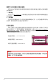
移除散熱器與風扇 1 2 3 4 5 華碩 A88XM-E 主機板使用手冊 1-7
1.4 系統記憶體 1.4.1 概述 DIMM_A1 DIMM_B1 本主機板配備兩組 240-pin DDR3(Double Data Rate,雙倍資料傳輸率)記憶體插 槽。 DDR3 記憶體模組擁有與 DDR2 記憶體模組相同的外觀,但是 DDR3 記憶體插 槽的缺口與 DDR2 記憶體插槽不同,以防止插入錯誤的記憶體模組。 DDR3 記憶體模 組可提供更高的效能,但耗電量更低。下圖所示為 DDR3 記憶體插槽在主機板上的位 置: 通道 通道 A 通道 B 插槽 DIMM_A1 DIMM_B1 A88XM-E A88XM-E 240-pin DDR3 DIMM sockets 1.4.
• 記憶體模組預設頻率依據 SPD 而變化,這是從記憶體模組存取資料的標 準方法。在預設狀態下,一些超頻記憶體模組會以低於供應商標示的頻 率運作。若要讓記憶體模組以供應商的數值或更高的頻率運作,請參考 「2.5 Ai Tweaker 選單」一節中,手動調整記憶體頻率的說明。 • 在全負載(2 DIMM)或超頻設定下,請使用更有效的散熱系統以確保 系統穩定性。 • 請造訪華碩網站(http://tw.asus.com)來獲得最新的 DDR3 記憶體合格 供應商列表(QVL)。 1.4.
取出記憶體模組 B A A 1.5 擴充插槽 考慮到未來會擴充系統效能的可能性,本主機板提供了擴充插槽,在接下來的子 章節中,將會描述主機板上這些擴充插槽的相關資訊。 安裝/移除任何擴充卡之前,請暫時先將電腦的電源線拔出。如此可免除因 電氣殘留於電腦中而發生的意外狀況。 1.5.1 安裝擴充卡 請依照下列步驟安裝擴充卡: 1. 在安裝擴充卡之前,請先詳讀該擴充卡的使用說明,並且要針對該卡作必要的硬 體設定變更。 2. 鬆開電腦主機的機殼蓋並將之取出(如果您的主機板已經放置在主機內)。 3. 找到一個您想要插入新擴充卡的空置插槽,並以十字螺絲起子鬆開該插槽位於主 機背板的金屬擋板的螺絲,最後將金屬擋板移出。 4. 將擴充卡上的金手指對齊主機板上的擴充槽,然後慢慢地插入槽中,並以目視的 方法確認擴充卡上的金手指已完全沒入擴充槽中。 5. 再用剛才鬆開的螺絲將擴充卡金屬擋板鎖在電腦主機背板以固定整張卡。 6. 將電腦主機的機殼蓋裝回鎖好。 1.5.2 設定擴充卡 在安裝好擴充卡之後,接著還須透過軟體設定來調整該擴充卡的相關設定。 1.
1.5.3 PCI 介面卡擴充插槽 本主機板配備 32 位元的 PCI 介面卡擴充插槽,舉凡網路卡、SCSI 卡、音效卡、 USB 卡等符合 PCI 介面規格者,都可以使用在 PCI 介面卡擴充插槽。 1.5.4 PCI Express 2.0 x1 介面卡擴充插槽 本主機板支援 PCI Express 2.0 x1 網路卡、SCSI 卡與其他與 PCI Express 規格相 容的卡。 1.5.5 PCI Express x16 介面卡擴充插槽 本主機板支援 PCI Express 2.
1.6 跳線選擇區 1. CMOS 組態資料清除(2-pin CLRTC) 在主機板上的 CMOS 記憶體中記載著正確的時間與系統硬體配備等資料,這 些資料並不會因電腦電源的關閉而遺失資料與時間的正確性,因為這個 CMOS 的 電源是由主機板上的鋰電池所供應。 CLRTC A88XM-E 1 2 Normal (Open) 1 2 Clear CMOS (Short) A88XM-E Clear RTC RAM 想要清除這些資料,可以依照下列步驟進行: 1. 關閉電腦電源,拔掉電源線; 2. 用一個金屬物體如螺絲起子將 CLRTC 跳線的兩個針腳短路; 3. 插上電源線,開啟電腦電源; 4.
1.7 元件與周邊裝置的連接 1.7.1 後側面板連接埠 2 1 11 10 9 3 8 7 4 5 6 1. PS/2 滑鼠連接埠(綠色):將 PS/2 滑鼠插頭連接到此連接埠。 2. VGA 連接埠:這個連接埠用來連接 VGA 顯示器或其他與 VGA 規格相容的硬體裝 置。 3. RJ-45 網路連接埠:該連接埠可經 Gigabit 網路線連接至 LAN 網路。請參考下表 中各燈的說明。 網路指示燈說明 Activity/Link 狀態 關閉 橘色 閃爍 指示燈 描述 沒有連線 已連線 資料傳輸中 ACT/LINK 指示燈 速度指示燈 狀態 描述 關閉 連線速度 10Mbps 橘色 連線速度 100Mbps 綠色 連線速度 1Gbps 4. 音效輸入連接埠(淺藍色):您可以將磁帶、CD、DVD 連接到此音效輸入連接埠。 速度 指示燈 網路連接埠 播放器等的音效輸出端 5. 音效輸出連接埠(草綠色):您可以連接耳機或喇叭等的音效接收裝置。在 2.1 聲道、4.1 聲道、5.1 聲道、7.
2.1、4.1、5.1 或 7.1 聲道音效設定 連接埠 耳機 / 2.1 聲 道喇叭輸出 4.1 聲道 喇叭輸出 5.1 聲道 喇叭輸出 7.1 聲道 喇叭輸出 淺藍色(後面板) 聲音輸入端 後置喇叭輸出 後置喇叭輸出 後置喇叭輸出 草綠色(後面板) 聲音輸出端 前置喇叭輸出 前置喇叭輸出 前置喇叭輸出 粉紅色(後面板) 麥克風輸入端 麥克風輸入端 中央/重低音喇叭輸出 中央/重低音喇叭輸 出 草綠色(前面板) – – – 側邊環繞喇叭輸出 要設定 7.1 聲道音效,請使用前面板具有 HD 音效插孔的機殼,以支援 7.1 聲道音效輸出。 7. USB 2.0 裝置連接埠 1 和 2:這二組 4-pin 通用序列匯流排(USB)連接埠可連接 到使用 USB 2.0/1.1 介面的硬體裝置。 8. USB 3.0 裝置連接埠 1 和 2:這二組 9-pin 通用序列匯流排(USB)連接埠可連接 到使用 USB 3.0/2.0 介面的硬體裝置。 • 在安裝 Windows® 作業系統時,請勿將鍵盤/滑鼠連接到任何 USB 3.
1.7.2 內部連接埠 1. 中央處理器 / 機殼風扇電源插槽(4-pin CPU_FAN、4-pin CHA_FAN) 將風扇電源接頭連接到這二組風扇電源插槽,確定每一條黑線與這些插槽的 接地端(GND)相匹配。 CPU FAN PWM CPU FAN IN CPU FAN PWR GND CPU_FAN A88XM-E CHA FAN PWM CHA FAN IN CHA FAN PWR GND CHA_FAN A88XM-E Fan connectors 千萬要記得連接風扇的電源,若系統中缺乏足夠的風量來散熱,很容易 因為主機內部溫度逐漸升高而導致當機,甚至更嚴重者會燒毀主機板上 的電子元件。注意:這些插槽並不是單純的排針,不要將跳線帽套在它 們的針腳上! • 中央處理器風扇(CPU_FAN)電源插槽最大支援 2A(24W)電源。 •僅 4-pin 中央處理器風扇和 4-pin 機殼風扇支援華碩 Fan Xpert 功能。 2.
3 ATX 主機板電源插槽(24-pin EATXPWR、4-pin ATX12V) 這些電源插槽用來連接到一個 ATX 電源供應器。電源供應器所提供的連接插 頭已經過特別設計,只能以一個特定方向插入主機板上的電源插槽。找到正確的 插入方向後,僅需穩穩地將之套進插槽中即可。 GND GND +12V DC +12V DC ATX12V A88XM-E EATXPWR +3 Volts +12 Volts +12 Volts +5V Standby Power OK PIN 1 GND +5 Volts GND +5 Volts GND +3 Volts +3 Volts GND +5 Volts +5 Volts +5 Volts -5 Volts GND GND GND PSON# GND -12 Volts +3 Volts PIN 1 A88XM-E ATX power connectors • 建議您使用符合 ATX 12 V 2.
4. Serial ATA 6.
6.
7.
10. USB 2.0 擴充套件排線插座(10-1 pin USB34、USB56) 這些 USB 擴充套件排線插槽支援 USB 2.0 規格,將 USB 模組排線連接至任何一 個插槽,接著將模組安裝到機殼後側面板中開放的插槽。這些 USB 插槽與 USB 2.0 規格相容,並支援傳送速率最高達 480Mbps。 PIN 1 USB+5V USB_P4USB_P4+ GND PIN 1 USB+5V USB_P6USB_P6+ GND A88XM-E USB+5V USB_P3USB_P3+ GND NC USB34 USB+5V USB_P5USB_P5+ GND NC USB56 A88XM-E USB2.0 connectors 請勿將 1394 排線連接到 USB 插座上,這麼做可能會導致主機板的損壞。 USB 2.0 模組需另行購買。 11. USB 3.0 擴充套件排線插槽(20-1 pin USB3_34) 這個插槽用來連接額外的 USB 3.0 連接埠模組,並與 USB 2.0 規格相容。若 您的機殼提供有 USB 3.
1.8 軟體支援 1.8.1 安裝作業系統 本主機板完全適用於 Windows® XP / Windows® 7 / 64-bit Windows® 7 / Windows® 8 / 64-bit Windows® 8 / Windows® 8.1 / 64-bit Windows® 8.1 作業系統。使用最新版本的 作業系統並且不定時地升級,是讓硬體配備得到最佳工作效率的有效方法。 • 主機板和周邊硬體裝置的選項設定繁多,請參閱您使用的作業系統說明 檔案以取得更詳盡的資訊。 • 在安裝驅動程式之前,請先確認您已經安裝 Windows® XP Service Pack 3 或更新版本 / Windows® 7 / 64-bit Windows® 7 / Windows® 8 / 64-bit Windows® 8 / Windows® 8.1 / 64-bit Windows® 8.1 作業系統,來獲得更 好的效能與系統穩定。 1.8.
1-22 第一章:產品介紹
2 BIOS 資訊 2.1 管理、更新您的 BIOS 程式 建議您先將主機板原始的 BIOS 程式備份到一片 USB 隨身碟中,以備您 往後需要再度安裝原始的 BIOS 程式。使用華碩線上更新程式來拷貝主機 板原始的 BIOS 程式。 2.1.
2.1.2 使用華碩 EZ Flash 2 更新 BIOS 程式 華碩 EZ Flash 2 程式讓您能輕鬆的更新 BIOS 程式,可以不必再到作業系統模式 下執行。 在使用此程式前,請從華碩網站上(ht tp://t w.a s u s.co m)下載最新的 BIOS 檔案。 請依據以下步驟使用 EZ Flash 2 更新 BIOS: 1. 將儲存有最新 BIOS 檔案的 USB 隨身碟插入 USB 連接埠。 2. 進入 BIOS 設定程式的進階模式(Advanced Mode)畫面,來到 Tool 選單並選擇 EZ Flash2 並按下 <Enter> 鍵將其開啟。 3. 按下 <Tab> 鍵切換到 Driver 區域。 4. 按上/下方向鍵找到儲存有最新 BIOS 檔案的 USB 隨身碟,接著按下 <Enter> 鍵。 5. 按下 <Tab> 鍵切換到 Folder Info 區域。 6.
2.1.3 使用 CrashFree BIOS 3 程式回復 BIOS 程式 華碩最新自行研發的 CrashFree BIOS 3 工具程式,讓您在當 BIOS 程式與資料被 病毒入侵或損毀時,可以輕鬆地從驅動程式與公用程式光碟中,或是從含有最新或原 始 BIOS 檔案的 USB 隨身碟中回復 BIOS 程式的資料。 • 使用此程式前,請將行動儲存裝置中的 BIOS 檔案重新命名為:A88小 XME.CAP。 • 驅動程式與公用程式光碟中的 BIOS 可能不是最新版本。請造訪華碩網 站(http://tw.asus.com)來下載最新的 BIOS 程式。 回復 BIOS 程式: 請依照下列步驟回復 BIOS 程式: 1. 啟動系統。 2. 將儲存有 BIOS 檔案的驅動程式與公用程式光碟放入光碟機,或 USB 隨身碟插入 USB 連接埠。 3. 接著工具程式便會自動檢查裝置中是否存有 BIOS 檔案。當搜尋到 BIOS 檔案後, 工具程式會開始讀取 BIOS 檔案並自動進入 EZ Flash 2 公用程式。 4.
在 DOS 環境中啟動系統 1. 將儲存有最新的 BIOS 檔案與 BIOS Updater 工具程式的 USB 隨身碟連接到電腦的 USB 連接埠。 2. 啟動電腦。當 ASUS 圖示出現時,按下 <F8> 以顯示「BIOS Boot Device Select」 選單。 Please select boot device: SATA: XXXXXXXXXXXXXXXX USB XXXXXXXXXXXXXXXXX UEFI: XXXXXXXXXXXXXXXX Enter Setup ↑ and ↓ to move selection ENTER to select boot device ESC to boot using defaults 3. 選擇 USB 隨身碟作為開機裝置。此時 DOS 畫面出現。 更新 BIOS 檔案 請依照以下步驟用 BIOS Updater 工具程式更新 BIOS 檔案: 1. 在 FreeDOS 提示符後輸入 bupdater /pc /g 並按下 <Enter>。 D:\>bupdater /pc /g 2.
3. 按下 <Tab> 鍵在各設定欄之間切換,接著用 <Up/Down/Home/End> 鍵來選擇 BIOS 檔案並按下 <Enter>。BIOS Updater 會檢查您所選擇的 BIOS 檔案並提示 您確認是否要更新 BIOS。 Are you sure to update BIOS? Yes No 4. 選擇 Yes 並按下 <Enter>。當 BIOS 更新完畢後,按 <ESC> 離開 BIOS Updater。重新啟動您的電腦。 當更新 BIOS 時,請勿關閉或重置系統!若是這麼做,將可能導致系統開 機失敗。 • 對於 BIOS Updater 1.30 或更高版本,當 BIOS 更新完畢後,工具程式會 自動回到 DOS 畫面。 • BIOS 程式的出廠預設值可讓系統運作處於最佳效能。若系統因您改變 BIOS 程式而導致不穩定,請讀取出廠預設值來保持系統的穩定。請在 「Exit」 選單中選擇 Load Optimized Defaults 項目。詳細說明請參考 「2.
2.
進入 BIOS 設定程式的預設畫面可變更。請參考「2.8 啟動選單(Boot)」 部份 Setup Mode 項目的說明。 選擇 BIOS 設定程式 的顯示語言 顯示 CPU / 主機板的溫度, CPU / 5V / 3.
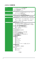
返回按鈕 選單項目 功能表列 設定值 線上操作說明 操作功能鍵 上次修改設定 設定視窗 捲軸 快速記錄 功能表列 BIOS 設定程式最上方各選單功能說明如下: My Favorites 本項目用於儲存經常使用的系統設定 Main 本項目提供系統基本設定 Ai Tweaker 本項目用於變更超頻設定 Advanced 本項目提供系統進階功能設定 Monitor 本項目顯示系統溫度、電源狀態,並變更風扇設定 Boot 本項目提供系統開啟設定 Tool Exit 本項目提供特殊功能設定 本項目提供離開 BIOS 設定程式與出廠預設值還原功能 選單項目 在功能表列選定選項時,被選擇的功能將會反白,並在選單項目區域內出現相應 的項目。 點選功能表列中的其他項目(例如:Ai Tweaker、Advanced、Monitor、Boot、Tool 與 Exit) 會出現該項目不同的選項。 返回按鈕 當進入子選單時,此按鈕會出現。按下 <Esc> 或使用 USB 滑鼠點選此按鈕回到 前一個選單畫面。 子選單 在選單畫面中,若功能選項前面有一個小三角形標記,代表此選項有子選單,您
設定視窗 在選單中選擇功能項目,然後按下 <Enter> 鍵,程式將會顯示包含此功能所提供 的選項小視窗,您可以利用此視窗來設定您所想要的設定。 捲軸 在選單畫面的右方若出現捲軸,即代表此頁選項超過可顯示的畫面,您可利用上/ 下方向鍵或是 PageUp/PageDown 鍵來切換畫面。 操作功能鍵 在選單畫面的右下方為操作功能鍵說明,請參照功能鍵說明來選擇及改變各項功 能。 線上操作說明 在選單畫面的右上方為目前所選擇的作用選項的功能說明,此說明會依選項的不 同而自動變更。 設定值 此區域顯示選單項目的設定值。這些項目中,有的功能選項僅為告知使用者目前 執行狀態,並無法更改,此類項目就會以淡灰色顯示。而可更改的項目,當您使用方 向鍵行動項目時,被選擇的項目以反白顯示。 設定值被選擇後以反白顯示。要改變設定值請選擇此項目,並按下 <Enter> 鍵以 顯示設定值列表。 快速記錄 按下此按鈕可查看您在 BIOS 中的活動記錄。 上次修改設定 按下此按鈕顯示您上一次儲存在 BIOS 中的修改訊息。 2.
在 My Favorites 中新增項目 依據以下步驟將經常使用的 BIOS 項目新增至我的最愛: 1. 使用方向鍵選擇您要新增的項目。若使用滑鼠,將指針懸停在項目上。 2. 在鍵盤上按下 ,或按下滑鼠右鍵新增項目至我的最愛頁面。 以下項目無法新增至我的最愛: • 有子選單的項目 • 使用者自訂項目,如語言和啟動順序項目 • 設定項目,如 Memory SPD Information、系統時間與日期項目 2.4 主選單(Main) 當您進入 BIOS 設定程式的進階模式(Advanced Mode)時,首先出現的第一個畫 面即為主選單。主選單顯示系統資訊概要,用來設定系統日期、時間、語言與安全設 定。 2.4.1 System Language [English] 用來選擇 BIOS 語言。設定值有:[English] [Français] [Español] [Deutsch] [Русский] [한국어] 2.4.2 System Date [Day xx/xx/xxxx] 設定您的系統日期(通常是目前的日期)。 2.4.
•若您忘記設定的 BIOS 密碼,可以採用清除 CMOS 即時時脈(RTC)記 憶體。請參閱「1.6 跳線選擇區」一節取得更多資訊。 • 螢幕上方的 Administrator Password 或 User Password 項目顯示為預設 值 [Not Installed]。設定密碼後,這些項目顯示為 [Installed]。 管理者密碼(Administrator Password) 若您已經設定了一個管理者密碼,建議您輸入管理者密碼來進入系統。否則,您 只能看到或變更 BIOS 設定程式中的部份內容。 請依照以下步驟設定系統管理者密碼: 1. 選擇 Administrator Password 項目並按下 <Enter>。 2. 在「Create New <Enter>。 Password」視窗出現時,輸入欲設定的密碼,輸入完成按下 3. 在彈出的確認視窗中再一次輸入密碼以確認密碼正確。 請依照以下步驟變更系統管理者密碼: 1. 選擇 Administrator Password 項目並按下 <Enter>。 2.
2.
Target CPU Speed : xxxxMHz 顯示目前 CPU 速度。 Target DRAM Speed : xxxxMHz 顯示目前 DRAM 速度。 2.5.1 Ai Overclock Tuner [Auto] 本項目可以讓您設定 CPU 的超頻選項來達到您所想要的 CPU 內部頻率。請選擇以 下任一種預設的超頻選項: [Auto] 自動載入系統最佳化設定值。 [Manual] 可讓您獨立設定超頻參數。 APU Frequency [XXX] 本項目只有在您將 AI Overclock Tuner 項目設定為 [Manual] 時才會出現。您可以 使用 <+> / <-> 按鍵來調整設定值,也可以透過數字鍵輸入您想要的值。設定值更改的 範圍由 90.0MHz 至 300.0MHz。 2.5.
2.5.6 記憶體時脈控制(DRAM Timing Control) 本選單中的子項目用來設定記憶體時脈控制功能。您可以使用 <+> / <-> 按鍵來調 整設定值。要回復預設設定,使用鍵盤輸入 [auto],接著按下 <Enter>。 變更此選單中的設定值可能會使系統變得不穩定!當系統出現不穩定的狀 況時,建議您使用預設值。 2.5.7 TDP 設定(TDP Configuration) 本項目是否會出現取決於安裝的 APU 類型。 Target TDP [Auto] 本項目用來手動設定一個 TDP(熱設計功耗)值。處理器將運作於指定的 TDP 範 圍內以限制功耗。 2.5.8 APU Voltage [Offset Mode] [Offset Mode] 設定正數或負數偏移電壓。 Offset Mode Sign [+] [+] [–] 設定正數值偏移電壓。 設定負數值偏移電壓。 CPU Offset Voltage [Auto] 本項目用來設定偏移電壓。設定值可在 0.00625V 到 0.33750V 範圍內,以 0.
• CPU Offset Voltage、VDDNB Offset Voltage、DRAM Voltage、SB 1.1V Voltage 項目的設定值會以不同顏色標示,表示高電壓不同的危險程度。 • 若設定電壓過高,系統需要更有效的散熱系統以保持穩定運作。 2.5.
Manual Adjustment [Fast] 本項目用來設定 CPU 電源相位控制回應。設定值有:[Ultra Fast] [Fast] [Medium] [Regular] CPU Voltage Frequency [300] 切換頻率將影響 VRM 輸出電壓的暫態回應和元件的散熱性。設定較高的頻率可獲 得較快的電壓暫態回應。使用 <+> / <-> 鍵調整設定值。設定值可在 200k Hz 到 350k Hz 範圍內,以 50k Hz 為增量調整。 CPU Power Duty Control [T.Probe] [T.Probe] [Extreme] 維持各相散熱平衡。 維持各相電流平衡。 當調整 DIGI+ VRM 相關參數時,請勿移除散熱模組。散熱情況需要監 控。 2.
2.6.
OnChip SATA Type [AHCI] 本項目用來進行 SATA 設定。 [IDE] 若您要將 Serial ATA 硬碟作為 Parallel ATA 實體儲存裝置,請設為 [IDE]。 [RAID] 若您要使用 SATA 硬碟建立 RAID 設定,請設為 [RAID]。 [AHCI] 若您要讓 Serial ATA 硬碟使用 AHCI(Advanced Host Controller Interface),請設為 [AHCI]。AHCI 允許內建儲存器開啟進階 Serial ATA 功能,透過原生命令排序技術來提升工作效能。 SATA Port 5 - Port 6 [AHCI] 只有當 OnChip SATA Type 項目設為 [AHCI] 時此項目才會出現。若連接 埠 5、6 設為 [AHCI],這些連接埠只能在作業系統下,安裝了驅動程式後使 用。若設為 [IDE],可在進入作業系統前存取連接埠 5、6 上的裝置。設定值 有:[AHCI] [IDE] SATA Port 5 - Port 6 [RAID] 只有當 OnChip SATA Type 項目設為 [RAID] 時此項目才
Legacy USB Support [Enabled] [Enabled] [Disabled] [Auto] 開啟 Legacy 作業系統對 USB 裝置的支援。 USB 裝置僅在 BIOS 設定程式中可用。 允許系統在開機時偵測是否存在 USB 裝置。若存在,USB 控制器 legacy 模式開啟。若不存在,legacy USB 支援功能關閉。 EHCI Hand-off [Disabled] [Enabled] [Disabled] 開啟對不支援 EHCI hand‑off 功能的作業系統支援。 關閉此功能。 USB Single Port Control 本項目用來開啟或關閉單獨的 USB 連接埠。 2.6.
Front Panel Type [HD] 依據前面板音效模組支援的音效標準,設定前面板音效連接埠(AAFP)模式為 legacy AC’97 或高傳真音效。 [HD] 將前面板音效連接埠(AAFP)模式設定為高傳真音效。 [AC97] 將前面板音效連接埠(AAFP)模式設定為 legacy AC’97。 SPDIF Out Type [SPDIF] [SPDIF] [HDMI] 設定為 [SPDIF] 以使用 SPDIF 音效輸出。 設定為 [HDMI] 以使用 HDMI 音效輸出。 Realtek LAN Controller [Enabled] [Enabled] [Disabled] 開啟 Realtek LAN 控制器。 關閉此控制器。 Realtek PXE OPROM [Disabled] 只有當將 Realtek LAN Controller 項目設定為 [Enabled] 時,此項目才會出現,用 來開啟或關閉 Realtek LAN 控制器的 Rom 幫助。設定值有:[Enabled] [Disabled] Charging USB devices in Power
WOL (include AC Power Loss) [Disabled] [Disabled] [Enabled] 電源中斷(G3 狀態)後關閉網路喚醒功能。 電源中斷(G3 狀態)後開啟網路喚醒功能。 Power On By PS/2 Keyboard [Disabled] [Disabled] 關閉 PS/2 鍵盤喚醒功能。 [Space Bar] 可使用 PS/2 鍵盤的空白鍵喚醒系統。 [Ctrl-Esc] 可使用 PS/2 鍵盤的 Ctrl+Esc 鍵喚醒系統。 [Power Key] 可使用 PS/2 鍵盤的電源鍵喚醒系統。要使用本功能,ATX 電源必須 可提供至少 1A 的電流與 +5VSB 的電壓。 Power On By PME [Disabled] [Disabled] [Enabled] 關閉透過 PCI/PCIE 裝置將 PME 從 S5 喚醒。 用來開啟 PCI/PCIE 網路卡或數據機卡喚醒系統。要使用本功能,ATX 電源必須可提供至少 1A 的電流與 +5VSB 的電壓。 Power On By Ring [Disabled] [Dis
2.
2.7.1 CPU Temperature / MB Temperature [xxx℃/xxx℉] 本主機板具備了中央處理器 / 主機板的溫度感測器,可自動偵測並顯示目前處理器 的溫度。若您不想顯示偵測到的溫度,請選擇 [Ignored]。 2.7.2 CPU / Chassis Fan Speed [xxxx RPM] / [N/A] 主機板具備中央處理器 / 電源風扇轉速 RPM(Rotations Per Minute)監控功能。如 果主機板上沒有連接風扇,這裡會顯示 [N/A]。 2.7.
2.7.
2.
2.8.
POST Delay Time [3 sec] 只有當 Full Screen Logo 項目設為 [Enabled] 時此項目才會出現,用來設定系統顯示 開機自我測試報告的等待時間。本設定僅在正常啟動模式下有效。設定值從 1 秒至 10 秒。 本設定僅在正常啟動模式下有效。 Post Report [5 sec] 只有當 Full Screen Logo 項目設為 [Disabled] 時此項目才會出現,用來設定系統 顯示自我測試(Post)報告的等待時間。設定值從 1 秒至 10 秒。 2.8.3 Bootup NumLock State [On] [On] [Off] 使 NumLock 鍵開機時自動啟動。 使 NumLock 鍵開機時不自動啟動。 2.8.4 Wait For‘F1’If Error [Enabled] 當您將本項目設為 [Enabled],那麼系統在開機過程出現錯誤訊息時,將會等待您 按下 <F1> 鍵確認才會繼續進行開機程式。設定值有:[Disabled] [Enabled] 2.8.
只有當 Launch CSM 項目設為 [Enabled] 時,以下四個項目才會出現。 Boot Devices Control [UEFI and Legacy OpROM] 本項目用來選擇啟動裝置的類型。設定值有:[UEFI and Legacy OpROM] [Legacy OpROM only] [UEFI only] Boot from Network Devices [Legacy OpROM first] 本項目用來選擇您想要啟動的網路裝置類型。設定值有:[Legacy OpROM first] [UEFI driver first] [Ignore] Boot from Storage Devices [Legacy OpROM first] 本項目用來選擇您想要啟動的儲存裝置類型。設定值有:[Both, Legacy OpROM first] [Both, UEFI first] [Legacy OpROM first] [UEFI driver first] [Ignore] Boot from PCIe/PCI Expansion Devices [Legacy OpROM fi
Save Secure Boot keys 只有當載入預設安全啟動金鑰後此項目才會出現。用來儲存所有安全啟動金鑰 至 USB 儲存裝置。 PK Management 平臺金鑰 (PK) 鎖定並保護固件未經允許不得更改。系統會在系統進入作業系統 之前驗證 PK。 Delete PK 本項目用來從系統刪除 PK。一旦 PK 被刪除,整個系統的安全啟動金鑰將無 法開啟。設定值有:[Yes] [No] Load PK from File 本項目用來從 USB 儲存裝置載入已下載的 PK。 PK 檔案必須格式化為一個基於時間認證變量的 UEFI 變量結構。 KEK Management KEK(金鑰交換金鑰或金鑰註冊金鑰)管理簽名資料庫(db)與撤銷簽名資料庫 (dbx)。 金鑰交換金鑰 (KEK) 指的是 Microsoft® Secure Boot Key-Enrollment Key (KEK)。 Delete the KEK 本項目用來從系統刪除 KEK。設定值有:[Yes] [No] Load KEK from File 本項目用來載入從 USB 儲存裝置載入已下載的 KEK。 Append K
DBX Management dbx(撤銷簽名資料庫)列出了 db 項目中不再被信任且不能被載入的被禁止映 像檔。 Delete the dbx 本項目用來從系統刪除 dbx。設定值有:[Yes] [No] Load dbx from File 本項目用來從 USB 儲存裝置載入已下載的 dbx。 Append dbx from file 本項目用來從儲存裝置載入額外的 dbx 以使更多 db 的映像檔無法被載入。 dbx 檔案必須格式化為一個基於時間認證變量的 UEFI 變量結構。 2.8.10 啟動項目順序(Boot Option Priorities) 這些項目讓您自行選擇啟動磁碟並排列開機裝置順序。螢幕上顯示的裝置數量依 據系統中安裝的裝置而定。 • 要選擇系統開機的啟動裝置,請在 ASUS 的圖示出現時按下 <F8>。 • 要以安全模式進入 Windows® 作業系統,請在開機自我測試完成後,按 下 <F8>。 2.8.
2.9 工具選單(Tool) 本工具選單可以讓您針對特別功能進行設定。請選擇選單中的選項並按下 <Enter> 鍵來顯示子選單。 2.9.1 ASUS EZ Flash 2 Utility 本項目可以讓您執行 ASUS EZ Flash 2。當您按下 <Enter> 鍵後,華碩 EZ Flash 2 螢幕會出現。 更多詳細資訊,請參考「2.1.2 使用華碩 EZ Flash 2 更新 BIOS 程式」部 份的說明。 2.9.2 ASUS SPD Information DIMM Slot # [DIMM_A1] 本項目用來顯示安裝在選定插槽的記憶體模組的 SPD(Serial Presence Detect)資 訊。設定值有:[DIMM_A1] [DIMM_B1] 2.9.3 ASUS O.C.
2.
華碩的連絡資訊 華碩電腦公司 ASUSTeK COMPUTER INC.(台灣) 市場訊息 技術支援 地址: 台灣臺北市北投區立德路 15 號 電話: +886-2-2894-3447 傳真: +886-2-2890-7798 電子郵件: info@asus.com.tw 全球資訊網:http://tw.asus.com 電話: +886-2-2894-3447(0800-093456) 線上支援: http://www.asus.com/tw/support/ 華碩電腦公司 ASUSTeK COMPUTER INC.(亞太地區) 市場訊息 技術支援 地址: 台灣臺北市北投區立德路 15 號 電話: +886-2-2894-3447 傳真: +886-2-2890-7798 電子郵件: info@asus.com.tw 全球資訊網:http://tw.asus.com 電話: +86-21-38429911 傳真: +86-21-58668722, ext. 9101# 線上支援: http://www.asus.
(510)739-3777/(510)608-4555 800 Corporate Way, Fremont, CA 94539. Asus Computer International Date : Signature : Representative Person’s Name : Mar. 26, 2014 Steve Chang / President This device complies with part 15 of the FCC Rules. Operation is subject to the following two conditions: (1) This device may not cause harmful interference, and (2) this device must accept any interference received, including interference that may cause undesired operation.