User Guide Motherboard A8S-X
E2123 Checklist First Edition July 2005 Copyright © 2005ASUSTeK COMPUTER INC. All Rights Reserved. No part of this manual, including the products and software described in it, may be reproduced, transmitted, transcribed, stored in a retrieval system, or translated into any language in any form or by any means, except documentation kept by the purchaser for backup purposes, without the express written permission of ASUSTeK COMPUTER INC. (“ASUS”).
Contents Features Notices ........................................................................................... vi Safety information ......................................................................... vii About this guide ............................................................................ viii Conventions used in this guide ........................................... viii Typography ..........................................................................
Contents Safeguards Chapter 2: BIOS Information 2.1 Managing and updating your BIOS .................................... 2-2 2.1.1 Creating a bootable floppy disk ............................. 2-2 2.1.2 Using AFUDOS to update the BIOS ...................... 2-3 2.1.3 Using AFUDOS to copy BIOS from PC ................. 2-4 2.1.4 Using ASUS EZ Flash to update the BIOS ............ 2-5 2.1.5 Recovering the BIOS with CrashFree BIOS 2 ....... 2-6 2.2 BIOS Setup program ..........................................
Contents 2.6 2.7 2.5.4 ACPI APIC Support .............................................. 2-23 2.5.5 APM Configuration ............................................... 2-24 2.5.6 Hardware Monitor ................................................ 2-25 Boot menu ........................................................................ 2-26 2.6.1 Boot Device Priority ............................................. 2-26 2.6.2 Boot Settings Configuration ................................. 2-27 2.6.3 Security ........
Notices Federal Communications Commission Statement This device complies with Part 15 of the FCC Rules. Operation is subject to the following two conditions: • This device may not cause harmful interference, and • This device must accept any interference received including interference that may cause undesired operation. The use of shielded cables for connection of the monitor to the graphics card is required to assure compliance with FCC regulations.
Safety information Electrical safety • To prevent electrical shock hazard, disconnect the power cable from the electrical outlet before relocating the system. • When adding or removing devices to or from the system, ensure that the power cables for the devices are unplugged before the signal cables are connected. If possible, disconnect all power cables from the existing system before you add a device.
About this guide Conventions used in this guide To make sure that you perform certain tasks properly, take note of the following symbols used throughout this manual. WARNING: Information to prevent injury to yourself when trying to complete a task. CAUTION: Information to prevent damage to the components when trying to complete a task. IMPORTANT: Information that you MUST follow to complete a task. NOTE: Tips and additional information to aid in completing a task.
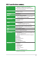
A8S-X specifications summary CPU Socket 939 for AMD Athlon™ 64 X2/AMD Athlon™ FX/ AMD Athlon™ 64/AMD Sempron™ processors Supports AMD 64 architecture that enables simultaneous 32-bit and 64-bit architecture Chipset NorthBridge: SiS 756 SouthBridge: SiS 965L System Bus 2000/1600 MT/s Memory Dual-channel memory architecture 4 x 184-pin DDR DIMM sockets for up to 4GB non-ECC PC3200/PC2700/PC2100 DDR DIMMs Expansion slots 1 x PCI Express x16 slot 2 x PCI Express x1 slot 3 x PCI slots Storage South Br
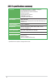
A8S-X specifications summary Internal I/O 2 x USB 2.0 connector for 4 additional USB ports CPU/chassis/power fan connectors 24-pin/4-pin ATX 12V power connectors CD/AUX connectors Chassis intrusion connector GAME/MIDI connector Front panel audio connector BIOS features 4Mb Flash ROM AMI BIOS with enhanced ACPI, PnP, DMI, ASUS MyLogo™, SM BIOS 2.3 Industry standard PCI 2.2, USB 2.0/1.1 Manageability WfM 2.0, DMI, WOL by PME, WOR by PME, Chassis intrusion, SM BIOS 2.
Chapter 1 This chapter describes the features of the motherboard. It includes brief descriptions of the motherboard components, and illustrations of the layout, jumper settings, and connectors.
1.1 Welcome! Thank you for buying the ASUS® A8S-X motherboard! The motherboard delivers a host of new features and latest technologies making it another standout in the long line of ASUS quality motherboards! The motherboard combines the powers of the AMD Athlon™ 64 X2, AMD Athlon™ 64 FX, AMD Athlon™ 64 or AMD Sempron™ processor and the SiS 756 chipset to set a new benchmark for an effective desktop platform solution.
1.3 Special features 1.3.1 Product Highlights AMD Dual-Core Architecture The motherboard supports AMD dual-core processors containing two physical CPU cores with discrete L2 cache structure for each core to meet demands for more powerful computing. See page 1-8. Latest processor technology The AMD Athlon™ 64FX and Athlon™ 64 desktop processors are based on AMD’s 64-bit and 32-bit architecture, which represents the landmark introduction of the industry’s first x86-64 technology.
PCI Express™ interface The motherboard fully supports PCI Express, the latest I/O interconnect technology that speeds up the PCI bus. PCI Express features point-to-point serial interconnections between devices and allows higher clockspeeds by carrying data in packets. This high speed interface is software compatible with existing PCI specifications. See page 1-13 for details. USB 2.0 technology The motherboard implements the Universal Serial Bus 2.0 (USB 2.
1.4 Before you proceed Take note of the following precautions before you install motherboard components or change any motherboard settings. 1. Unplug the power cord from the wall socket before touching any component. 2. Use a grounded wrist strap or touch a safely grounded object or to a metal object, such as the power supply case, before handling components to avoid damaging them due to static electricity. 3. Hold components by the edges to avoid touching the ICs on them. 4.
1.5 Motherboard overview 1.5.1 Motherboard layout 18.3cm (8.6in) PWR_FAN Top: CD SEC_IDE Top:Line In Center:Line Out Below:Mic In EATXPWR USB3 RJ-45 USB4 SiS 756 30.
1.5.2 Placement direction When installing the motherboard, make sure that you place it into the chassis in the correct orientation. The edge with external ports goes to the rear part of the chassis as indicated in the image below. 1.5.3 Screw holes Place six (6) screws into the holes indicated by circles to secure the motherboard to the chassis. Do not overtighten the screws! Doing so may damage the motherboard.
1.6 Central Processing Unit (CPU) 1.6.1 Overview The motherboard comes with a surface mount 939-pin Zero Insertion Force (ZIF) socket designed for the AMD Athlon™ 64 X2, AMD Athlon™ 64 FX and AMD Athlon™ 64 processors. The 128-bit-wide data paths of these processors can run applications faster than processors with only 32-bit or 64-bit wide data paths.
1.6.2 Installing the CPU Follow these steps to install a CPU. 1. Locate the 939-pin ZIF socket on the motherboard. 2. Unlock the socket by pressing the lever sideways, then lift it up to a 90°-100° angle. Socket Lever Make sure that the socket lever is lifted up to 90°-100° angle, otherwise the CPU does not fit in completely. 3. Position the CPU above the socket such that the CPU corner with the gold triangle matches the socket corner with a small triangle. 4.
1.7 System memory 1.7.1 DIMM sockets location DIMM_B2 DIMM_A2 DIMM_B1 DIMM_A1 The following figure illustrates the location of the DDR DIMM sockets. A8S-X ® A8S-X 184-pin DDR DIMM sockets • Make sure to unplug the power supply before adding or removing DIMMs or other system components. Failure to do so may cause severe damage to both the motherboard and the components. • We recommend to install the memory modules first before installing a PCI Express x16 card. 1.7.
1.7.3 Installing a DIMM DDR DIMM Follow these steps to install a DIMM. 1. Unlock a DIMM socket by pressing the retaining clips outward. 2. Align a DIMM on the socket such that the notch on the DIMM matches the break on the socket. 3. Firmly insert the DIMM into the socket until the retaining clips snap back in place and the DIMM is properly seated. Unlocked A DDR DIMM is keyed with a notch so that it fits in only one direction. DO NOT force a DIMM into a socket to avoid damaging the DIMM. 1.
1.8.2 IRQ assignments for this motherboard A PCI slot 1 PCI slot 2 PCI slot 3 PCIe x1 slot 1 PCIe x1 slot 2 PCIe x16 slot Onboard USB controller 1 Onboard USB controller 2 Onboard USB controller 3 Onboard USB 2.
1.8.4 PCI Express x1 slot This motherboard supports PCI Express x1 network cards, SCSI cards and other cards that comply with the PCI Express specifications. The figure shows a network card installed on the PCI Express x1 slot. 1.8.5 PCI Express x16 slot This motherboard supports PCI Express x16 graphic cards that comply with the PCI Express specifications. The following figure shows a graphics card installed on the PCI Express x16 slot.
1.9 Jumpers 1. Clear RTC RAM (CLRTC) This jumper allows you to clear the Real Time Clock (RTC) RAM in CMOS. You can clear the CMOS memory of date, time, and system setup parameters by erasing the CMOS RTC RAM data. The RAM data in CMOS, that include system setup information such as system • words, is powered by the onboard button cell battery. To erase the RTC RAM: 1. Turn OFF the computer and unplug the power cord. 2. Move the jumper cap from pins 1-2 (default) to pins 2-3.
2. USB device wake-up (3-pin USBPW12, USBPW34, USBPW56, USBPW78) Set these jumpers to +5V to wake up the computer from S1 sleep mode (CPU stopped, DRAM refreshed, system running in low power mode) using the connected USB devices. Set to +5VSB to wake up from S3 and S4 sleep modes (no power to CPU, DRAM in slow refresh, power supply in reduced power mode).
1.10 Connectors This section describes and illustrates the motherboard rear panel and internal connectors. 1.10.1 Rear panel connectors 1 2 3 4 5 6 10 11 9 8 7 1. PS/2 mouse port. This green 6-pin connector is for a PS/2 mouse. 2. Parallel port. This 25-pin port connects a parallel printer, a scanner, or other devices. 3. RJ-45 port. This port allows connection to a Local Area Network (LAN) through a network hub. Refer to the table below for the LAN port LED indications. 4. Line In jack.
1.10.2 Internal connectors 1. IDE connectors (40-1 pin PRI_IDE, SEC_IDE) This connector supports the provided UltraATA133 IDE hard disk ribbon cable. Connect the cable’s blue connector to the primary (recommended) or secondary IDE connector, then connect the gray connector to the UltraATA133 slave device (hard disk drive) and the black connector to the UltraATA133 master device. • Pin 20 on each IDE connector is removed to match the covered hole on the UltraATA cable connector.
3. ATX power connectors (24-pin ATXPWR, 4-pin ATX12V) These connectors are for an ATX power supply plugs. The power supply plugs are designed to fit these connectors in only one orientation. Find the proper orientation and push down firmly until the connectors completely fit. • Use of an ATX 12 V Specification 2.0-compliant power supply unit (PSU) that provides a minimum power of 350 W is recommended for a fullyconfigured system.
5. CPU and chassis fan connectors (3-pin CPU_FAN, CHA_FAN, PWR_FAN) The fan connectors support cooling fans of 350mA~740mA (8.88W max.) or a total of 1A~2.22A (26.64W max.) at +12V. Connect the fan cables to the fan connectors on the motherboard, making sure that the black wire of each cable matches the ground pin of the connector. GND +12V Rotation GND +12V Rotation Do not forget to connect the fan cables to the fan connectors.
7. Chassis intrusion connector (4-1 pin CHASSIS) This lead is for a chassis designed with intrusion detection feature. This requires an external detection mechanism such as a chassis intrusion sensor or microswitch. When you remove any chassis component, the sensor triggers and sends a high-level signal to this lead to record a chassis intrusion event. Chassis Signal GND +5VSB_MB By default, the pins labeled “Chassis Signal” and “Ground” are shorted with a jumper cap.
9. Serial ATA connectors (7-pin SATA1, SATA2) These next generation connectors support the thin Serial ATA cables for primary internal storage devices. The current Serial ATA interface allows up to 150 MB/s data transfer rate, faster than the standard parallel ATA with 133MB/s (Ultra ATA/133). A8S-X SATA connectors SATA2 SATA1 GND RSATA_TXP1 RSATA_TXN1 GND RSATA_RXP1 RSATA_RXN1 GND ® GND RSATA_TXP2 RSATA_TXN2 GND RSATA_RXP2 RSATA_RXN2 GND A8S-X 10.
12. System panel connector (10-1 pin PANEL) This connector accommodates several system front panel functions. SPEAKER +5V Ground Ground Speaker PLED+ PLED- PLED ® IDE_LED Reset Ground A8S-X PWR Ground IDE_LED+ IDE_LED- PANEL RESET PWRSW * Requires an ATX power supply. A8S-X System panel connector • System Power LED Lead (Green 3-pin PLED) This 3-pin connector connects to the system power LED. The LED lights up when you turn on the system power, and blinks when the system is in sleep mode.
Chapter 2 This chapter tells how to change system settings through the BIOS Setup menus. Detailed descriptions of the BIOS parameters are also provided.
2.1 Managing and updating your BIOS The following utilities allow you to manage and update the motherboard Basic Input/Output System (BIOS) setup. 1. ASUS AFUDOS - Updates the BIOS using a bootable floppy disk in DOS mode. 2. ASUS EZ Flash - Updates the BIOS using a floppy disk during POST. 3. ASUS CrashFree BIOS 2 - Updates the BIOS using a bootable floppy disk or the motherboard support CD. Refer to the corresponding sections for details on these utilities. Important notes • • 2.1.
d. From the Open field, type D:\bootdisk\makeboot a: assuming that D: is your optical drive. e. Press , then follow screen instructions to continue. 2. Copy the original or the latest motherboard BIOS file to the bootable floppy disk. 2.1.2 Using AFUDOS to update the BIOS To update the BIOS using the AFUDOS.EXE utility: 1. Visit the ASUS website (www.asus.com) to download the latest BIOS file for your motherboard. Save the BIOS file to a bootable floppy disk.
When the BIOS update process is complete, the utility returns to the DOS prompt. A:\>afudos /iA8S-X.ROM AMI Firmware Update Utility - Version 1.10 Copyright (C) 2002 American Megatrends, Inc. All rights reserved. Reading file ..... Erasing flash .... Writing flash .... Verifying flash .. done done 0x0008CC00 (9%) done A:\> 5. Reboot the system from the hard disk. 2.1.3 Using AFUDOS to copy BIOS from PC You can use the AFUDOS.
3. The utility will copy the current system BIOS by default to the floppy disk. Make sure that the floppy disk has at least 600KB of free disk space and is not writeprotected. A:\>afudos /oMYBIOS03.ROM AMI Firmware Update Utility - Version 1.10 Copyright (C) 2002 American Megatrends, Inc. All rights reserved. Reading flash ..... done A:\> When the copy process is complete, the utility returns to the DOS prompt. 2.1.
DO NOT shutdown or reset the system while updating the BIOS! Doing so may cause system boot failure! User recovery requested. Starting BIOS recovery... Checking for floppy... Floppy found! Reading file “A8S-X.ROM”. Completed. Start flashing... Flashed successfully. Rebooting. 2.1.
Bad BIOS checksum. Starting BIOS recovery... Checking for floppy... Floppy found! Reading file “A8S-X.ROM”. Completed. Start flashing... DO NOT shut down or reset the system while updating the BIOS! Doing so may cause system boot failure! 2. When the BIOS update process is complete, reboot the system. To recover the BIOS from the support CD: 1. Boot the system. 2. When a corrupted BIOS is detected, the following screen message appears. Bad BIOS checksum. Starting BIOS recovery... Checking for floppy...
2.2 BIOS Setup program This motherboard supports a programmable LPC chip that you can update using the provided utility described in section “2.1 Managing and updating your BIOS.” Use the BIOS Setup program when you are installing a motherboard, reconfiguring your system, or prompted to “Run Setup”. This section explains how to configure your system using this utility. Even if you are not prompted to use the Setup program, you may want to change the configuration of your computer in the future.
2.2.1 BIOS menu screen Menu items Menu bar Configuration fields System Time System Date Legacy Diskette A Language Primary IDE Master Primary IDE Slave Secondary IDE Master Secondary IDE Slave Third IDE Master Fourth IDE Master Onboard PCI S-ATA Controller [11:51:19] [Thu 08/05/2003] [1.44M, 3.5 in] [English] : [ST320413A] : [ASUS CD-S520/A] : [Not Detected] : [Not Detected] : [Not Detected] : [Not Detected] [Native] General help Use [ENTER], [TAB] or [SHIFT-TAB] to select a field.
2.2.4 Menu items The highlighted item on the menu bar displays the specific items for that menu. For example, selecting Main shows the Main menu items. The other items (Advanced, Power, Boot, and Exit) on the menu bar have their respective menu items. System Time System Date Legacy Diskette A [11:51:19] [Thu 07/05/2005] [1.44M, 3.
2.3 Main menu When you enter the BIOS Setup program, the Main menu screen appears giving you an overview of the basic system information. Refer to section “2.2.1 BIOS menu screen” for information on the menu screen items and how to navigate through them. System Time System Date Legacy Diskette A Language Primary IDE Master Primary IDE Slave Secondary IDE Master Secondary IDE Slave Third IDE Master Fourth IDE Master Onboard PCI S-ATA Controller [11:51:19] [Thu 08/05/2003] [1.44M, 3.
2.3.5 Primary, Secondary, Third and Fourth IDE Master/Primary and Secondary IDE Slave While entering Setup, BIOS auto-detects the presence of IDE devices. There is a separate sub-menu for each IDE device. Select a device item then press to display the IDE device information. Primary IDE Master Device : Hard Disk Vendor : ST320413A Size : 20.
PIO Mode [Auto] Selects the PIO mode. Configuration options: [Auto] [0] [1] [2] [3] [4] DMA Mode [Auto] Selects the DMA mode. Configuration options: [Auto] [SWDMA0] [SWDMA1] [SWDMA2] [MWDMA0] [MWDMA1] [MWDMA2] [UDMA0] [UDMA1] [UDMA2] [UDMA3] [UDMA4] [UDMA5] SMART Monitoring [Auto] Sets the Smart Monitoring, Analysis, and Reporting Technology. Configuration options: [Auto] [Disabled] [Enabled] 32Bit Data Transfer [Disabled] Enables or disables 32-bit data transfer.
2.4 Advanced menu The Advanced menu items allow you to change the settings for the CPU and other system devices. Take caution when changing the settings of the Advanced menu items. Incorrect field values may cause the system to malfunction. JumperFree Configuration USB Configuration CPU Configuration Chipset Onboard Devices Configuration PCI PnP AMD Cool ‘N Quiet Configuration 2.4.
PCI Clock Synchronization Mode [To PCI Express] Sets the PCI Express clock synchronization mode. Configuration options: [To PCI Express] [33.33MHz] [37.5MHz] [40.0MHz] DDR Reference Voltage [Auto] Allows you to automatically detect or select from a list the DDR operating voltage. Configuration options: [2.6V] [2.7V] [2.8V] [2.9V] [Auto] FID/VID Change [Auto] Sets the frequency ID and voltage ID.
The Module Version and USB Devices Enabled items show the auto-detected values. If no USB device is detected, the item shows None. Legacy USB Support [Auto] Allows you to enable or disable the legacy USB support. When set to Auto, the system disables the legacy USB support if there are no USB devices connected. Configuration options: [Disabled] [Enabled] [Auto] USB 2.0 Controller Mode [HiSpeed] Allows you to configure the USB 2.0 controller in HiSpeed (480 Mbps) or Full Speed (12 Mbps).
2.4.4 Chipset The Chipset menu items allow you to change the advanced chipset settings. Select an item then press to display the sub-menu. Chipset Settings PCI Express (Dev1) Configuration NorthBridge Configuration HyperTransport Configuration PCI Express (Dev1) Configuration PCI Express (Dev1) Configuration Primary Graphics Adapter [PCI Express Card] Primary Graphics Adapter [PCI Express Card] Sets the primary graphics adapter.
Memory Configuration Memory Configuration Memclock Mode MCT Timing Mode Software Memory Hole [Auto] [Auto] [Disabled] Memclock Mode [ Auto] Allows you to set the memory clock mode. Set by the code using [Auto] or select [Manual] to set using one of the standard values. Configuration options: [Auto] [Limit] MCT Timing Mode [ Auto] Allows you to set the MCT timing mode. Set by the code using [Auto] or select [Manual] to set using one of the standard values.
TRFC [Auto] Sets the TRFC. Configuration options: [Auto] [9T] [10T] [11T] [12T] [13T] [14T] [15T] [16T] TRWT [Auto] Sets the TRWT. Configuration options: [Auto] [1 CLK] [2 CLK] [3 CLK] [4 CLK] [5 CLK] [6 CLK] Software Memory Hole [Disabled] Enables or disables the software memory remapping around the memory hole. Configuration options: [Disabled] [Enabled] Hardware Memory Hole item appears instead of Software Memory Hole if you installed a Revision E0 processor.
2.4.5 Onboard Devices Configuration Serial Port1 Address Serial Port1 Mode Parallel Port Address Onboard Game Port Onboard MIDI Port [3F8/IRQ4] [Normal] [378] [Disabled] [Disabled] Onboard LAN Onboard LAN Boot ROM Onboard AC97 Audio DEVICE [Enabled] [Disabled] [Enabled] Serial Port1 Address [3F8/IRQ4] Allows you to select the Serial Port1 base address. Configuration options: [Disabled] [3F8/IRQ4] [2F8/IRQ3] [3E8/IRQ4] [2E8/IRQ3] Serial Port Mode [Normal] Allows you to select the Serial Port mode.
Onboard MIDI Port [Disabled] Disables or sets the onboard MIDI port. Configuration options: [Disabled] [300] [330] OnBoard LAN [Enabled] Allows you to enable or disable the onboard LAN controller. Configuration options: [Disabled] [Enabled] Onboard LAN Boot ROM [Disabled] Allows you to enable or disable the onboard LAN boot ROM. Configuration options: [Disabled] [Enabled] OnBoard AC’97 Audio DEVICE [Enabled] Allows the BIOS to detect whether you are using any audio device.
PCI Latency Timer [64] Allows you to select the value in units of PCI clocks for the PCI device latency timer register. Configuration options: [32] [64] [96] [128] [160] [192] [224] [248] Allocate IRQ to PCI VGA [Yes] When set to [Yes], BIOS assigns an IRQ to PCI VGA card if the card requests for an IRQ. When set to [No], BIOS does not assign an IRQ to the PCI VGA card even if requested.
2.5 Power menu The Power menu items allow you to change the settings for the Advanced Power Management (APM) feature. Select an item then press to display the configuration options. Suspend Mode Repost Video on S3 Resume ACPI 2.0 Support ACPI APIC Support [S1 & S3 (STR)] [No] [No] [Enabled] APM Configuration Hardware Monitor 2.5.1 Suspend Mode [S1 & S3 (STR)] Allows you to select the ACPI state to be used for system suspend.
2.5.5 APM Configuration Power Button Mode [On/Off] Restore on AC Power Loss Power On By PS2 Keyboard Power On By PS2 MOUSE Power On By PCI Devices Power On By External Modem Power On By RTC Alarm [Always OFF] [Disabled] [Disabled] [Disabled] [Disabled] [Disabled] Power Button Mode [On/Off] Allows the system to go into On/Off mode or suspend mode when the power button is pressed.
Power On By RTC Alarm [Disabled] Allows you to enable or disable RTC to generate a wake event. When this item is set to Enabled, the items RTC Alarm Date, RTC Alarm Hour, RTC Alarm Minute, and RTC Alarm Second appear with set values. Configuration options: [Disabled] [Enabled] 2.5.6 Hardware Monitor CPU Temperature Hardware Monitor CPU Temperature MB Temperature [40.5ºC/102.5ºF] [33ªC/91ºF] CPU Fan Speed Chassis Fan Speed Power Fan Speed [3260RPM] [N/A] [N/A] VCORE Voltage 3.
2.6 Boot menu The Boot menu items allow you to change the system boot options. Select an item then press to display the sub-menu. Boot Settings Specifies the Boot Device Priority sequence. Boot Device Priority Boot Settings Configuration Security 2.6.
2.6.2 Boot Settings Configuration Boot Settings Configuration Quick Boot Full Screen Logo AddOn ROM Display Mode Bootup Num-Lock PS/2 Mouse Support Wait for ‘F1’ If Error Hit ‘DEL’ Message Display Interrupt 19 Capture [Enabled] [Enabled] [Force BIOS] [On] [Auto] [Enabled] [Enabled] [Disabled] Allows BIOS to skip certain tests while booting. This will decrease the time needed to boot the system.
Interrupt 19 Capture [Disabled] When set to [Enabled], this function allows the option ROMs to trap Interrupt 19. Configuration options: [Disabled] [Enabled] 2.6.3 Security The Security menu items allow you to change the system security settings. Select an item then press to display the configuration options. Security Settings Supervisor Password User Password : Not Installed : Not Installed to change password. again to disable password.
Security Settings Supervisor Password User Password : Installed : Not Installed Change Supervisor Password User Access Level Change User Password Clear User Password Password Check to change password. again to disabled password. [Full Access] [Setup] User Access Level (Full Access] Allows you to select the access restriction to the Setup items. Configuration options: [No Access] [View Only] [Limited] [Full Access] No Access prevents user access to the Setup utility.
2.7 Exit menu The Exit menu items allow you to load the optimal or failsafe default values for the BIOS items, and save or discard your changes to the BIOS items. Exit Options Exit & Save Changes Exit & Discard Changes Discard Changes Exit system setup after saving the changes. F10 key can be used for this operation. Load Setup Defaults Pressing does not immediately exit this menu. Select one of the options from this menu or from the legend bar to exit.
Chapter 3 This chapter describes the contents of the support CD that comes with the motherboard package.
3.1 Install an operating system This motherboard supports Windows® 2000/XP operating system (OS). Always install the latest OS version and corresponding updates to maximize the features of your hardware. Motherboard settings and hardware options vary, so use the setup procedures presented in this chapter for general reference only. Refer to your OS documentation for more information. 3.
3.2.2 Drivers menu The drivers menu shows the available device drivers if the system detects installed devices. Install the necessary drivers to activate the devices. ASUS InstAll - Installation Wizard for Drivers Executes the ASUS installation wizard for drivers. AMD Cool ‘n’ Quiet Driver Installs the AMD Cool ‘n’ Quiet! technology drivers. SIS RAID Controller Driver Install the SIS RAID Controller drivers. SoundMAX ADI1986A Audio Driver Installs the SoundMAX ADI1986A audio driver and application.
ASUS PC Probe II This smart utility monitors the fan speed, CPU temperature, and system voltages, and alerts you on any detected problems. This utility helps you keep your computer at a healthy operating condition. Install ASUS Update This program allows you to download the latest version of the BIOS from the ASUS website. Before using the ASUS Update, make sure that you have an Internet connection so you can connect to the ASUS website. Installing ASUS Update also installs ASUS Mylogo™.
3.2.4 Make Disk Make SIS RAID Controller Driver Disk Creates the SIS RAID controller driver disk. 3.2.5 Manual SIS965/SIS965L SATA RAID User’s Manual Allows you to open the SIS965/SIS965L Serial ATA RAID user’s manual.
3.2.6 ASUS Contact Information Clicking the ASUS Contact Information tab displays as stated. You may also find this information on the inside front cover of this user guide.