AAM6020VI-T4 CPE User Manual AAM6020VI-T4 User Manual Rev. 1.
AAM6020VI-T4 User Manual Table of Contents 1. Introduction 1.1 Features & System Requirements 2. Your CPE at a glance 2.1 Ports and buttons (Back panel) 2.2 LED description (Front panel) 2.3 LED table & parts list 3. Getting Start 3.1 Connecting the Hardware 3.1.1 Connect the ADSL line 3.1.2 Connect the computers or a LAN 3.1.3 Attach the power adapter 3.1.4 Turn on your computer 3.2 Configuring Your PC 3.2.1 Windows XP 3.2.2 Windows 2000 3.2.3 Windows Me 3.2.4 Windows 95/98 3.2.5 Windows NT 4.0 3.2.
AAM6020VI-T4 User Manual 4.7.2 Configuration 4.7.3 Security 4.7.4 Management 4.8 Tools 4.8.1 System Commands 4.8.2 Remote Log 4.8.3 User Management 4.8.4 Update Gateway 4.8.5 Ping Test 4.8.6 Modem Test 4.9 Status 4.9.1 Network Statistics 4.9.2 Connection Status 4.9.3 DHCP Clients 4.9.4 Modem Status 4.9.5 Product Information 4.9.6 System Log 5. Appendix A: Troubleshooting 5.1 The CPE is not functional 5.2 I can’t connect to the CPE. 5.3 The LEDs blink in a sequential pattern. 5.
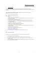
AAM6020VI-T4 User Manual 1. Introduction Congratulations on becoming the owner of an ASUS AAM6020VI-T4 CPE (Customer Premises Equipment). Your LAN (Local Area Network) will now be able to access the Internet via the CPE’s ADSL connection. This User Manual will show you how to set up the AAM6020VI-T4 CPE, and how to customize its configuration to get the most out of this product. 1.
AAM6020VI-T4 User Manual 2. Your CPE at a glance Your CPE has many ports, switches and LEDs. Let’s take a look at the different options. Depending upon your model of CPE, your CPE may have some or all of the features listed below 2.1 Ports and buttons (Back panel) Power is where you connect the power. LAN 1~4 (local area network) port: connect to Ethernet network devices, such as a PC, hub, switch, or router. Some CPEs come with a single LAN connection and some come with four LAN connections.
AAM6020VI-T4 User Manual 2.3 LED table & parts list LED Table The LEDs can help diagnose problems.
AAM6020VI-T4 User Manual 3. Getting Start This chapter provides basic instructions for connecting the CPE to a computer or a LAN and to the Internet via ADSL. Part 1 provides instructions to set up the hardware. Part 2 describes how to configure Internet properties on your computer(s). Part 3 shows you how to access your CPE. It is assumed that you have already subscribed to ADSL service with your telephone company or other Internet service provider (ISP).
AAM6020VI-T4 User Manual 3.2 Configuring Your PC Before you start to access the CPE via Ethernet, you must configure your PC’s TCP/IP address to be 192.168.1.x, where x is any number between 2 and 254. The subnet mask must be 255.255.255.0. Your CPE’s default IP address is 192.168.1.1. If you use Ethernet cable to connect your AAM6020VI-T4 and PC, you don’t need any specific driver installation. 3.2.1 Windows XP: 1. In the Windows task bar, click on the Start button, and then click on Control Panel.
AAM6020VI-T4 User Manual The Local Area Connection Properties dialog box is displayed with a list of currently installed network components. If the list includes Internet Protocol (TCP/IP), the protocol has already been enabled, in which case you can skip to Step 10. 4. If Internet Protocol (TCP/IP) does not appear as an installed component, click on . 5. In the Select Network Component Type dialog box, select Protocol, and then click on . 6.
AAM6020VI-T4 User Manual 8. If prompted, click on to restart your computer with the new settings. 9. After restarting your PC, double-click on the Network and Dial-up Connections icon in the Control Panel. 10. In Network and Dial-up Connections window, right-click on the Network icon, and then select Properties. . 11. In the Network Properties dialog box, select TCP/IP, and then click on 12.
AAM6020VI-T4 User Manual 3.2.5 Windows NT 4.0: 1. In the Windows NT task bar, click on the Start button, point to Settings, and then click Control Panel. 2. In the Control Panel window, double click on the Network icon. 3. In the Network dialog box, click on the Protocols tab. The Protocols tab displays a list of currently installed network protocols. If the list includes TCP/IP, the protocol has already been enabled, in which case you can skip to Step 9. . 4.
AAM6020VI-T4 User Manual 4. Setting up your CPE This section will guide you through your CPE’s configuration. The CPE is shipped with a standard default bridge configuration; for most users, you may want to change the CPE from a bridge to a router. 4.1 Log into your CPE To configure your CPE, open your web browser. You may get an error message at this point; this is normal. Don’t panic. Continue following these directions. Type the default IP address (192.168.1.
AAM6020VI-T4 User Manual Figure 2 (Home page) 4.3 Setup To setup your CPE with a basic configuration, from the Home page, select Setup. Figure 3 illustrates the setup page. The page is broken into two subsections the WAN configuration and the LAN configuration. Before configuring the router, there are several concepts that you should be familiar with on how your new router works. Please take a moment to familiarize yourself with these concepts, as it should make the configuration much easier.
AAM6020VI-T4 User Manual 4.3.2 Local Area Network connection On one side of your router, you have your own Local Area network (LAN) connections. This is where you plug in your local computers to the router. The router is normally configured to automatically provide all the PC's on your network with Internet addresses. 4.4 Configuring the WAN Before the CPE will pass any data between the LAN interface(s) and the WAN interface, the WAN side of the modem must be configured.
AAM6020VI-T4 User Manual Figure 4 (Bridge Connection Setup) To complete the connection you must now click the apply button. The apply button will temporarily save this connection. To make the change permanent you need to click on Tools (at the top of the page) and select System Commands. At the system commands page, click on Save All. 4.4.1.2 PPPoA Connection Setup PPPoA is also known as RFC 2364. It is a method of encapsulating PPP packets over ATM cells which are carried over the DSL line.
AAM6020VI-T4 User Manual e. f. g. h. Keep Alive: When on-demand option is not enable, this value specifies the time to wait without being connected to your provider before terminating the connection. To ensure that the link is always active, enter a 0 in this field. Set Route: Specify this connection as the default-route. MRU: Maximum Receive Unit the DSL connection can receive. It is a negotiated value that asks the provider to send packets of no more than n bytes.
AAM6020VI-T4 User Manual b. c. d. e. f. g. h. i. Password: The password for the PPPoE access; this is provided by your DSL service provider or your ISP. On-Demand: Enables on-demand mode. The connection will disconnect if no activity is detected after the specified idle timeout value. Idle Timeout: Specifies that PPPoE connection should disconnect if the link has no activity detected for n seconds. This field is used in conjunction with the On-Demand feature.
AAM6020VI-T4 User Manual setup page is displayed; figure 7 illustrates a typical DHCP configuration. Give your DHCP connection a unique name; the name must not have spaces and cannot begin with numbers. In this case the unique name is called DHCP1. Select the encapsulation type (LLC or VC); if you are not sure just use the default mode. Select the VPI and VCI settings; your DSL service provider or your ISP will supply these; in this case the DSL service provider is using 0,35.
AAM6020VI-T4 User Manual you can also select a bridge connection or a routed connection. Since static IP address is typically used to host WEB servers, you may want to use a bridge connection. Figure 8 (Static IP Connection Setup) To complete the connection you must now click the apply button. The apply button will temporarily save this connection. To make the change permanent you need to click on Tools (at the top of the page) and select System Commands. At the system commands page, click on Save All. 4.
AAM6020VI-T4 User Manual The Start IP Address is where the DHCP server starts issuing IP addresses and the End IP Address is where the DHCP server stops issuing IP addresses. The Lease Time is the amount of time a network user will be allowed connection to the Router with their current dynamic IP address. The amount of time is in units of minutes; the default value is 3600 sec (60 minutes).
AAM6020VI-T4 User Manual Figure 10 (Example of a DHCP Relay configuration) By turning off the DHCP server and relay the network administrator must carefully configure the IP address, Subnet Mask and DNS settings of every computer on your network. Do not assign the same IP address to more than one computer and your CPE must be on the same subnet as all the other computers. The apply button will temporarily save this connection.
AAM6020VI-T4 User Manual 4.5.3 Firewall/NAT Services You can enable or disable Firewall and NAT by going to the Home screen, click setup and under LAN Setup, select Firewall/NAT Services. By unselecting the “Enable Firewall and NAT Services” button the firewall and NAT services is disabled for all WAN connections. The apply button will temporarily save this connection. To make the change permanent you need to click on Tools (at the top of the page) and select System Commands.
AAM6020VI-T4 User Manual 4.6.1 UPnP UPnP NAT and Firewall Traversal allow traffic to pass-thru the router for applications using the UPnP protocol. This feature requires one active DSL connection. In presence of multiple DSL connections, select the one over which the incoming traffic will be present, for example the default Internet connection. To enable UPnP, you must first have a WAN connection configured.
AAM6020VI-T4 User Manual 4.6.2 Port Forwarding Using the Port Forwarding page, you can provide local services (for example web hosting) for people on the Internet or play Internet games. When users send this type of request to your network via the Internet, the Router will forward those requests to the appropriate PC. Port forwarding can be used with DHCP assigned addresses but remember that a DHCP address is dynamic (not static).
AAM6020VI-T4 User Manual Figure 13 (Port Forwarding & Netmeeting) The apply button will temporarily save this connection. To make the change permanent you need to click on Tools (at the top of the page) and select System Commands. At the system commands page, click on Save All. 4.6.3 IP QoS/IP filters The QoS setup page allows you to configure IP QoS for a connection, to view the configured QoS rules and to add/delete a QoS rule.
AAM6020VI-T4 User Manual Figure 14 (IP QoS) IP Filters This firewall feature allows you to block network access based on a user's computer IP address. You can use this page to block specific traffic (for example block web access) or any traffic from a computer on your local network. To configure an IP Filter rule select the computers' IP address and add the corresponding firewall traffic definition from the Firewall Policy Database.
AAM6020VI-T4 User Manual which are part of the bridge itself. Twenty filter rules are supported with bridge filtering. To enable Bridge Filters, from the Home screen, click Advanced and under Advanced, select Bridge Filters. Figure 15 illustrates a typical Bridge filter configuration. The User Interface for Bridge Filter allows the user to add/edit/delete, as well as, enables the filter rules.
AAM6020VI-T4 User Manual a. Anyone can join or leave a host group at will. b. There are no restrictions on a host's location. c. There are no restrictions on the number of members that may belong to a host group. d. A host may belong to multiple host groups. e. Non-group members may send UDP datagrams to the host group. Multicasting is useful when data needs to be sent to more than one other device.
AAM6020VI-T4 User Manual Figure 17 (Static Routing) The apply button will temporarily save this connection. To make the change permanent you need to click on Tools (at the top of the page) and select System Commands. At the system commands page, click on Save All. 4.6.9 Dynamic Routing Dynamic Routing allows the CPE to automatically adjust to physical changes in the network.
AAM6020VI-T4 User Manual Figure 18 (Dynamic Routing) The apply button will temporarily save this connection. To make the change permanent you need to click on Tools (at the top of the page) and select System Commands. At the system commands page, click on Save All.
AAM6020VI-T4 User Manual 4.7 Wireless This section will guide you through your CPE’s Wireless configuration. The CPE is shipped with a default AP (Access Point) enable; you must restart AP for Wireless changes to take effect. 4.7.1 Setup The CPE has it default SSID named “ADSL_Wireless” you can redefine this field, the SSID is a unique name to identify the CPE in the Wireless LAN. Wireless stations associating to the CPE must have the same SSID.
AAM6020VI-T4 User Manual 4.7.2 Configuration The configuration field provides detail Wireless channel parameters adjusting. Figure 20 (Wireless Configuration) The RTS Threshold is the data with its frame size larger than this value will perform the handshake. Setting this attribute to be larger than the maximum MSDU (MAC service data unit) size turns off the RTS handshake. Setting this attribute to zero turns on the RTS handshake. Enter a value between 0 and 2432.
AAM6020VI-T4 User Manual The WEP encryption scrambles the data transmitted between the wireless stations and the access points to keep network communications private. It encrypts unicast and multicast communications in a network. Both the wireless stations and the access points must use the same WEP key for data encryption and decryption. Your CPE allows you to configure up to four 64-bit, 128-bit, or 256-bit WEP keys but only one key can be enabled at any one time.
AAM6020VI-T4 User Manual 4.8 Tools The CPE supports a host of tools which will allow you to customize and debug your CPE. 4.8.1 System Commands To make the changes permanent you need to click on Tools (at the top of the page) and select System Commands. The following commands are used to configure the CPE: a. Save all: Press this button in order to permanently save the current configuration of the CPE.
AAM6020VI-T4 User Manual The apply button will temporarily save this connection. To make the change permanent you need to click on Tools (at the top of the page) and select System Commands. At the system commands page, click on Save All. 4.8.4 Update Gateway You can remotely upgrade the CPE’s firmware by going to the Home screen, under the tools title, click Update Gateway. This will bring up the screen shown in Figure 19.
AAM6020VI-T4 User Manual Figure 24 (Ping test) 4.8.6 Modem Test The Modem Test is used to check whether your Modem is properly connected to the WAN Network. This test may take a few seconds to complete. To perform the test, select your connection from the list and press the Test button. Before running this test, make sure you have a valid DSL link; if the DSL link is not connected, this test will always fail. Also the DSLAM must support this feature; not all DSLAMs have F4 and F5 support. 4.
AAM6020VI-T4 User Manual Figure 25 (Product Information) 4.9.6 System Log You can display the CPE’s log by going to the Home screen, under the Status title, click System log. From here you can view all logged information. Depending upon the severity level, this logged info will generate log reports to a remote host (if remote logging is enabled).
AAM6020VI-T4 User Manual 5. Appendix A: Troubleshooting Below is a list of commonly asked questions. Before calling technical support, please look through these issues to see if they help solve your problem. 5.1 The CPE is not functional 1. 2. 3. 4. 5. 6. 7. 8. 9. 5.2 I can’t connect to the CPE. 1. 2. 3. 4. 5. 6. 5.3 Check to see that the power LED is green and than the network cables are installed correctly. Refer to the quick start guide for more details.
AAM6020VI-T4 User Manual 5.4 The DSL Link LED continues to blink but does not go solid 1. This means that the DSL line is trying to train but for some reason it cannot establish a valid connection. The main cause of this is that you are too far away from the central office. Contact your DSL service provider for further assistance. Common Problems and Solutions 5.5 The DSL Link LED is always off 1. Make sure you have DSL service.
AAM6020VI-T4 User Manual 6. Router terms What is a firewall? A firewall is protection between the Internet and your local network. It acts similarly to the firewall in your car, protecting the interior of the car from the engine. Your car's firewall has very small opening that allow desired connections from the engine into the cabin (gas pedal connection, etc), but if something happens to your engine, you are protected. The firewall in the router is very similar.