Motherboard AM1M-A
E9004 First Edition January 2014 Copyright © 2014 ASUSTeK COMPUTER INC. All Rights Reserved. No part of this manual, including the products and software described in it, may be reproduced, transmitted, transcribed, stored in a retrieval system, or translated into any language in any form or by any means, except documentation kept by the purchaser for backup purposes, without the express written permission of ASUSTeK COMPUTER INC. (“ASUS”).
Contents Safety information....................................................................................... iv About this guide.......................................................................................... iv Package contents........................................................................................ vi AM1M-A specifications summary.............................................................. vi Chapter 1: Product introduction 1.1 Before you proceed......................
Safety information Electrical safety • • • • • • To prevent electrical shock hazard, disconnect the power cable from the electrical outlet before relocating the system. When adding or removing devices to or from the system, ensure that the power cables for the devices are unplugged before the signal cables are connected. If possible, disconnect all power cables from the existing system before you add a device.
Where to find more information Refer to the following sources for additional information and for product and software updates. 1. 2. ASUS websites The ASUS website provides updated information on ASUS hardware and software products. Refer to the ASUS contact information. Optional documentation Your product package may include optional documentation, such as warranty flyers, that may have been added by your dealer. These documents are not part of the standard package.
Package contents Check your motherboard package for the following items. Motherboard ASUS AM1M-A motherboard Cables 2 x Serial ATA 6.0 Gb/s cables Accessories 1 x I/O Shield Application DVD Support DVD Documentation User Guide If any of the above items is damaged or missing, contact your retailer. AM1M-A specifications summary APU Chipset Memory AMD® Sempron and Athlon Series processors Supports CPU up to 4 cores • Refer to www.asus.com for the AMD® APU support list.
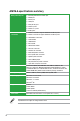
AM1M-A specifications summary Audio USB ASUS unique features Realtek® ALC887 8-channel High Definition Audio CODEC - Supports Jack-Detection, Multi-Streaming, Front Panel Retasking AMD® Sempron and Athlon Series APUs - 8 x USB 2.0 ports (4 ports at mid-board, 4 ports at the back panel) - 2 x USB 3.0 ports (2 ports at mid-board) ASMedia® ASM1042 Controller - 2 x USB 3.
AM1M-A specifications summary Back panel I/O ports 1 x PS/2 Keyboard/mouse combo port 1 x HDMI port 1 x DVI-D port 1 x VGA port 1 x LAN (RJ-45) port 2 x USB 3.0 ports 4 x USB 2.0/1.1 ports 3 x Audio jacks Internal I/O connectors 1 x USB 3.0 connector supports additional 2 USB 3.0 ports 2 x USB 2.0 connectors support additional 4 USB 2.
Product introduction 1.1 Before you proceed 1 Take note of the following precautions before you install motherboard components or change any motherboard settings. • Unplug the power cord from the wall socket before touching any component. • Before handling components, use a grounded wrist strap or touch a safely grounded object or a metal object, such as the power supply case, to avoid damaging them due to static electricity. • Hold components by the edges to avoid touching the ICs on them.
1.2 Motherboard overview Before you install the motherboard, study the configuration of your chassis to ensure that the motherboard fits. Unplug the power cord before installing or removing the motherboard. Failure to do so can cause you physical injury and damage to motherboard components. 1.2.1 Placement direction When installing the motherboard, place it into the chassis in the correct orientation. The edge with external ports goes to the rear part of the chassis as indicated in the image. 1.2.
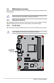
1.2.3 Motherboard layout 1 2 3 1 4 17.0cm(6.7in) CPU_FAN KBMS_USB34 DIGI +VRM ATX12V 64Mb BIOS CHA_FAN USB3_12 AUDIO 22.6cm(8.
1.2.4 Layout contents Connectors/Jumpers/Slots/LED 1. CPU and chassis fan connectors (4-pin CPU_FAN, and 4-pin CHA_FAN) 2. AMD AM1 socket 3. ATX power connectors (24-pin EATXPWR, 4-pin ATX12V) 4. DDR3 DIMM slots 5. SATA 6.0 Gb/s connectors (7-pin SATA6G_1~2) 6. Clear RTC RAM (3-pin CLRTC) 7. Standby power LED (SB_PWR) 8. Speaker connector (4-pin SPEAKER) 9. System panel connector (10-1 pin F_PANEL) 10. TPM connector (20-1 pin TPM) 11. USB 2.0 connectors (10-1 pin USB56, USB78) 12.
1.3.
1.3.2 APU heatsink and fan assembly installation Apply the Thermal Interface Material to the APU heatsink and APU before you install the heatsink and fan if necessary.
To uninstall the APU heatsink and fan assembly 1 2 3 ASUS AM1M-A 1-7
1.4 1.4.1 System memory Overview This motherboard comes with two Double Data Rate 3 (DDR3) Single Inline Memory Modules (DIMM) sockets. A DDR3 module has the same physical dimensions as a DDR2 DIMM but is notched differently to prevent installation on a DDR2 DIMM socket. DDR3 modules are developed for better performance with less power consumption.
1.4.3 • The default memory operation frequency is dependent on its Serial Presence Detect (SPD), which is the standard way of accessing information from a memory module. Under the default state, some memory modules for overclocking may operate at a lower frequency than the vendor-marked value. To operate at the vendor-marked or at a higher frequency, refer to section 2.5 Ai Tweaker menu for manual memory frequency adjustment.
To remove a DIMM B A A 1.5 Expansion slots In the future, you may need to install expansion cards. The following sub‑sections describe the slots and the expansion cards that they support. Unplug the power cord before adding or removing expansion cards. Failure to do so may cause you physical injury and damage motherboard components. 1.5.1 Installing an expansion card To install an expansion card: 1.
1.5.3 PCI Express 2.0 x1 slots This motherboard supports PCI Express x1 network cards, SCSI cards, and other cards that comply with the PCI Express specifications. 1.5.4 PCI Express x16 slot This motherboard supports PCI Express x16 (running @ x4) network cards, SCSI cards, and other cards that comply with the PCI Express specifications.
1.6 1. Jumpers Clear RTC RAM (3-pin CLRTC) This jumper allows you to clear the Real Time Clock (RTC) RAM in CMOS. You can clear the CMOS memory of date, time, and system setup parameters by erasing the CMOS RTC RAM data. The onboard button cell battery powers the RAM data in CMOS, which include system setup information such as system passwords. 1 2 CLRTC 2 3 AM1M-A Normal (Default) Clear RTC AM1M-A Clear RTC RAM To erase the RTC RAM: 1. Turn OFF the computer and unplug the power cord. 2.
1.7 Connectors 1.7.1 Rear panel connectors 1 2 8 3 10 4 9 5 6 8 7 1. PS/2 Keyboard/Mouse Combo port. This port is for a PS/2 keyboard/mouse. 2. HDMI port. This port is for a High-Definition Multimedia Interface (HDMI) connector, and is HDCP compliant allowing playback of HD DVD, Blu-ray, and other protected content. 3. Video Graphics Adapter (VGA) port. This 15-pin port is for a VGA monitor or other VGA-compatible devices. 4. LAN (RJ-45) port.
Audio 2.1, 4.1, 5.1, or .1-channel configuration Headset 2.1-channel Port Light Blue (Rear panel) Line In Lime (Rear panel) Line Out Pink (Rear panel) Lime (Front panel) Mic In — 4.1-channel 5.1-channel Rear Speaker Out Front Speaker Out Mic In — Rear Speaker Out Front Speaker Out Bass/Center — 7.1-channel Rear Speaker Out Front Speaker Out Bass/Center Side Speaker Out To configure a 7.1-channel audio output: Use a chassis with HD audio module in the front panel to support a 7.
1.7.2 1. Internal connectors CPU and chassis fan connectors (4-pin CPU_FAN, and 4-pin CHA_FAN) Connect the fan cables to the fan connectors on the motherboard, ensuring that the black wire of each cable matches the ground pin of the connector. VCC CPU FAN IN CPU FAN PWR GND CPU_FAN AM1M-A VCC CHA FAN IN CHA FAN PWR GND CHA_FAN AM1M-A Fan connectors DO NOT forget to connect the fan cables to the fan connectors. Insufficient air flow inside the system may damage the motherboard components.
2. ATX power connectors (24-pin EATXPWR, 4-pin ATX12V) These connectors are for an ATX power supply. The plugs from the power supply are designed to fit these connectors in only one orientation. Find the proper orientation and push down firmly until the connectors completely fit.
3. Serial ATA 6.0 Gb/s connectors (7-pin SATA6G 1~2) These connectors are for the Serial ATA 6.0 Gb/s signal cables for Serial ATA hard disk drives and optical disc drives. SATA6G_2 GND RSATA_TXP2 RSATA_TXN2 GND RSATA_RXN2 RSATA_RXP2 GND SATA6G_1 AM1M-A GND RSATA_TXP1 RSATA_TXN1 GND RSATA_RXN1 RSATA_RXP1 GND AM1M-A SATA 6.0Gb/s connectors 4. • These connectors are set to AHCI mode by default.
5. System panel connector (10-1 pin PANEL) This connector supports several chassis-mounted functions. F_PANEL PWR_LED+ PWR_LEDPWR GND +PWR LED PWR BTN HDD_LED+ HDD_LEDGround HWRST# (NC) PIN 1 AM1M-A +HDD_LED RESET AM1M-A System panel connector • • • • 6. System power LED (2-pin PLED) This 2-pin connector is for the system power LED. Connect the chassis power LED cable to this connector.
Digital audio connector (4-1 pin SPDIF_OUT) SPDIFOUT GND This connector is for an additional Sony/Philips Digital Interface (S/PDIF) port. +5V 7. AM1M-A SPDIF_OUT AM1M-A Digital audio connector The S/PDIF module is purchased separately.
9. USB 2.0 connectors (10-1 pin USB56, USB78) These connectors are for USB 2.0 ports. Connect the USB module cable to any of these connectors, then install the module to a slot opening at the back of the system chassis. These USB connectors comply with USB 2.0 specification that supports up to 480Mbps connection speed. PIN 1 USB+5V USB_P6USB_P6+ GND AM1M-A USB+5V USB_P7USB_P7+ GND NC USB78 PIN 1 USB+5V USB_P8USB_P8+ GND USB+5V USB_P5USB_P5+ GND NC USB56 AM1M-A USB2.
11. Serial port connector (10-1 pin COM) This connector is for a serial (COM) port. Connect the serial port module cable to this connector, then install the module to a slot opening at the back of the system chassis. RXD DTR DSR CTS COM DCD TXD GN D RTS RI PIN 1 AM1M-A AM1M-A Serial port connectors The COM module is purchased separately. 12. LPT connector (26-1 pin LPT) The LPT (Line Printing Terminal) connector supports devices such as a printer.
1.8 1.8.1 Software support Installing an operating system This motherboard supports Windows® XP / Windows® 7 / 64-bit Windows® 7 / Windows® 8 / 64-bit Windows® 8 / Windows® 8.1 / 64-bit Windows® 8.1 Operating Systems (OS). Always install the latest OS version and corresponding updates to maximize the features of your hardware. 1.8.2 • Motherboard settings and hardware options vary. Refer to your OS documentation for detailed information.
BIOS information 2.1 Managing and updating your BIOS 2 Save a copy of the original motherboard BIOS file to a USB flash disk in case you need to restore the BIOS in the future. Copy the original motherboard BIOS using the ASUS Update utility. 2.1.1 EZ Update EZ Update is a utility that allows you to automatically update your motherboard’s softwares, drivers and the BIOS version easily. With this utlity, you can also manually update the saved BIOS and select a boot logo when the system goes into POST.
2.1.2 ASUS EZ Flash 2 The ASUS EZ Flash 2 feature allows you to update the BIOS without using an OS‑based utility. Before you start using this utility, download the latest BIOS file from the ASUS website at www.asus.com. To update the BIOS using EZ Flash 2: 2-2 1. Insert the USB flash disk that contains the latest BIOS file to the USB port. 2. Enter the Advanced Mode of the BIOS setup program. Go to the Tool menu to select ASUS EZ Flash Utility and press to enable it. 3.
2.1.3 ASUS CrashFree BIOS 3 utility The ASUS CrashFree BIOS 3 is an auto recovery tool that allows you to restore the BIOS file when it fails or gets corrupted during the updating process. You can restore a corrupted BIOS file using the motherboard support DVD or a USB flash drive that contains the updated BIOS file. • Before using this utility, rename the BIOS file in the removable device into AM1M-A.CAP. • The BIOS file in the support DVD may not be the latest version.
Booting the system to a DOS environment 1. Insert the USB flash drive with the latest BIOS file and BIOS Updater to the USB port. 2. Boot your computer. When the ASUS Logo appears, press to show the BIOS Boot Device Select Menu. Insert the support DVD into the optical drive and select the optical drive as the boot device. 3. When the Make Disk menu appears, select the FreeDOS command prompt item by pressing the item number. 4.
3. Press to switch between screen fields and use the keys to select the BIOS file and press . BIOS Updater checks the selected BIOS file and prompts you to confirm BIOS update. 4. Select Yes and press . When BIOS update is done, press to exit BIOS Updater. Restart your computer. DO NOT shut down or reset the system while updating the BIOS to prevent system boot failure! • For BIOS Updater version 1.
2.2 BIOS setup program Use the BIOS Setup program to update the BIOS or configure its parameters. The BIOS screens include navigation keys and brief online help to guide you in using the BIOS Setup program. Entering BIOS Setup at startup To enter BIOS Setup at startup: • Press during the Power-On Self Test (POST). If you do not press , POST continues with its routines. Entering BIOS Setup after POST To enter BIOS Setup after POST: • Press ++ simultaneously.
EZ Mode By default, the EZ Mode screen appears when you enter the BIOS setup program. The EZ Mode provides you an overview of the basic system information, and allows you to select the display language, system performance mode and boot device priority. To access the Advanced Mode, click Exit/Advanced Mode, then select Advanced Mode or press F7 for the advanced BIOS settings. The default screen for entering the BIOS setup program can be changed. Refer to the Setup Mode item in section 2.
Advanced Mode The Advanced Mode provides advanced options for experienced end-users to configure the BIOS settings. The figure below shows an example of the Advanced Mode. Refer to the following sections for the detailed configurations. To access the EZ Mode, click Exit, then select ASUS EZ Mode or press F7.
Back button This button appears when entering a submenu. Press or use the USB mouse to click this button to return to the previous menu screen. Submenu items A greater than sign (>) before each item on any menu screen means that the item has a submenu. To display the submenu, select the item and press . Pop-up window Select a menu item and press to display a pop-up window with the configuration options for that item.
2.3 My Favorites MyFavorites is your personal space where you can easily save and access your favorite BIOS items. Adding items to My Favorites To add frequently-used BIOS items to My Favorites: 1. Use the arrow keys to select an item that you want to add. When using a mouse, hover the pointer to the item. 2. Press on your keyboard or right-click on your mouse to add the item to My Favorites page.
2.4 Main menu 2.4.1 System Language [English] The Main menu screen appears when you enter the Advanced Mode of the BIOS Setup program. The Main menu provides you an overview of the basic system information, and allows you to set the system date, time, language, and security settings. Allows you to choose the BIOS language version from the options. Configuration options: [English] [Español] [Русский] 2.4.2 System Date [Day xx/xx/xxxx] Allows you to set the system date. 2.4.
Administrator Password If you have set an administrator password, we recommend that you enter the administrator password for accessing the system. Otherwise, you might be able to see or change only selected fields in the BIOS setup program. To set an administrator password: 1. Select the Administrator Password item and press . 2. From the Create New Password box, key in a password, then press . 3. Confirm the password when prompted. To change an administrator password: 1.
2.5 Ai Tweaker menu The Ai Tweaker menu items allow you to configure overclocking-related items. Be cautious when changing the settings of the Ai Tweaker menu items. Incorrect field values can cause the system to malfunction. The configuration options for this section vary depending on the CPU and DIMM model you installed on the motherboard. Target CPU Speed : xxxxMHz Displays the current CPU speed. Target DRAM Speed : xxxxMHz Displays the current DRAM speed. 2.5.
2.5.2 Memory Frequency [Auto] Allows you to set the memory operating frequency. Configuration options: [Auto] [DDR3800MHz] [DDR3-1066MHz] [DDR3-1333MHz] [DDR3-1600MHz] ] Selecting a very high memory frequency may cause the system to become unstable! If this happens, revert to the default setting. 2.5.3 APU Multiplier [Auto] Allows you to set the multiplier between the APU Core Clock and the APU Bus Frequency. Use the <+> and <-> keys to adjust the multiplier.
CPU Offset Voltage [Auto] Allows you to set the CPU Offset voltage. The values range from 0.00625V to 0.4000V with a 0.01000V interval. Refer to the CPU documentation before setting the CPU voltage. Setting a high voltage may damage the CPU permanently, and setting a low voltage may make the system unstable. VDDNB Offset Mode Sign [+] [+] [–] To offset the voltage by a positive value. To offset the voltage by a negative value. VDDNB Offset Voltage [Auto] Allows you to set the VDDNB Offset voltage.
CPU Current Capability [100%] This item provides wider total power range for overclocking. A higher value brings a wider total power range and extends the overclocking frequency range simultaneously. Configuration options: [100%] [110%] [120%] [130%] CPU/NB Current Capability [100%] This item provides wider total power range for overclocking. A higher value brings a wider total power range and extends the overclocking frequency range simultaneously.
AMD PowerNow function [Enabled] Enables or disables the AMD PowerNow function. Configuration options: [Enabled] [Disabled] NX Mode [Enabled] Enables or disables the No-execute page protection function. Configuration options: [Enabled] [Disabled] SVM Mode [Enabled] Enables or disables CPU virtualization. Configuration options: [Disabled] [Enabled] C6 Mode [Enabled] Enables or disables C6 mode.
2.6.3 USB Configuration The items in this menu allow you to change the USB-related features. The USB Devices item shows the auto-detected values. If no USB device is detected, the item shows None. Enabled All of USB Devices [Enabled] Allows you to enable or disable all USB ports. Configuration options: [Disabled] [Enabled] Legacy USB Support [Enabled] [Enabled] [Disabled] [Auto] Enables the support for USB devices on legacy operating systems (OS).
2.6.5 Onboard Devices Configuration HD Audio Azalia Device [Enabled] [Enabled] [Disabled] Enables the High Definition Audio Controller. Disables the controller. The following item appears only when you set the HD Audio Azalia Device item to [Enabled]. Azalia Front Panel [HD] Allows you to set the front panel audio connector (AAFP) mode to legacy AC’97 or highdefinition audio depending on the audio standard that the front panel audio module supports.
Change Settings [IO=3F8h; IRQ=4] This item appears only when you set the Serial Port to [Enabled] and allows you to select the Serial Port base address. Configuration options: [IO=3F8h; IRQ=4] [IO=2F8h; IRQ=3] [IO=3E8h; IRQ=4] [IO=2E8h; IRQ=3] Parallel Port Configuration The sub-items in this menu allow you to set the parallel port configuration. Parallel Port [Enabled] Allows you to enable or disable the parallel port (LPT).
Power On By RTC [Disabled] [Disabled] [Enabled] 2.6.7 Disables RTC to generate a wake event. When set to [Enabled], the items RTC Alarm Date (Days) and Hour/ Minute/Second will become user-configurable with set values. Network Stack Network Stack [Disabled] This item allows user to disable or enable the UEFI network stack. Configuration options: [Disabled] [Enabled] The following two items appear only when you set the previous item to [Enabled].
2.7 Monitor menu The Monitor menu displays the system temperature/power status, and allows you to change the fan settings. Scroll down to display the other items. 2.7.1 CPU Temperature / MB Temperature [xxxºC/xxxºF] The onboard hardware monitor automatically detects and displays the CPU and motherboard temperatures. Select Ignore if you do not wish to display the detected temperatures. 2.7.
Q-Fan Profile [Standard] This item appears when you set CPU Q-Fan Control to [PWM Mode] or [DC Mode] and allows you to set the appropriate performance level of the CPU fan. [Standard] Sets to [Standard] to make the CPU fan automatically adjust depending on the CPU temperature. [Silent] Sets to [Silent] to minimize the fan speed for quiet CPU fan operation. [Turbo] [Manual] Sets to [Turbo] to achieve maximum CPU fan speed. Sets to [Manual] to assign detailed fan speed control parameters.
The following four items appear only when you set Q-Fan Profile to [Manual]. Q-Fan Upper Temperature [70] Use the <+> and <-> keys to adjust the upper limit of the chassis temperature. The values range from 40ºC to 75ºC. Q-Fan Max. Duty Cycle(%) [100] Use the <+> and <-> keys to adjust the maximum chassis fan duty cycle. The values range from 60% to 100%. When the chassis temperature reaches the upper limit, the chassis fan will operate at the maximum duty cycle.
2.8 Boot menu The Boot menu items allow you to change the system boot options. Scroll down to display the other items. 2.8.1 Fast Boot [Enabled] [Enabled] Select to accelerate the boot speed. [Disabled] Select to go back to normal boot. The following five items appear when you set Fast Boot to [Enabled]. SATA Support [All Devices] [All Devices] All devices connected to the SATA ports will be available during POST. This process will extend the POST time.
USB Support [Partial Initialization] [Disabled] All USB devices will not be available until OS boot up for a fastest POST time. [Full Initialization] All USB devices will be available during POST. This process will extend the POST time. [Partial Initialization] For a faster POST time, only the USB ports with keyboard and mouse connections will be detected. PS/2 Keyboard and Mouse Support [Auto] Select any of these settings when PS/2 keyboard and mouse are installed.
2.8.3 Bootup NumLock State [On] [On] Sets the power-on state of the NumLock to [On]. [Off] 2.8.4 Sets the power-on state of the NumLock to [Off]. Wait for ‘F1’ If Error [Enabled] When this item is set to [Enabled], the system waits for the F1 key to be pressed when error occurs. Configuration options: [Disabled] [Enabled] 2.8.5 Option ROM Messages [Force BIOS] [Force BIOS] [Keep Current] 2.8.
Boot from Network Devices [Legacy OpROM first] Allows you to select the type of network devices that you want to launch. Configuration options: [Legacy OpROM first] [UEFI driver first] [Ignore] Boot from Storage Devices [Legacy OpROM first] Allows you to select the type of storage devices that you want to launch.
PK Management The Platform Key (PK) locks and secures the firmware from any non-permissible changes. The system verifies the PK before your system enters the OS. Delete PK Allows you to delete the PK from your system. Once the PK is deleted, all the system’s Secure Boot keys will not be active. Configuration options: [Yes] [No] Load PK from File Allows you to load the downloaded PK from a USB storage device.
DBX Management The dbx (Revoked Signature database) lists the forbidden images of db items that are no longer trusted and cannot be loaded. Delete the DBX Allows you to delete the DBX file from your system. Configuration options: [Yes] [No] Load DBX from File Allows you to load the downloaded DBX from a USB storage device. Append DBX from file Allows you to load the additional DBX from a storage device so that more db’s images cannot be loaded.
2.9 Tools menu 2.9.1 ASUS EZ Flash 2 Utility The Tools menu items allow you to configure options for special functions. Select an item then press to display the submenu. Allows you to run ASUS EZ Flash 2. Press [Enter] to launch the ASUS EZ Flash 2 screen. For more details, see section 2.1.2 ASUS EZ Flash 2. 2.9.2 ASUS O.C. Profile This item allows you to store or load multiple BIOS settings. The Setup Profile Status items show Not Installed if no profile is created.
2.9.3 ASUS SPD Information DIMM Slot # [DIMM_A1] Displays the Serial Presence Detect (SPD) information of the DIMM module installed on the selected slot. Configuration options: [DIMM_A1] [DIMM_A2] 2.10 Exit menu The Exit menu items allow you to load the optimal default values for the BIOS items, and save or discard your changes to the BIOS items. You can access the EZ Mode from the Exit menu.
Appendices Notices Federal Communications Commission Statement This device complies with Part 15 of the FCC Rules. Operation is subject to the following two conditions: • • This device may not cause harmful interference. This device must accept any interference received including interference that may cause undesired operation. This equipment has been tested and found to comply with the limits for a Class B digital device, pursuant to Part 15 of the FCC Rules.
Canadian Department of Communications Statement This digital apparatus does not exceed the Class B limits for radio noise emissions from digital apparatus set out in the Radio Interference Regulations of the Canadian Department of Communications. This class B digital apparatus complies with Canadian ICES-003.
ASUS contact information ASUSTeK COMPUTER INC. Address Telephone Fax E-mail Web site Technical Support Telephone Online support 15 Li-Te Road, Peitou, Taipei, Taiwan 11259 +886-2-2894-3447 +886-2-2890-7798 info@asus.com.tw www.asus.com.tw +86-21-38429911 support.asus.
A-4 Appendices (510)739-3777/(510)608-4555 800 Corporate Way, Fremont, CA 94539. Asus Computer International Date : Signature : Representative Person’s Name : Feb. 24, 2014 Steve Chang / President This device complies with part 15 of the FCC Rules. Operation is subject to the following two conditions: (1) This device may not cause harmful interference, and (2) this device must accept any interference received, including interference that may cause undesired operation.