• C8HM70-I • C8HM70-I/HDMI Motherboard C8HM70-I SERIES
E7848 First Edition November 2012 Copyright © 2012 ASUSTeK COMPUTER INC. All Rights Reserved. No part of this manual, including the products and software described in it, may be reproduced, transmitted, transcribed, stored in a retrieval system, or translated into any language in any form or by any means, except documentation kept by the purchaser for backup purposes, without the express written permission of ASUSTeK COMPUTER INC. (“ASUS”).
Contents Safety information........................................................................................................ v About this guide.......................................................................................................... vi C8HM70-I SERIES specifications summary............................................................ viii Package contents.........................................................................................................
2.4 Ai Tweaker menu......................................................................................... 2-12 2.4.1 Memory Frequency [Auto].............................................................. 2-12 2.4.3 CPU Power Management.............................................................. 2-13 2.4.2 2.5 Advanced menu........................................................................................... 2-14 2.5.1 CPU Configuration.........................................................
Safety information Electrical safety • • • • • • To prevent electrical shock hazard, disconnect the power cable from the electrical outlet before relocating the system. When adding or removing devices to or from the system, ensure that the power cables for the devices are unplugged before the signal cables are connected. If possible, disconnect all power cables from the existing system before you add a device.
About this guide This user guide contains the information you need when installing and configuring the motherboard. How this guide is organized This guide contains the following parts: • • Chapter 1: Product introduction This chapter describes the features of the motherboard and the new technology it supports. Chapter 2: BIOS information This chapter tells how to change system settings through the BIOS Setup menus. Detailed descriptions of the BIOS parameters are also provided.
Conventions used in this guide To ensure that you perform certain tasks properly, take note of the following symbols used throughout this manual. DANGER/WARNING: Information to prevent injury to yourself when completing a task. CAUTION: Information to prevent damage to the components when completing a task IMPORTANT: Instructions that you MUST follow to complete a task. . NOTE: Tips and additional information to help you complete a task. Typography Bold text Indicates a menu or an item to select.
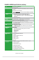
C8HM70-I SERIES specifications summary CPU Intel® Celeron® 847 (BGA1023) Memory 2 x SODIMM, max. 16GB, DDR3 1333/1066 MHz, non-ECC, un-buffered memory Chipset Intel® HM70 chipset Dual-channel memory architecture • Refer to www.asus.com or the user manual for Memory QVL (Qualify Vendor List) Graphics Integrated Graphics Processor- Intel® HD Graphics support - Supports D-sub with Max. resolution of 2048x1536@75 Hz - Supports HDMI with Max.
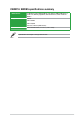
C8HM70-I SERIES specifications summary BIOS features Support DVD 64 Mb Flash ROM, UEFI AMI BIOS, PnP, DMI2.0, WfM2.0,SM BIOS 2.7, ACPI 2.0a, Multi-language BIOS, ASUS EZ Flash 2, ASUS CrashFree BIOS 3 Drivers ASUS utilities ASUS Update Form factor Anti-virus software (OEM version) Mini ITX Form Factor, 6.7” x 6.7” (17cm x 17cm) Specifications are subject to change without notice.
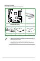
Package contents Check your motherboard package for the following items. KB_USB910 HDMI CPU_FAN Intel® VGA Celeron847 Intel® HM70 Super I/O DDR3 DIMM_A1 (64bit, 204-pin module) USB3_12 DDR3 DIMM_B1 (64bit 204-pin module) ATX12V CHA_FAN SATA6G_1 64Mb BIOS LAN_USB34 SATA3G_1 EATXPWR RTL 8111F USB1112 AUDIO AAFP ALC 887 Lithium Cell CMOS Power F_PANEL CLRTC C8HM70-I/HDMI SPEAKER CHASSIS SB_PWR PCIEX16_1 1 x Serial ATA 3.0 Gb/s cable 1 x Serial ATA 6.
Product introduction 1.1 Before you proceed 1 Take note of the following precautions before you install motherboard components or change any motherboard settings. • Unplug the power cord from the wall socket before touching any component. • Before handling components, use a grounded wrist strap or touch a safely grounded object or a metal object, such as the power supply case, to avoid damaging them due to static electricity. • Hold components by the edges to avoid touching the ICs on them.
1.2 Motherboard overview Before you install the motherboard, study the configuration of your chassis to ensure that the motherboard fits into it. Ensure that you unplug the power cord before installing or removing the motherboard. Failure to do so can cause you physical injury and damage motherboard components. C8HM70-I Series motherboards include C8HM70-I and C8HM70-I/HDMI models. The package contents vary from models. The layout illustrations in this user guide are for C8HM70-I/HDMI only. 1.2.
1.2.3 Motherboard layout 1 2 3 4 17.0cm(6.7in) KB_USB910 HDMI CPU_FAN Intel® VGA Celeron847 5 Intel® HM70 Super I/O 13 17.0cm(6.7in) CHA_FAN DDR3 DIMM_A1 (64bit, 204-pin module) USB3_12 DDR3 DIMM_B1 (64bit, 204-pin module) ATX12V SATA6G_1 64Mb BIOS LAN_USB34 SATA3G_1 2 EATXPWR RTL 8111F 12 USB1112 AUDIO AAFP Lithium Cell CMOS Power ALC 887 F_PANEL CLRTC C8HM70-I/HDMI SPEAKER CHASSIS SB_PWR PCIEX16_1 11 10 9 8 7 6 Following Intel’s specification, USB 2.
1.3 Central Processing Unit (CPU) The motherboard comes with an onboard Intel® Celeron™ 847 (BGA1023) processor and a specially designed CPU heatsink. Intel® Celeron847 C8HM70-I/HDMI C8HM70-I/HDMI CPU Celeron847 1.4 System memory 1.4.1 Overview DIMM_B1 DIMM_A1 This motherboard comes with two Double Data Rate 3 (DDR3) Small Outline Dual Inline Memory Modules (SO-DIMM) sockets.
C8HM70-I Series Motherboard Qualified Vendors Lists (QVL) DDR3-1333 MHz capability Vendors Part No. Size SS/ DS Chip Brand Chip No. CORSAIR CORSAIR G.SKILL G.
1.5 Expansion slots In the future, you may need to install expansion cards. The following sub‑sections describe the slots and the expansion cards that they support. Unplug the power cord before adding or removing expansion cards. Failure to do so may cause you physical injury and damage motherboard components. 1.5.1 Installing an expansion card To install an expansion card: 1.
1.6 Jumpers Clear RTC RAM (3-pin CLRTC) This jumper allows you to clear the Real Time Clock (RTC) RAM in CMOS. You can clear the CMOS memory of date, time, and system setup parameters by erasing the CMOS RTC RAM data. The onboard button cell battery powers the RAM data in CMOS, which include system setup information such as system passwords. 1 C8HM70-I/HDMI 2 CLRTC Normal (Default) 2 3 Clear RTC C8HM70-I/HDMI Clear RTC RAM To erase the RTC RAM: 1.
1.7 Connectors 1.7.1 1 Rear panel connectors 10 9 8 2 7 3 4 6 5 1. PS/2 Keyboard / Mouse Combo port. This port is for a PS/2 keyboard or PS/2 mouse. 2. LAN (RJ-45) port. This port allows Gigabit connection to a Local Area Network (LAN) through a network hub. Refer to the table below for the LAN port LED indications.
To configure an 8-channel audio output: Use a chassis with HD audio module in the front panel to support an 8-channel audio output. 6. USB 2.0 ports 3 and 4. These two 4-pin Universal Serial Bus (USB) ports are for USB 2.0/1.1 devices. 7. Video Graphics Adapter (VGA) port. This 15-pin port is for a VGA monitor or other VGA-compatible devices 8. HDMI port (C8HM70-I/HDMI only).
1.7.2 Internal connectors Front panel audio connector (10-1 pin AAFP) NC AGND NC NC SENSE2_RETUR This connector is for a chassis-mounted front panel audio I/O module that supports either HD Audio or legacy AC`97 audio standard. Connect one end of the front panel audio I/O module cable to this connector. AGND NC SENSE1_RETUR 1.
2. ATX power connectors (24-pin EATXPWR, 4-pin ATX12V) These connectors are for ATX power supply plugs. The power supply plugs are designed to fit these connectors in only one orientation. Find the proper orientation and push down firmly until the connectors completely fit.
4. CPU and chassis fan connectors (3-pin CPU_FAN, 4-pin CHA_FAN) Connect the fan cables to the fan connectors on the motherboard, ensuring that the black wire of each cable matches the ground pin of the connector. CHA_FAN GND CHA FAN PWR CHA FAN IN CHA FAN PWM CPU_FAN GND +12V Rotation C8HM70-I/HDMI C8HM70-I/HDMI CPU fan connector Do not forget to connect the fan cables to the fan connectors. Insufficient air flow inside the system may damage the motherboard components.
6. Serial ATA 3.0Gb/s connectors (7-pin SATA3G [blue]) This connector connects to Serial ATA 3.0 Gb/s hard disk drive or optical drive via Serial ATA 3.0 Gb/s signal cables. GND RSATA_RXP1 RSATA_RXN1 RSATA_TXN1 RSATA_TXP1 GND GND SATA3G_1 C8HM70-I/HDMI C8HM70-I/HDMI SATA 3.0Gb/s connector 7. • You must install Windows® XP Service Pack 3 or later version before using Serial ATA hard disk drives.
8. System panel connector (10-1 pin PANEL) This connector supports several chassis-mounted functions. F_PANEL PLED+ PLEDPWR GND PWR LED PWR BTN HD_LED+ HD_LEDGround HWRST# (NC) PIN 1 C8HM70-I/HDMI +HD_LED RESET C8HM70-I/HDMI System panel connector • • • • 9. System power LED (2-pin PWRLED) This 2-pin connector is for the system power LED. Connect the chassis power LED cable to this connector.
1.8 Software support 1.8.1 Installing an operating system This motherboard supports Windows® XP / 7 / 8 Operating Systems (OS). Always install the latest OS version and corresponding updates to maximize the features of your hardware. 1.8.2 • Motherboard settings and hardware options vary. Refer to your OS documentation for detailed information.
1-16 Chapter 1: Product introduction
BIOS information 2.1 Managing and updating your BIOS 2 Save a copy of the original motherboard BIOS file to a USB flash disk in case you need to restore the BIOS in the future. Copy the original motherboard BIOS using the ASUS Update utility. 2.1.1 ASUS Update utility The ASUS Update is a utility that allows you to manage, save, and update the motherboard BIOS in Windows® environment. • ASUS Update requires an Internet connection either through a network or an Internet Service Provider (ISP).
Updating from the Internet a. Select Update BIOS from the Internet, then click Next. b. Select the ASUS FTP site nearest you to avoid network traffic, then click Next. c. From the FTP site, select the BIOS version that you wish to download then click Next. The ASUS Update utility is capable of updating itself through the Internet. Always update the utility to avail all its features. Updating from a BIOS file 3. a. Select Update BIOS from file, then click Next. b.
2.1.3 ASUS CrashFree BIOS 3 utility The ASUS CrashFree BIOS 3 is an auto recovery tool that allows you to restore the BIOS file when it fails or gets corrupted during the updating process. You can restore a corrupted BIOS file using the motherboard support DVD or a USB flash drive that contains the updated BIOS file. • Before using this utility, rename the BIOS file in the removable device to C8HM70I.CAP for the C8HM70-I model and HM70IH.CAP for the C8HM70-I/HDMI model.
2.1.4 ASUS BIOS Updater The ASUS BIOS Updater allows you to update BIOS in DOS environment. This utility also allows you to copy the current BIOS file that you can use as a backup when the BIOS fails or gets corrupted during the updating process. The succeeding utility screens are for reference only. The actual utility screen displays may not be same as shown. Before updating BIOS 1. Prepare the motherboard support DVD and a USB flash drive in FAT32/16 format and single partition. 2.
Updating the BIOS file To update the BIOS file using BIOS Updater: 1. At the FreeDOS prompt, type bupdater /pc /g and press . 2. The BIOS Updater screen appears as below. ASUSTek BIOS Updater for DOS V1.30 Current ROM BOARD: C8HM70-I/HDMI VER: 0202 DATE: 08/29/2012 Update ROM BOARD: Unknown VER: Unknown DATE: Unknown PATH: A:\ C8HM70-I.CAP A: Note [Enter] Select or Load [Up/Down/Home/End] Move 8390656 2012-02-09 17:30:48 [Tab] Switch [B] Backup [V] Drive Info [Esc] Exit 3.
2.2 BIOS setup program Use the BIOS Setup program to update the BIOS or configure its parameters. The BIOS screens include navigation keys and brief online help to guide you in using the BIOS Setup program. Entering BIOS Setup at startup To enter BIOS Setup at startup: • Press during the Power-On Self Test (POST). If you do not press , POST continues with its routines. Entering BIOS Setup after POST To enter BIOS Setup after POST: • Press ++ simultaneously.
BIOS menu screen The BIOS setup program can be used under two modes: EZ Mode and Advanced Mode. You can change modes from the Exit menu or from the Exit/Advanced Mode button in the EZ Mode/Advanced Mode screen. EZ Mode By default, the EZ Mode screen appears when you enter the BIOS setup program. The EZ Mode provides you an overview of the basic system information, and allows you to select the display language, system performance mode and boot device priority.
Advanced Mode The Advanced Mode provides advanced options for experienced end-users to configure the BIOS settings. The figure below shows an example of the Advanced Mode. Refer to the following sections for the detailed configurations. To access the EZ Mode, click Exit, then select ASUS EZ Mode.
Menu items The highlighted item on the menu bar displays the specific items for that menu. For example, selecting Main shows the Main menu items. The other items (Ai Tweaker, Advanced, Monitor, Boot, Tool, and Exit) on the menu bar have their respective menu items. Back button This button appears when entering a submenu. Press or use the USB mouse to click this button to return to the previous menu screen.
2.3 Main menu 2.3.1 System Language [English] 2.3.2 System Date [Day xx/xx/xxxx] 2.3.3 System Time [xx:xx:xx] 2.3.4 Security The Main menu screen appears when you enter the Advanced Mode of the BIOS Setup program. The Main menu provides you an overview of the basic system information, and allows you to set the system date, time, language, and security settings. Allows you to choose the BIOS language version from the options.
Administrator Password If you have set an administrator password, we recommend that you enter the administrator password for accessing the system. Otherwise, you might be able to see or change only selected fields in the BIOS setup program. To set an administrator password: 1. Select the Administrator Password item and press . 2. From the Create New Password box, key in a password, then press . 3. Confirm the password when prompted. To change an administrator password: 1.
2.4 Ai Tweaker menu The Ai Tweaker menu items allow you to configure overclocking-related items. Be cautious when changing the settings of the Ai Tweaker menu items. Incorrect field values can cause the system to malfunction. Target CPU Speed : 1100MHz Displays the target CPU speed. Target DRAM Speed : xxxxMHz Displays the target DRAM speed. 2.4.1 Memory Frequency [Auto] Allows you to set the memory operating frequency.
2.4.2 DRAM Timing Control The sub-items in this menu allow you to set the DRAM timing control features. Use the <+> and <-> keys to adjust the value. To restore the default setting, type [auto] using the keyboard and press . Changing the values in this menu may cause the system to become unstable! If this happens, revert to the default settings. 2.4.3 CPU Power Management The sub-items in this menu allow you to set the CPU ratio and features.
2.5 Advanced menu The Advanced menu items allow you to change the settings for the CPU and other system devices. Be cautious when changing the settings of the Advanced menu items. Incorrect field values can cause the system to malfunction. 2.5.1 CPU Configuration The items in this menu show the CPU-related information that the BIOS automatically detects. Intel Adaptive Thermal Monitor [Enabled] [Enabled] [Disabled] Enables the overheated CPU to throttle its clock speed to cool down.
Limit CPUID Maximum [Disabled] [Enabled] Allows legacy operating systems to boot even without support for CPUs with extended CPUID functions. [Disabled] Disables this function. Execute Disable Bit [Enabled] [Enabled] [Disabled] Enables the No-Execution Page Protection Technology. Forces the XD feature flag to always return to zero (0).
CPU C3 Report [Auto] Allows you to disable or enable the CPU C3 report to OS. [Auto] Set this item automatically. [Disabled] [Enabled] Disables this function. Enables the C3 report function. This item should be enabled in order to enable the Enhanced Halt State. CPU C6 Report [Auto] Allows you to disable or enable the CPU C6 report to OS. [Auto] Set this item automatically. [Disabled] [Enabled] Disables this function. Enables the C6 report function.
[AHCI] Set to [AHCI] when you want the SATA hard disk drives to use the AHCI (Advanced Host Controller Interface). The AHCI allows the onboard storage driver to enable advanced Serial ATA features that increases storage performance on random workloads by allowing the drive to internally optimize the order of commands. S.M.A.R.T. Status Check [Enabled] This item only appears when you set SATA Mode Selection to [AHCI] or [IDE]. S.M.A.R.T.
2.5.5 USB Configuration The items in this menu allow you to change the USB-related features. The USB Devices item shows the auto-detected values. If no USB device is detected, the item shows None. Intel USB2.0 EHCI Controller [Enabled] [Disabled] Disables the Intel USB2.0 EHCI controller. [Enabled] Enables the Intel USB2.0 EHCI controller. Legacy USB Support [Enabled] [Disabled] The USB devices can be used only for the BIOS setup program.
USB 3/4, 9/10/11/12 [Enabled] [Enabled] [Disabled] 2.5.6 Enables USB 3/4, 9/10/11/12. Disables USB 3/4, 9/10/11/12. Onboard Devices Configuration HD Audio Controller [Enabled] [Enabled] [Disabled] Enables the High Definition Audio Controller. Disables the controller. The following item appears only when you set the HD Audio Controller item to [Enabled].
2.5.7 APM Restore AC Power Loss [Power Off] [Power On] The system goes into on state after an AC power loss. [Last State] The system goes into either off or on state, whatever the system state was before the AC power loss. [Power Off] The system goes into off state after an AC power loss. Power On By PS/2 Keyboard [Disabled] [Disabled] Disables the Power On by a PS/2 keyboard. [Ctrl-Esc] Sets the Ctrl+Esc key on the PS/2 keyboard to turn on the system.
2.6 Monitor menu 2.6.1 CPU Temperature / MB Temperature [xxxºC/xxxºF] 2.6.2 CPU / Chassis Fan Speed [xxxx RPM] or [Ignore] / [N/A] The Monitor menu displays the system temperature/power status, and allows you to change the fan settings. The onboard hardware monitor automatically detects and displays the CPU and motherboard temperatures. Select Ignore if you do not wish to display the detected temperatures.
2.6.4 [Disabled] Chassis Q-Fan Control [Enabled] Disables the Chassis Q-Fan control feature. [Enabled] Enables the Chassis Q-Fan control feature. Chassis Fan Speed Low Limit [600 RPM] This item appears only when you enable the Chassis Q-Fan Control feature and allows you to disable or set the Chassis fan warning speed.
2.7 Boot menu The Boot menu items allow you to change the system boot options.
2.7.1 Fast Boot [Enabled] Enables or disables the fast boot function. Configuration options: [Disabled] [Enabled] The following four items appear when Fast Boot is set to [Enabled]. USB Support [Partial In...] [Disabled] All the USB devices will be available only after entering the operating system (OS). [Full Initialization] All the USB devices will be available during POST and in OS. [Partial Initialization] Only the USB ports with keyboard and mouse can be detected before entering OS.
Post Delay Time [3 sec] This item appears only when the Full Screen Logo item is set to [Enabled] and allows you to set the Post Delay Time. Configuration options: [0 sec] [1 sec] ~ [10 sec]. 2.7.3 [On] Bootup NumLock State [On] Sets the power-on state of the NumLock to [On]. [Off] Sets the power-on state of the NumLock to [Off]. 2.7.4 Wait for ‘F1’ If Error [Enabled] 2.7.
2.7.8 Secure Boot This option allows you to configure the Security Boot parameters. OS Type [Windows UEFI mode] Configuration option: [Windows UEFI mode] [Other OS] The following items appear when OS Type is set to [Windows UEFI mode].
2.7.9 Boot Option Priorities These items specify the boot device priority sequence from the available devices. The number of device items that appears on the screen depends on the number of devices installed in the system. • To select the boot device during system startup, press when ASUS Logo appears. • To access Windows OS in Safe Mode, press after POST. Hard Drive BBS Priorities Allows you to set the order of the legacy devices in this group.
2.8.1 ASUS EZ Flash 2 Utility Allows you to run ASUS EZ Flash 2. Press [Enter] to launch the ASUS EZ Flash 2 screen. For more details, see section 2.1.2 ASUS EZ Flash 2. 2.8.2 ASUS O.C. Profile This item allows you to store or load multiple BIOS settings. The Setup Profile Status items show Not Installed if no profile is created. Label Allows you to input the label of the setup profile. Save to Profile Allows you to save the current BIOS settings to the BIOS Flash, and create a profile.
2.9 Exit menu The Exit menu items allow you to load the optimal default values for the BIOS items, and save or discard your changes to the BIOS items. You can access the EZ Mode from the Exit menu. Load Optimized Defaults This option allows you to load the default values for each of the parameters on the Setup menus. When you select this option or if you press , a confirmation window appears. Select Yes to load the default values.
2-30 Chapter 2: Getting started
Appendices Notices Federal Communications Commission Statement This device complies with Part 15 of the FCC Rules. Operation is subject to the following two conditions: • • This device may not cause harmful interference. This device must accept any interference received including interference that may cause undesired operation. This equipment has been tested and found to comply with the limits for a Class B digital device, pursuant to Part 15 of the FCC Rules.
IC: Canadian Compliance Statement Complies with the Canadian ICES-003 Class B specifications. This device complies with RSS 210 of Industry Canada. This Class B device meets all the requirements of the Canadian interference-causing equipment regulations. This device complies with Industry Canada license exempt RSS standard(s).
REACH Complying with the REACH (Registration, Evaluation, Authorisation, and Restriction of Chemicals) regulatory framework, we published the chemical substances in our products at ASUS REACH website at http://csr.asus.com/english/REACH.htm. DO NOT throw the motherboard in municipal waste. This product has been designed to enable proper reuse of parts and recycling.
ASUS contact information ASUSTeK COMPUTER INC. Address Telephone Fax E-mail Web site Technical Support Telephone Online support 15 Li-Te Road, Peitou, Taipei, Taiwan 11259 +886-2-2894-3447 +886-2-2890-7798 info@asus.com.tw www.asus.com.tw +86-21-38429911 support.asus.
C8HM70-I Series A-5 (510)739-3777/(510)608-4555 800 Corporate Way, Fremont, CA 94539. Asus Computer International Date : Signature : Representative Person’s Name : Sep. 25, 2012 Steve Chang / President This device complies with part 15 of the FCC Rules. Operation is subject to the following two conditions: (1) This device may not cause harmful interference, and (2) this device must accept any interference received, including interference that may cause undesired operation.
A-6 Appendices