Motherboard P5G41T-M LX V2 P5G41T-M LX PLUS
E6112 First Edition (V1) October 2010 Copyright © 2010 ASUSTeK Computer Inc. All Rights Reserved. No part of this manual, including the products and software described in it, may be reproduced, transmitted, transcribed, stored in a retrieval system, or translated into any language in any form or by any means, except documentation kept by the purchaser for backup purposes, without the express written permission of ASUSTeK Computer Inc. (“ASUS”).
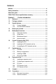
Contents Notices.......................................................................................................... vi Safety information...................................................................................... vii About this guide......................................................................................... vii P5G41T-M LX Series specifications summary.......................................... ix Chapter 1: Product introduction 1.1 Welcome!................................
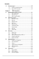
Contents 1.11 Software support......................................................................... 1-27 1.11.1 1.11.2 Chapter 2: 2.1 ASUS Update utility......................................................... 2-1 2.1.3 ASUS CrashFree BIOS.................................................... 2-3 2.2.1 BIOS menu screen........................................................... 2-5 2.2.3 Navigation keys................................................................ 2-6 2.2.5 2.2.6 2.2.7 2.2.
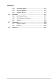
Contents 2.5.4 Anti Surge Support......................................................... 2-15 2.5.6 Hardware Monitor.......................................................... 2-16 2.5.5 2.6 Boot menu................................................................................... 2-17 2.6.1 Boot Device Priority....................................................... 2-17 2.6.3 Security.......................................................................... 2-18 2.6.2 2.7 2.
Notices Federal Communications Commission Statement This device complies with Part 15 of the FCC Rules. Operation is subject to the following two conditions: • • This device may not cause harmful interference, and This device must accept any interference received including interference that may cause undesired operation. This equipment has been tested and found to comply with the limits for a Class B digital device, pursuant to Part 15 of the FCC Rules.
Safety information Electrical safety • • • • • • To prevent electric shock hazard, disconnect the power cable from the electric outlet before relocating the system. When adding or removing devices to or from the system, ensure that the power cables for the devices are unplugged before the signal cables are connected. If possible, disconnect all power cables from the existing system before you add a device.
Conventions used in this guide To ensure that you perform certain tasks properly, take note of the following symbols used throughout this manual. DANGER/WARNING: Information to prevent injury to yourself when trying to complete a task. CAUTION: Information to prevent damage to the components when trying to complete a task. IMPORTANT: Instructions that you MUST follow to complete a task. NOTE: Tips and additional information to help you complete a task.
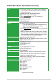
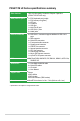
P5G41T-M LX Series specifications summary CPU LGA775 socket for Intel® Core™2 Quad / Core™2 Extreme / Core™2 Duo / Pentium® dual-core / Celeron® dual-core / Celeron® processors Compatible with Intel® 05B/05A/06 processors Supports Intel® 45nm multi-core CPU * Refer to www.asus.com for Intel® CPU support list. Chipset Northbridge: Intel® G41 Southbridge: Intel® ICH7 Front Side Bus 1333/1066/800 MHz Memory Dual channel memory architecture - 2 x 240-pin DIMM sockets support unbuffered non-ECC 1333(O.
P5G41T-M LX Series specifications summary Other features 100% All High-quality Conductive Polymer Capacitors (P5G41T-M LX PLUS only) Back panel I/O ports 1 x PS/2 keyboard port (purple) 1 x PS/2 mouse port (green) 1 x LPT port 1 x COM port 1 x VGA port 1 x LAN (RJ-45) port 4 x USB 2.0/1.1 ports 3 x Audio jacks Internal connectors 2 x USB 2.0/1.1 connectors support additional 4 USB 2.0/1.
Chapter 1 Product introduction 1.1 Welcome! Thank you for buying an ASUS® P5G41T-M LX Series motherboard! The motherboard delivers a host of new features and latest technologies, making it another standout in the long line of ASUS quality motherboards! Before you start installing the motherboard, and hardware devices on it, check the items in your package with the list below. 1.2 Package contents Check your motherboard package for the following items.
Intel® G41 Chipset The Intel® G41 Express Chipset is designed to support dual-channel DDR3 1333 (overclocking)/1066 architecture, 1333/1066/800 Front Side Bus (FSB), PCIe 1.1, and mutli-core CPUs. It especially includes Intel® Fast memory bandwidth and reduces the latency of the memory accesses. Dual channel DDR3 1333 (O.C.)/1066 support This motherboard supports DDR3 memory that features data transfer rates of 1333 (O.C.
ASUS Q-Fan ASUS Q-Fan technology intelligently adjusts the CPU fan speed according to system loading to ensure a quiet, cool, and efficient operation. ASUS Anti-Surge Protection This special design prevents expensive devices and the motherboard from damage caused by power surges from switching power supply (PSU). ASUS MyLogo2™ This feature allows you to convert your favorite photo into a 256-color boot logo for a more colorful and vivid image on your screen.
1.4 Before you proceed Take note of the following precautions before you install motherboard components or change any motherboard settings. • Unplug the power cord from the wall socket before touching any component. • Before handling components, use a grounded wrist strap or touch a safely grounded object or a metal object, such as the power supply case, to avoid damaging them due to static electricity. • Hold components by the edges to avoid touching the ICs on them.
1.5 Motherboard overview Before you install the motherboard, study the configuration of your chassis to ensure that the motherboard fits into it. Ensure that you unplug the power cord before installing or removing the motherboard. Failure to do so can cause you physical injury and damage motherboard components. 1.5.1 Placement direction 1.5.2 Screw holes When installing the motherboard, ensure that you place it into the chassis in the correct orientation.
1.5.3 Motherboard layout ASUS P5G41T-M LX Series motherboards include P5G41T-M LX V2 and P5G41T-M LX PLUS two models. The layout varies with models. The layout illustrations in this user guide are for P5G41T-M LX PLUS only. P5G41T-M LX PLUS COM1 20.1cm(7.9in) RTL 8111E ICS 9LRS954A4 9 15 1.5.4 1-6 14 13 12 11 10 Layout contents Connectors/Jumpers/Slots/LED Page Connectors/Jumpers/Slots/LED Page 1. Keyboard power (3-pin KBPWR) 1-19 9. Clear RTC RAM (3-pin CLRTC) 1-18 2.
1.6 Central Processing Unit (CPU) The motherboard comes with a surface mount LGA775 socket designed for the Intel® Core™2 Extreme / Core™2 Quad / Core™2 Duo / Pentium® dual-core / Celeron® dual-core / Celeron® processors • Unplug all power cables before installing the CPU. • Connect the CPU fan cable to the CPU_FAN connector and chassis fan cable to the CHA_FAN connector to ensure system stability.
2. Press the load lever with your thumb (A), then move it to the left (B) until it is released from the retention tab. To prevent damage to the socket pins, do not remove the PnP cap unless you are installing a CPU. Retention tab A B Load lever 3. 4. Lift the load lever in the direction of the arrow to a 135º angle. PnP cap Load plate 4B Lift the load plate with your thumb and forefinger to a 100º angle (4A), then push the PnP cap from the load plate window to remove (4B). 4A 3 5.
6. Apply some Thermal Interface Material to the exposed area of the CPU that the heatsink will be in contact with, ensuring that it is spread in an even thin layer. Some heatsinks come with pre-applied thermal paste. If so, skip this step. DO NOT eat the Thermal Interface Material. If it gets into your eyes or touches your skin, ensure that you wash it off immediately, and seek professional medical help. To prevent contaminating the paste, DO NOT spread the paste with your finger directly. 7.
1.6.2 Installing the CPU heatsink and fan The Intel® LGA775 processor requires a specially designed heatsink and fan assembly to ensure optimum thermal condition and performance. • When you buy a boxed Intel® processor, the package includes the CPU fan and heatsink assembly. If you buy a CPU separately, ensure that you use only Intel®‑certified multi‑directional heatsink and fan. • Your Intel® LGA775 heatsink and fan assembly comes in a push-pin design and requires no tool to install.
Connect the CPU fan cable to the connector on the motherboard labeled CPU_FAN. P5G41T-M LX PLUS 3. P5G41T-M LX PLUS CPU fan connector Do not forget to connect the CPU fan connector! Hardware monitoring errors can occur if you fail to plug this connector. 1.6.3 Uninstalling the CPU heatsink and fan To uninstall the CPU heatsink and fan: 1. Disconnect the CPU fan cable from the connector on the motherboard. 2. Rotate each fastener counterclockwise. 3.
4. Carefully remove the heatsink and fan assembly from the motherboard. 5. Rotate each fastener clockwise to ensure correct orientation when reinstalling. 1.7 System memory 1.7.1 Overview P5G41T-M LX PLUS The motherboard comes with two Double Data Rate 3 (DDR3) Dual Inline Memory Modules (DIMM) sockets.
1.7.2 Memory configurations You may install 512MB, 1GB, 2GB, and 4GB unbuffered non‑ECC DDR3 DIMMs into the DIMM sockets. • You may install varying memory sizes in Channel A and Channel B. The system maps the total size of the lower-sized channel for the dual-channel configuration. Any excess memory from the higher-sized channel is then mapped for single-channel operation. • Always install DIMMs with the same CAS latency.
DDR3-1333 MHz (O.C.) capability Vendor Part No. Size SS/ Chip DS Brand Chip NO. A-Data AD31333001GOU 1024MB SS A-Data AD30908C8D-151C E0906 - A-Data AD31333G001GOU 3072MB(Kit of 3) SS - - A-Data AD31333002GOU 2048MB DS A-Data AD30908C8D-151C E0903 - A-Data AD31333G002GMU 2048MB DS - Corsair CM3X1024-1333C9DHX 1024MB Corsair CM3X1024-1333C9 1024MB Corsair Timing Voltage DIMM socket support (Optional) A* - • 8-8-8-24 1.65-1.85V • - • - 8-8-8-24 1.65-1.
DDR3-1333 MHz (O.C.) capability DIMM socket support (Optional) Vendor Part No. Size SS/ Chip DS Brand Chip NO.
1.7.3 Installing a DIMM Unplug the power supply before adding or removing DIMMs or other system components. Failure to do so can cause severe damage to both the motherboard and the components. 2 1. Press the retaining clips outward to unlock a DIMM socket. 2. Align a DIMM on the socket such that the notch on the DIMM matches the DIMM slot key on the socket. DIMM notch 1 1 DIMM slot key Unlocked retaining clip A DIMM is keyed with a notch so that it fits in only one direction.
1.8 Expansion slots In the future, you may need to install expansion cards. The following sub‑sections describe the slots and the expansion cards that they support. Unplug the power cord before adding or removing expansion cards. Failure to do so may cause you physical injury and damage motherboard components. 1.8.1 Installing an expansion card To install an expansion card: 1.
1.9 Jumpers Clear RTC RAM (3-pin CLRTC) This jumper allows you to clear the Real Time Clock (RTC) RAM in CMOS. You can clear the CMOS memory of date, time, and system setup parameters by erasing the CMOS RTC RAM data. The onboard button cell battery powers the RAM data in CMOS, which include system setup information such as system passwords. P5G41T-M LX PLUS 1. P5G41T-M LX PLUS Clear RTC RAM To erase the RTC RAM: 1. Turn OFF the computer and unplug the power cord. 2.
Keyboard power (3-pin KBPWR) This jumper allows you to enable or disable the keyboard wake-up feature. When you set this jumper to pins 2–3 (+5VSB), you can wake up the computer by pressing a key on the keyboard. This feature requires an ATX power supply that can supply at least 1A on the +5VSB lead, and a corresponding setting in the BIOS. P5G41T-M LX PLUS 2.
1.10 Connectors 1.10.1 Rear panel connectors 1. PS/2 mouse port (green). This port is for a PS/2 mouse. 2. Parallel port. This 25-pin port connects a parallel printer, a scanner, or other devices. 3. LAN (RJ-45) port. This port allows Gigabit connection to a Local Area Network (LAN) through a network hub. Refer to the table below for the LAN port LED indications.
7. USB 2.0 ports 1 and 2. These two 4-pin Universal Serial Bus (USB) ports are available for connecting USB 2.0 devices. 8. USB 2.0 ports 3 and 4. These two 4-pin Universal Serial Bus (USB) ports are available for connecting USB 2.0 devices. 9. VGA port. This 15-pin port is for a VGA monitor or other VGA-compatible devices. 10. COM port. This port is for pointing devices or other serial devices. 11. PS/2 Keyboard port (purple). This port is for a PS/2 keyboard. 1.10.
2. IDE connector (40-1 pin PRI_IDE) The onboard IDE connector is for the Ultra DMA 100/66/33 signal cable. There are three connectors on each Ultra DMA 100/66/33 signal cable: blue, black, and gray. Connect the blue connector to the motherboard’s IDE connector, then select one of the following modes to configure your device.
ATX power connectors (24-pin EATXPWR, 4-pin ATX12V) These connectors are for ATX power supply plugs. The power supply plugs are designed to fit these connectors in only one orientation. Find the proper orientation and push down firmly until the connectors completely fit. P5G41T-M LX PLUS 3. P5G41T-M LX PLUS ATX power connectors • We recommend that you use an ATX 12V Specification 2.0‑compliant power supply unit (PSU) with a minimum of 400W power rating. This PSU type has 24-pin and 4-pin power plugs.
Serial ATA connectors (7-pin SATA1-4) These connectors are for the Serial ATA signal cables for Serial ATA 3Gb/s hard disk and optical disk drives. The Serial ATA 3Gb/s is backward compatible with Serial ATA 1.5Gb/s specification. The data transfer rate of the Serial ATA 3Gb/s is faster than the standard parallel ATA with 133 MB/s (Ultra DMA133). P5G41T-M LX PLUS 4. P5G41T-M LX PLUS SATA connectors Install the Windows® XP Service Pack 2 or later version before using Serial ATA.
6. CPU and chassis fan connectors (4-pin CPU_FAN, 3-pin CHA_FAN) Connect the fan cables to the fan connectors on the motherboard, ensuring that the black wire of each cable matches the ground pin of the connector. P5G41T-M LX PLUS Do not forget to connect the fan cables to the fan connectors. Insufficient air flow inside the system may damage the motherboard components.
System panel connector (10-1 pin PANEL) This connector supports several chassis-mounted functions. P5G41T-M LX PLUS 8. P5G41T-M LX PLUS System panel connector • System power LED (2-pin PLED) • Hard disk drive activity LED (2-pin +HDLED) • ATX power button/soft-off button (2-pin PWRBTN) • Reset button (2-pin RESET) 9. Speaker connector (4-pin SPEAKER) This 2-pin connector is for the system power LED. Connect the chassis power LED cable to this connector.
1.11 Software support 1.11.1 Installing an operating system This motherboard supports Windows® XP/Vista/7 Operating Systems (OS). Always install the latest OS version and corresponding updates to maximize the features of your hardware. • Motherboard settings and hardware options vary. Refer to your OS documentation for detailed information.
1-28 Chapter 1: Product introduction
Chapter 2 BIOS information 2.1 Managing and updating your BIOS Save a copy of the original motherboard BIOS file to a USB flash disk in case you need to restore the BIOS in the future. Copy the original motherboard BIOS using the ASUS Update utility. 2.1.1 ASUS Update utility The ASUS Update is a utility that allows you to manage, save, and update the motherboard BIOS in Windows® environment. • ASUS Update requires an Internet connection either through a network or an Internet Service Provider (ISP).
The ASUS Update utility is capable of updating itself through the Internet. Always update the utility to avail all its features. Updating from a BIOS file 3. a. Select Update BIOS from a file, then click Next. b. Locate the BIOS file from the Open window, then click Open. Follow the onscreen instructions to complete the updating process. 2.1.2 ASUS EZ Flash 2 The ASUS EZ Flash 2 feature allows you to update the BIOS without using an OS‑based utility.
2.1.3 ASUS CrashFree BIOS The ASUS CrashFree BIOS is an auto recovery tool that allows you to restore the BIOS file when it fails or gets corrupted during the updating process. You can restore a corrupted BIOS file using the motherboard support DVD or a removable device that contains the updated BIOS file. • Before using this utility, rename the BIOS file in the removable device into P5G41TMP.ROM. • The BIOS file in the support DVD may not be the latest version.
2.2 BIOS setup program Use the BIOS Setup program to update the BIOS or configure its parameters. The BIOS screens include navigation keys and brief online help to guide you in using the BIOS Setup program. Entering BIOS Setup at startup To enter BIOS Setup at startup: • Press during the Power-On Self Test (POST). If you do not press , POST continues with its routines. Entering BIOS Setup after POST To enter BIOS Setup after POST: • Press ++ simultaneously.
2.2.1 BIOS menu screen Menu items Main Menu bar Advanced Power System Time System Date Primary IDE Master Primary IDE Slave SATA 1 SATA 2 SATA 3 SATA 4 Configuration fields General help BIOS SETUP UTILITY Boot Tools Exit [00:31:48] [Tue 01/01/2002] :[Not :[Not :[Not :[Not :[Not :[Not Detected] Detected] Detected] Detected] Detected] Detected] Storage Configuration System Information Use [ENTER], [TAB] or [SHIFT-TAB] to select a field. Use [+] or [-] to configure system Time.
2.2.3 Navigation keys At the bottom right corner of a menu screen are the navigation keys for that particular menu. Use the navigation keys to select items in the menu and change the settings. Some of the navigation keys differ from one screen to another. 2.2.4 Menu items 2.2.5 Submenu items 2.2.6 Configuration fields 2.2.7 Pop-up window The highlighted item on the menu bar displays the specific items for that menu. For example, selecting Main shows the Main menu items.
2.3 Main menu When you enter the BIOS Setup program, the Main menu screen appears, giving you an overview of the basic system information. Refer to section 2.2.1 BIOS menu screen for information on the menu screen items and how to navigate through them.
LBA/Large Mode [Auto] Enables or disables the LBA mode. Setting to [Auto] enables the LBA mode if the device supports this mode, and if the device was not previously formatted with LBA mode disabled. Configuration options: [Disabled] [Auto] Block (Multi-sector Transfer) M [Auto] Enables or disables data multi-sectors transfers. When set to [Auto], the data transfer from and to the device occurs multiple sectors at a time if the device supports multi-sector transfer feature.
2.3.5 System Information This menu gives you an overview of the general system specifications. The BIOS automatically detects the items in this menu. BIOS Information Displays the auto-detected BIOS information. Processor Displays the auto-detected CPU specification. System Memory Displays the auto-detected system memory. 2.4 Advanced menu The Advanced menu items allow you to change the settings for the CPU and other system devices.
The following two items appear only when you set the AI Overclocking item to [MANUAL]. CPU Frequency [xxx] Displays the frequency sent by the clock generator to the system bus and PCI bus. The value of this item is auto-detected by the BIOS. Use the <+> and <-> keys to adjust the CPU frequency. You can also type the desired CPU frequency using the numeric keypad. The values range from 200 to 800. Refer to the table below for the correct Front Side Bus and CPU External Frequency settings.
Memory Voltage [Auto] Allows you to set the memory voltage. The values range from 1.20000V to 2.4600V with a 0.02000V increment. Key in the value directly or use +/- to adjust the voltage. Configuration options: [Auto] NB Voltage [Auto] Allows you to set the Northbridge voltage. The values range from 1.12500V to 1.51875V with a 0.00625V increment. Key in the value directly or use +/- to adjust the voltage. Configuration options: [Auto] VTT Voltage [Auto] Allows you to set the VTT voltage.
CPU TM Function [Enabled] Enables or disables Intel® CPU Thermal Monitor (TM) function, a CPU overheating protection function. When enabled, the CPU core frequency and voltage are reduced when the CPU overheats. Configuration options: [Disabled] [Enabled] Execute-Disable Bit Capability [Enabled] Allows you to enable or disable the No-Execution Page Protection Technology. Setting this item to [Disabled] forces the XD feature flag to always return to zero (0).
DVMT Memory [256MB] Allows you to select the DVMT memory. Configuration options: [128MB] [256MB] [Maximum DVMT] Protect Audio Video Path Mode [Lite] Allows you to select the Protected Audio-Video Path (PAVP) mode. Configuration options: [Disabled] [Lite] [Paranoid] South Bridge Configuration Audio Controller [Enabled] Allows you to set the audio controller. Configuration options: [Enabled] [Disabled] Front Panel Type [HD Audio] Allows you to select the front panel support type.
2.4.5 USB Configuration The items in this menu allows you to change the USB-related features. Select an item then press to display the configuration options. The Module Version and USB Devices Enabled items show the auto-detected values. If no USB device is detected, the item shows None. USB Functions [Enabled] Allows you to disable or enable the USB functions. Configuration options: [Disabled] [Enabled] USB 2.0 Controller [Enabled] Allows you to enable or disable USB 2.0 controller.
2.4.6 PCI PnP The PCI PnP menu items allow you to change the advanced settings for PCI/PnP devices. The menu includes setting IRQ and DMA channel resources for either PCI/PnP or legacy ISA devices, and setting the memory size block for legacy ISA devices. Take caution when changing the settings of the PCI PnP menu items. Incorrect field values can cause the system to malfunction. Plug and Play O/S [No] When set to [No], BIOS configures all the devices in the system.
2.5.5 APM Configuration Restore on AC Power Loss [Power Off] When set to [Power Off], the system goes into off state after an AC power loss. When set to [Power On], the system goes on after an AC power loss. When set to [Last State], the system goes into either off or on state, whatever the system state was before the AC power loss. Configuration options: [Power Off] [Power On] [Last State] Power On By RTC Alarm [Disabled] Allows you to enable or disable RTC to generate a wake event.
CPU Fan Profile [Optimal Mode] This item appears only when you enable the CPU Q-Fan Control feature and allows you to set the appropriate performance level of the CPU fan. Configuration options: [Optimal Mode] [Silent Mode] [Performance Mode] VCORE Voltage, 3.3V Voltage, 5V Voltage, 12V Voltage [xxxV] or [Ignored] The onboard hardware monitor automatically detects the voltage output through the onboard voltage regulators. 2.6 Boot menu The Boot menu items allow you to change the system boot options.
Full Screen Logo [Enabled] This allows you to enable or disable the full screen logo display feature. Configuration options: [Disabled] [Enabled] Set this item to [Enabled] to use the ASUS MyLogo2™ feature. AddOn ROM Display Mode [Force BIOS] Sets the display mode for option ROM. Configuration options: [Force BIOS] [Keep Current] Bootup Num-Lock [On] Allows you to select the power-on state for the NumLock.
After you have set a supervisor password, the other items appear to allow you to change other security settings. User Access Level [Full Access] This item allows you to select the access restriction to the Setup items. Configuration options: [No Access] [View Only] [Limited] [Full Access] [No Access] - prevents user access to the Setup utility. [View Only] - allows access but does not allow change to any field. [Limited] - allows changes only to selected fields, such as Date and Time.
2.7 Tools menu The Tools menu items allow you to configure options for special functions. Select an item then press to display the sub-menu. Main Advanced Power BIOS SETUP UTILITY Boot Tools Exit ASUS EZ Flash 2 AI NET 2 2.7.1 ASUS EZ Flash 2 2.7.2 AI NET 2 Press ENTER to run the utility to select and update BIOS. This utility supports 1.FAT 12/16/32 (r/w) 2.NTFS (read only) 3.CD-DISC (read only) Allows you to run ASUS EZ Flash 2. When you press , a confirmation message appears.
2.8 Exit menu The Exit menu items allow you to load the optimal or failsafe default values for the BIOS items, and save or discard your changes to the BIOS items. Main Advanced Power Exit Options Exit & Save Changes Exit & Discard Changes Discard Changes Load Setup Defaults BIOS SETUP UTILITY Boot Tools Exit Exitsystem systemsetup setup Exit aftersaving savingthe the after changes. changes. F10key keycan canbe beused used F10 forthis thisoperation. operation.
2-22 Chapter 2: BIOS information
ASUS contact information ASUSTeK COMPUTER INC. Address Telephone Fax E-mail Web site Technical Support Telephone Online support 15 Li-Te Road, Peitou, Taipei, Taiwan 11259 +886-2-2894-3447 +886-2-2890-7798 info@asus.com.tw www.asus.com.tw +86-21-38429911 support.asus.
(510)739-3777/(510)608-4555 800 Corporate Way, Fremont, CA 94539. Asus Computer International Signature : Date : Representative Person’s Name : Oct. 8, 2010 Steve Chang / President This device complies with part 15 of the FCC Rules. Operation is subject to the following two conditions: (1) This device may not cause harmful interference, and (2) this device must accept any interference received, including interference that may cause undesired operation.