Motherboard SABERTOOTH Z77
E7246 Revised Edition V2 February 2012 Copyright © 2012 ASUSTeK COMPUTER INC. All Rights Reserved. No part of this manual, including the products and software described in it, may be reproduced, transmitted, transcribed, stored in a retrieval system, or translated into any language in any form or by any means, except documentation kept by the purchaser for backup purposes, without the express written permission of ASUSTeK COMPUTER INC. (“ASUS”).
Contents Safety information....................................................................................................... vi About this guide......................................................................................................... vii SABERTOOTH Z77 specifications summary............................................................ ix Chapter 1: 1.1 1.2 1.3 Package contents....................................................................................... 1-1 Special features.
Contents 2.4 2.5 Starting up for the first time..................................................................... 2-44 Turning off the computer.......................................................................... 2-44 Chapter 3: 3.1 3.2 3.3 3.4 3.5 Knowing BIOS............................................................................................. 3-1 BIOS setup program................................................................................... 3-1 3.2.1 3.2.2 Advanced menu......
Contents 4.3.4 DIGI+ Power Control.................................................................. 4-11 4.3.5 Sensor Recorder........................................................................ 4-15 4.3.7 USB Charger+............................................................................ 4-17 4.3.6 Ai Charger+................................................................................ 4-16 4.3.8 USB 3.0 Boost...........................................................................
Safety information Electrical safety • • • • • • To prevent electrical shock hazard, disconnect the power cable from the electrical outlet before relocating the system. When adding or removing devices to or from the system, ensure that the power cables for the devices are unplugged before the signal cables are connected. If possible, disconnect all power cables from the existing system before you add a device.
About this guide This user guide contains the information you need when installing and configuring the motherboard. How this guide is organized This guide contains the following parts: • Chapter 1: Product introduction This chapter describes the features of the motherboard and the new technology it supports.
Conventions used in this guide To ensure that you perform certain tasks properly, take note of the following symbols used throughout this manual. DANGER/WARNING: Information to prevent injury to yourself when trying to complete a task. CAUTION: Information to prevent damage to the components when trying to complete a task. IMPORTANT: Instructions that you MUST follow to complete a task. NOTE: Tips and additional information to help you complete a task.
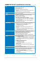
SABERTOOTH Z77 specifications summary CPU LGA 1155 socket for Intel® 3rd/2nd generation Core™ i7/i5/i3/ Pentium®/Celeron® Processors Supports 22/32nm CPU Supports Intel® Turbo Boost Technology 2.0 * The Intel® Turbo Boost Technology 2.0 support depends on the CPU types ** Refer to www.asus.com for Intel CPU support list Chipset Intel® Z77 Express Chipset Memory 4 x DIMM, Max.
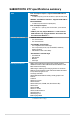
SABERTOOTH Z77 specifications summary USB Intel® Z77 Express Chipset - supports ASUS USB 3.0 Boost UASP Mode* - 4 x USB 3.0 ports (2 ports at mid-board, 2 ports at back panel) ASMedia® 1042 USB 3.0 controllers - supports ASUS USB 3.0 Boost UASP Mode - 2 x USB 3.0 ports at the back panel (blue) Intel® Z77 Express Chipset - 10 x USB 2.0/1.1 ports (6 ports at mid-board, 4 ports at back panel) * USB 3.0 ports only support Windows® 7 or later versions.
SABERTOOTH Z77 specifications summary Back Panel I/O Ports 1 x DisplayPort 1 x HDMI port 1 x Optical S/PDIF Output 1 x USB BIOS Flashback Button 2 x eSATA 6Gb/s ports 1 x LAN (RJ-45) port 4 x USB 3.0/2.0 ports (blue, 1 supports USB BIOS Flashback) 4 x USB 2.0/1.1 ports 8-channel Audio I/O ports Internal I/O Connectors 1 x USB 3.0/2.0 connector supports additional 2 USB 3.0/2.0 ports (19-pin; moss green) 3 x USB 2.0/1.1 connectors support additional 6 USB 2.0/1.
xii
Chapter 1 Chapter 1: Product introduction 1.1 Welcome! Thank you for buying an ASUS® SABERTOOTH Z77 motherboard! Chapter 1 The motherboard delivers a host of new features and latest technologies, making it another standout in the long line of ASUS quality motherboards! Before you start installing the motherboard, and hardware devices on it, check the items in your package with the list below. 1.2 Package contents Check your motherboard package for the following items.
1.3 Special features 1.3.1 Product highlights Chapter 1 LGA1155 socket for Intel® 3rd/2nd Generation Core™ i7 / Core™ i5 / Core™ i3 / Pentium® / Celeron® Processors This motherboard supports the Intel® 3rd/2nd generation Core™ i7/i5/i3/Pentium®/Celeron® processors in the LGA1155 package, with iGPU, memory, and PCI Express controllers integrated to support onboard graphics out with dedicated chipsets, 2-channel (4 DIMMs) DDR3 memory, and 16 PCI Express 3.0/2.0 lanes.
Intel® Smart Response Technology Chapter 1 SSD Speed with HDD Capacity Intel® Smart Response Technology boosts overall system performance. It uses an installed fast SSD (min 18.6GB available capacity required) as a cache for frequently accessed data. Key benefits include reduced load and wait times, and lower power consumption through the elimination of unnecessary hard drive spin.
TUF Thermal Radar Chapter 1 The TUF Thermal Radar monitors temperatures in critical parts of the motherboard in real time, automatically adjusting fan speeds to make sure the system maintains high stability. It consists of multiple sensors, giving users the ability to track each individually. Automatic calculation of ideal fan speeds based on different parameters selected manually for components has everything cooler and longer-lasting.
ESD Guards 1.3.5 Chapter 1 ESD (Electrostatic Discharge) Guards provides protection against electrostatic discharges, which can damage the motherboard’s components. The ASUS exclusive Anti-Static chip and circuit design, and the I/O shield provide four times better protection and ensure the motherboard’s lifespan.
USB Charger+ Chapter 1 With a dedicated onboard controller, quick-charge your USB devices such iProducts, smartphones, tablets, and other portable devices 50% faster, even when the PC is powered off, in sleep, or hibernation. * USB Charger+ only applies to the bottom port of USB3_12. USB BIOS Flashback With USB BIOS Flashback, simply connect a USB flash drive containing the UEFI BIOS file to the USB 3.0 port, press the BIOS Flashback button for three seconds, and the BIOS is updated automatically.
DisplayPort 1.1a Support Chapter 1 DisplayPort is a digital display interface standard that delivers up to 10.8 Gbps of bandwidth over standard cables, providing billions of colors and bidirectional communications, thus enabling the fastest refresh rates, and the highest resolution digital display through a single cable. Also, it supports HDCP copy protection for Blu-ray discs. Simply output 3D signals through the connected DisplayPort 1.
Chapter 1 1-8 Chapter 1: Product Introduction
Chapter 2 Chapter 2: Hardware information 2.1 Before you proceed Take note of the following precautions before you install motherboard components or change any motherboard settings. • Unplug the power cord from the wall socket before touching any component. • Before handling components, use a grounded wrist strap or touch a safely grounded object or a metal object, such as the power supply case, to avoid damaging them due to static electricity.
2.2 Motherboard overview 2.2.1 Motherboard layout Chapter 2 Refer to 2.2.8 Internal connectors and 2.3.11 Rear panel connection for more information about rear panel connectors and internal connectors.
Connectors/Jumpers/Slots Page 1. ATX power connectors (24-pin EATXPWR, 8-pin EATX12V) 2-24 2. CPU, chassis, and assistant fan connectors (4-pin CPU_FAN, CHA_FAN1–4, CPU_OPT, 3-pin ASST_FAN) 2-22 3. LGA1155 CPU socket 2-4 4. DDR3 DIMM slots 2-5 5. MemOK! switch 2-15 6. USB 3.0 connector (20-1 pin USB3_34) 2-20 7. Intel Z77 Serial ATA 6Gb/s connectors (7-pin SATA6G_1/2 [brown]) 2-17 8. Intel® Z77 Serial ATA 3Gb/s connectors (7-pin SATA3G_3–6 [black]) 2-18 9.
2.2.2 Central Processing Unit (CPU) The motherboard comes with a surface mount LGA1155 socket designed for the Intel® 3rd/2nd Generation Core™ i7 / Core™ i5 / Core™ i3 / Pentium / Celeron Processors. Chapter 2 Ensure that all power cables are unplugged before installing the CPU. 2-4 • The LGA1156 CPU is incompatible with the LGA1155 socket. DO NOT install a LGA1156 CPU on the LGA1155 socket.
2.2.3 System memory The motherboard comes with four Double Data Rate 3 (DDR3) Dual Inline Memory Modules (DIMM) slots. Chapter 2 A DDR3 module is notched differently from a DDR or DDR2 module. DO NOT install a DDR or DDR2 memory module to the DDR3 slot.
Memory configurations You may install 1GB, 2GB, 4GB and 8GB unbuffered and non‑ECC DDR3 DIMMs into the DIMM sockets. Chapter 2 2-6 • You may install varying memory sizes in Channel A, and Channel B. The system maps the total size of the lower-sized channel for the dual-channel configuration. Any excess memory from the higher-sized channel is then mapped for single-channel operation. • According to Intel CPU spec, DIMM voltage below 1.65V is recommended to protect the CPU.
SABERTOOTH Z77 Motherboard Qualified Vendors Lists (QVL) DDR3 1333 MHz capability Part No. Size SS/ Chip Brand DS Chip NO. Timing Voltage A-DATA AD63I1B0823EV 2GB SS A-DATA 3CCA-1509A - - A-DATA AD63I1C1624EV 4GB DS A-DATA 3CCA-1509A - - 9 - A-DATA A-DATA Apacer Apacer CORSAIR CORSAIR ELPIDA ELPIDA G.SKILL AXDU1333GC2G9(XMP) SU3U1333W8G9(XMP) 78.A1GC6.9L1 78.B1GDE.9L10C TW3X4G1333C9A CMX8GX3M2A1333C9 (XMP) EBJ20UF8BCF0-DJ-F EBJ41UF8BCF0-DJ-F F3-10600CL9D-4GBNT G.
SABERTOOTH Z77 Motherboard Qualified Vendors Lists (QVL) DDR3 1333 MHz capability (continued) Vendors Part No. Size SS/ Chip Brand DS Chip NO.
SABERTOOTH Z77 Motherboard Qualified Vendors Lists (QVL) DDR3 1600 MHz capability DIMM socket support (Optional) Vendors Part No. Size SS/ DS Chip Brand Chip NO. Timing Voltage A-DATA AM2U16BC2P1 2GB SS A-DATA 3CCD-1509A - - • • • A-DATA AX3U1600GC4G9(XMP) 4GB DS - - - 1.55~ 1.
SABERTOOTH Z77 Motherboard Qualified Vendors Lists (QVL) DDR3 1800 MHz capability Vendors Part No. Size SS/ Chip DS Brand G.SKILL F3-14400CL9D-4GBRL(XMP) 4GB (2x2GB) DS Chip Timing NO. - Voltage 9-9-9-24 1.60 DIMM socket support (Optional) 1 DIMM • 2 DIMM 4 DIMM • • SABERTOOTH Z77 Motherboard Qualified Vendors Lists (QVL) DDR3 1866 MHz capability DIMM socket support (Optional) Vendors Part No. Size SS/ Chip DS Brand Chip Timing NO.
SABERTOOTH Z77 Motherboard Qualified Vendors Lists (QVL) DDR3 2133 MHz capability DIMM socket support (Optional) Vendors Part No. Size SS/ Chip Chip Timing DS Brand NO. Voltage A-DATA AX3U2133C2G9B(XMP) 2GB SS - - 9-11-9-27 1.55~1.75 • • Apacer 78.BAGE4.AFD0C(XMP) 8GB ( 2x 4GB ) DS - - 9-9-9-24 - • CORSAIR CORSAIR CORSAIR G.SKILL G.Skill G.SKILL G.SKILL AX3U2133GC2G9B(XMP) 2GB CMT4GX3M2A2133C9(XMP) 4GB ( 2x 2GB ) CMT4GX3M2B2133C9(Ver7.
2.2.4 Expansion slots Ensure to unplug the power cord before adding or removing expansion cards. Failure to do so may cause you physical injury and damage motherboard components. Chapter 2 Slot No. Slot Description 1 PCIe 2.0 x1_1 slot 3 PCIe 2.0 x1_2 slot 2 4 5 6 PCIe 3.0 x16_1 slot (single at x16 or dual at x8/x8 mode) PCIe 3.0 x16_2 slot PCIe 2.0 x1_3 slot PCIe 2.0 x16_3 slot (max.
• • • • In single VGA card mode, use the PCIe 3.0 x16_1 slot (beige) for a PCI Express x16 graphics card to get better performance. In CrossFireX™ or SLI™ mode, use the PCIe 3.0 x16_1 and PCIe 3.0 x16_2 slots for PCI Express x16 graphics cards to get better performance. We recommend that you provide sufficient power when running CrossFireX™ or SLI™ mode. Refer to page 2-24 for details.
2.2.5 Jumper Clear RTC RAM (3-pin CLRTC) This jumper allows you to clear the Real Time Clock (RTC) RAM in CMOS. You can clear the CMOS memory of date, time, and system setup parameters by erasing the CMOS RTC RAM data. The onboard button cell battery powers the RAM data in CMOS, which include system setup information such as system passwords. Chapter 2 To erase the RTC RAM 1. Turn OFF the computer and unplug the power cord. 3. Plug the power cord and turn ON the computer. 2. 4.
2.2.6 Onboard switch The onboard switch allows you to fine-tune performance when working on a bare or opencase system. This is ideal for overclockers and gamers who continually change settings to enhance system performance. MemOK! switch Chapter 2 Installing DIMMs that are incompatible with the motherboard may cause system boot failure, and the DRAM_LED near the MemOK! switch lights continuously.
2.2.7 1. Onboard LEDs Standby Power LED The motherboard comes with a standby power LED. The green LED lights up to indicate that the system is ON, in sleep mode, or in soft‑off mode. This is a reminder that you should shut down the system and unplug the power cable before removing or plugging in any motherboard component. The illustration below shows the location of the onboard LED. Chapter 2 2.
2.2.8 1. Internal connectors Intel Z77 Serial ATA 6Gb/s connectors (7-pin SATA6G_1/2 [brown]) ® These connectors connect to Serial ATA 6Gb/s hard disk drives via Serial ATA 6Gb/s signal cables. Chapter 2 If you installed Serial ATA hard disk drives, you can create a RAID 0, 1, 5, and 10 configuration with the Intel® Rapid Storage Technology through the onboard Intel® Z77 chipset. • These connectors are set to [AHCI Mode] by default.
2. Intel® Z77 Serial ATA 3Gb/s connectors (7-pin SATA3G_3–6 [black]) These connectors connect to Serial ATA 3Gb/s hard disk drives and optical disc drives via Serial ATA 3Gb/s signal cables. If you installed Serial ATA hard disk drives, you can create a RAID 0, 1, 5, and 10 configuration with the Intel® Rapid Storage Technology through the onboard Intel® Z77 chipset. Chapter 2 2-18 • These connectors are set to [AHCI Mode] by default.
ASMedia® Serial ATA 6Gb/s connectors (7-pin SATA6G_E1/E2 [gray]) These connectors connect to Serial ATA 6Gb/s hard disk drives via Serial ATA 6Gb/s signal cables. Chapter 2 3. SABERTOOTH Z77 ASMedia SATA 6.0 Gb/s connectors • The SATA6G_E1/E2 (gray) connectors do not support ATAPI devices. • You must install Windows® XP Service Pack 3 or later versions before using Serial ATA hard disk drives. • For regular usage, the SATA6G_E1/E2 connectors are recommended for data drives.
5. USB 3.0 connector (20-1 pin USB3_34) This connector is for the additional USB 3.0 ports, and complies with the USB 3.0 specificaton that supports up to 4.8 Gbps connection speed. If the USB 3.0 front panel cable is available from your system chassis, with this USB 3.0 connector, you can have a front panel USB 3.0 solution.
USB 2.0 connectors (10-1 pin USB78, USB56, USB910) These connectors are for USB 2.0 ports. Connect the USB module cable to any of these connectors, then install the module to a slot opening at the back of the system chassis. These USB connectors comply with USB 2.0 specification that supports up to 480 Mbps connection speed. Chapter 2 6. Never connect a 1394 cable to the USB connectors. Doing so will damage the motherboard! • • • 7.
8. CPU, chassis, and assistant fan connectors (4-pin CPU_FAN; 4-pin CPU_OPT FAN; 4-pin CHA_FAN1-4; 3-pin ASST_FAN) Connect the fan cables to the fan connectors on the motherboard, ensuring that the black wire of each cable matches the ground pin of the connector. Chapter 2 Do not forget to connect the fan cables to the fan connectors. Insufficient air flow inside the system may damage the motherboard components.
Front panel audio connector (10-1 pin AAFP) This connector is for a chassis-mounted front panel audio I/O module that supports either HD Audio or legacy AC`97 audio standard. Connect one end of the front panel audio I/O module cable to this connector. • We recommend that you connect a high-definition front panel audio module to this connector to avail of the motherboard’s high-definition audio capability.
10. Chapter 2 2-24 ATX power connectors (24-pin EATXPWR; 8-pin EATX12V) These connectors are for ATX power supply plugs. The power supply plugs are designed to fit these connectors in only one orientation. Find the proper orientation and push down firmly until the connectors completely fit. • For a fully configured system, we recommend that you use a power supply unit (PSU) that complies with ATX 12 V Specification 2.0 (or later version) and provides a minimum power of 350W.
11. System panel connector (20-8 pin PANEL) • Chapter 2 This connector supports several chassis-mounted functions. System power LED (2-pin PLED) This 2-pin connector is for the system power LED. Connect the chassis power LED cable to this connector. The system power LED lights up when you turn on the system power, and blinks when the system is in sleep mode.
2.3 Building your computer system 2.3.1 Additional tools and components to build a PC system Chapter 2 1 bag of screws Philips (cross) screwdriver PC chassis Power supply unit Intel LGA 1155 CPU Intel LGA 1155 compatible CPU Fan DIMM SATA hard disk drive SATA optical disc drive (optional) Graphics card (optional) The tools and components in the table above are not included in the motherboard package.
2.3.2 CPU installation Please note the order in opening/ closing the double latch. Follow the instructions printed on the metal sealing hatch or the illustrations shown below in this manual. The plastic cap will pop up automatically once the CPU is in place and the hatch properly sealed down.
4 C A Chapter 2 B 5 2-28 Chapter 2: Hardware information
2.3.3 CPU heatsink and fan assembly installation Apply the Thermal Interface Material to the CPU heatsink and CPU before you install the heatsink and fan if necessary.
2.3.
2.3.5 Motherboard installation The diagrams in this section are for reference only. The motherboard layout may vary with models, but the installation steps remain the same.
3 Chapter 2 DO NOT overtighten the screws! Doing so can damage the motherboard.
2.3.6 Thermal Armor for ASUS SABERTOOTH Z77 The Thermal Armor for ASUS SABERTOOTH Z77 consists of a rear I/O cover fan, and a cover fan assembly, providing effective dissipation of the heat generated from the motherboard components. To ensure the most optimum heat dissipation, follow the instruction below to install the I/O cover fan to the rear I/O cover. 1. Remove the screw on the rear I/O cover, and then remove the lid to show the fan socket. 2.
4. Install the assembled fan and sponge to the rear I/O fan socket, and screw the I/O fan cover lid to close. The TUF logo must be visible along with the I/O ports. 5. Place the fan cable inside the cable slot, and connect the fan cable to the assistant fan (ASST_FAN1) connector on the motherboard Chapter 2 Keep the fan cable hidden under the thermal armor to prevent clutter. Installing the second accessory fan: 1. 2-34 Remove the fan cover lid to show the fan socket and the fan connector.
2. Place the fan into the socket, ensuring that the TUF logo is facing up, and screw to lock in place using the four bundled long screws. 3. Chapter 2 Keep the fan cable hidden under the thermal armor to prevent clutter. Connect the fan cable to the assistant fan (ASST_FAN2) connector on the motherboard. The screwdriver is not included in the package.
2.3.
2.3.
2.3.9 Front I/O Connector To install ASUS Q-Connector 1 2 IDE_LED IDE_LED+ IDE_LED- R SW POWE PWR Ground Chapter 2 Reset Ground RESET SW To install USB 2.0 Connector To install front panel audio connector AAFP USB 2.0 Remove the USB dust cover before installing the USB 2.0 connector. To install USB 3.0 Connector USB 3.
2.3.10 Rear panel connection 2 9 10 Chapter 2 8 Rear panel connectors 1. USB 2.0 ports 1, 2, 3 and 4 6. External SATA 6G 2. USB 3.0 ports 5 and 6 7 DisplayPort 3. Optical S/PDIF Out port 8. HDMI port 4. LAN (RJ-45) port* 9. USB 3.0 ports 1 and 2*** 5. USB BIOS Flashback button 10. Audio I/O ports** * and **: Refer to the tables on the next page for LAN port LED and audio port definitions. *** USB 3.0 ports 1 and 2 only support Windows 7 or later versions.
• DO NOT insert a different connector to the external SATA port. • DO NOT connect a keyboard/mouse to any USB 3.0 port when installing Windows® operating system. • Due to USB 3.0 controller limitation, USB 3.0 devices can only be used under Windows® OS environment and after the USB 3.0 driver installation. • USB 3.0 devices can only be used as data storage only. • We strongly recommend that you connect USB 3.0 devices to USB 3.0 ports for faster and better performance for your USB 3.0 devices.
2.3.11 Audio I/O connections Audio I/O ports Chapter 2 Connect to Headphone and Mic Connect to Stereo Speakers Connect to 2.
Connect to 4.1 channel Speakers Chapter 2 Connect to 5.1 channel Speakers Connect to 7.
2.3.12 USB BIOS Flashback USB BIOS Flashback allows you to update the BIOS without entering the BIOS or operating system. Just connect the USB storage device containing the BIOS file to the USB port, press the BIOS Flashback button, and the BIOS is updated automatically. 2. 3. Download the USB BIOS Flashback from the ASUS website at www.asus.com and save it to the root directory of your USB flash drive. Connect the USB flash drive to the bottom USB 3.0 port at the rear panel.
2.4 Starting up for the first time 1. After making all the connections, replace the system case cover. 3. Connect the power cord to the power connector at the back of the system chassis. 2. 4. 5. Be sure that all switches are off. Connect the power cord to a power outlet that is equipped with a surge protector. Turn on the devices in the following order: a. Monitor c. System power b. 6.
Chapter 3 Chapter 3: 3.1 Knowing BIOS BIOS setup The new ASUS UEFI BIOS is an Unified Extensible Firmware Interface that complies with UEFI architecture, offering a user-friendly interface that goes beyond traditional keyboardonly BIOS controls to enable more flexible and convenient mouse input. Users can easily navigate the new UEFI BIOS with the same smoothness as their operating system. The term “BIOS” in this user manual refers to “UEFI BIOS” unless otherwise specified.
3.2.1 EZ Mode By default, the EZ Mode screen appears when you enter the BIOS setup program. The EZ Mode provides you an overview of the basic system information, and allows you to select the display language, system performance mode and boot device priority. To access the Advanced Mode, click Exit/Advanced Mode, then select Advanced Mode. The default screen for entering the BIOS setup program can be changed. Refer to the Setup Mode item in section 3.7 Boot memu for details.
3.2.2 Advanced Mode The Advanced Mode provides advanced options for experienced end-users to configure the BIOS settings. The figure below shows an example of the Advanced Mode. Refer to the following sections for the detailed configurations. To access the EZ Mode, click Exit, then select ASUS EZ Mode.
Menu items The highlighted item on the menu bar displays the specific items for that menu. For example, selecting Main shows the Main menu items. The other items (Ai Tweaker, Advanced, Monitor, Boot, Tool, and Exit) on the menu bar have their respective menu items. Back button This button appears when entering a submenu. Press or use the USB mouse to click this button to return to the previous menu screen.
3.3 Main menu The Main menu screen appears when you enter the Advanced Mode of the BIOS Setup program. The Main menu provides you an overview of the basic system information, and allows you to set the system date, time, language, and security settings. UEFI BIOS Utility - Advanced Mode Ai Tweaker Main Exit Advanced Monitor BIOS Information BIOS Version Build Date EC Version ME Version South Bridge Stepping 0401 x64 01/12/2012 MBEC-Z77-0124 8.0.0.
Administrator Password If you have set an administrator password, we recommend that you enter the administrator password for accessing the system. Otherwise, you might be able to see or change only selected fields in the BIOS setup program. To set an administrator password: 1. Select the Administrator Password item and press . 3. Confirm the password when prompted. 2. From the Create New Password box, key in a password, then press . To change an administrator password: 1. 2. 3. 4.
3.4 Ai Tweaker menu The Ai Tweaker menu items allow you to configure overclocking-related items. Be cautious when changing the settings of the Ai Tweaker menu items. Incorrect field values can cause the system to malfunction. The configuration options for this section vary depending on the CPU and DIMM model you installed on the motherboard. UEFI BIOS Utility - Advanced Mode Main Ai Tweaker Exit Advanced Monitor Target CPU Speed : 3700MHz Boot Tool [X.M.P.
Ai Overclock Tuner [Auto] Allows you to select the CPU overclocking options to achieve the desired CPU internal frequency. Select any of these preset overclocking configuration options: [Auto] [Manual] [X.M.P.] Loads the optimal settings for the system. Allows you to individually set overclocking parameters. If you install memory modules supporting the eXtreme Memory Profile (X.M.P.) Technology, choose this item to set the profiles supported by your memory modules for optimizing the system performance.
3-Core Ratio Limit [Auto] Allows you to set the 3-Core Ratio Limit [Auto] Select to apply the CPU default Turbo Ratio setting [Manual] Select to to manually assign a 3-Core Ratio Limit value that is higher than or equal to the 4-Core Ratio Limit.
DRAM Timing Control The sub-items in this menu allow you to set the DRAM timing control features. Use the <+> and <-> keys to adjust the value. To restore the default setting, type [auto] using the keyboard and press the key. Changing the values in this menu may cause the system to become unstable! If this happens, revert to the default settings.
Scroll down to display the following items: DRAM CLK Period Auto Transmitter Slew(CHA) Auto Transmitter Slew(CHB) Auto Receiver Slew(CHA) Auto Receiver Slew(CHB) Auto MCH Duty Sense (CHA) Auto MCH Duty Sense (CHB) Auto Channel A DIMM Control Enable Both . . . Channel B DIMM Control Enable Both . . . DRAM Read Additional Swizzle Auto DRAM Write Additional Swizzle Auto →←: Select Screen ↑↓: Select Item Enter: Select +/-: Change Opt.
DRAM WRITE to READ Delay [Auto] Configuration options: [Auto] [4 DRAM Clock] – [15 DRAM Clock] DRAM CKE Minimum pulse width [Auto] Configuration options: [Auto] [4 DRAM Clock] – [15 DRAM Clock] DRAM CAS# Write to Latency [Auto] Configuration options: [Auto] [1 DRAM Clock] – [15 DRAM Clock] DRAM RTL (CHA) [Auto] Configuration options: [Auto] [1 DRAM Clock] – [15 DRAM Clock] DRAM RTL (CHB) [Auto] Configuration options: [Auto] [1 DRAM Clock] – [15 DRAM Clock] DRAM IO-L (CHA) [Auto] Configuration option
DRAM CLK Period [Auto] Allows you to set the DRAM CLK Period.
CPU Power Management UEFI BIOS Utility - Advanced Mode Main Back Ai Tweaker Exit Advanced Monitor Boot Tool Ai Tweaker\ CPU Power Management > CPU Ratio Auto Enhanced Intel SpeedStep Technology Enabled Turbo Mode Parameters Long Duration Power Limit Auto Long Duration Maintained Auto Short Duration Power Limit Auto Primary Plane Current Limit Auto Secondary Plane Current Limit Auto Allows User can manually adjust the maximum non-turbo CPU ratio.
Primary Plane Current Limit [Auto] Maximum instantaneous current allowed at any given time for CPU cores Use <+> and <-> key to adjust the value at 0.125A increment. . Secondary Plane Current Limit [Auto] Maximum instantaneous current allowed at any given time for Internal Graphics cores. Use <+> and <-> key to adjust the value at 0.125A increment.
CPU Voltage Frequency [Auto] Frequency switching affects the VRM transient response, and the thermal component. Higher frequency gets quicker transient response. Configuration options: [Auto] [Manual] DO NOT remove the thermal module when switching to Manual Mode. The thermal conditions should be monitored. VRM Spread Spectrum [Disabled] This item appears only when you set the Frequency item to [Auto] and allows you to enable the spread spectrum to enhance system stability.
iGPU Current Capability [100%] Allows you to set the iGPU Current Capability. Configuration options: [100%] [110%] [120%] [130%] [140%] DO NOT remove the thermal module while changing the DIGI+ VRM related parrameters . The thermal conditions should be monitored. Some of the following items above are adjusted by typing the desired values using the numeric keypad and press the key. You can also use the <+> and <-> keys to adjust the value.
CPU Manual Voltage [Auto] This item appears only when you set the CPU Voltage item to [Manual Mode] and allows you to set a fixed CPU voltage. The values range from 0.800V to 1.990V with a 0.005V interval. Refer to the CPU documentation before setting the CPU voltage. Setting a high voltage may damage the CPU permanently, and setting a low voltage may make the system unstable. The following items appears only when you set the Initiate iGPU items to [Enabled].
Black CPU Manual Voltage CPU Offset Voltage iGPU Offset Voltage 0.8V–1.22V DRAM Voltage VCCSA Voltage CPU PLL Voltage PCH Voltage 0.005V– 0.060V 0.005V– 0.035V 1.20000V– 1.57500V 0.80000V– 1.10000V 1.20000V– 1.88750V 0.80000V– 1.10000V Yellow 1.225V– 1.280V 0.065V– 0.120V Pink 1.285V– 1.335V 0.125V– 0.175V 0.04V–0.065V 0.07V–0.1V 1.58125V– 1.65000V 1.10625V– 1.15000V 1.89375V– 1.97500V 1.11000V– 1.15000V 1.65625V– 1.72500V 1.15625V– 1.20625V 1.98125V– 2.06875V 1.16000V– 1.20000V Red 1.340V– 1.
3.5 Advanced menu The Advanced menu items allow you to change the settings for the CPU and other system devices. Be cautious when changing the settings of the Advanced menu items. Incorrect field values can cause the system to malfunction.
3.5.1 CPU Configuration The items in this menu show the CPU-related information that the BIOS automatically detects. The items shown in this screen may be different due to the CPU you installed. UEFI BIOS Utility - Advanced Mode Ai Tweaker Main Back Exit Advanced Monitor Boot Tool Advanced\ CPU Configuration > CPU Configuration Adjust Non-Turbo Ratio Intel(R) Core(TM) i3-2130 CPU 0 @ 3.
Active Processor Cores [All] Allows you to choose the number of CPU cores to activate in each processor package. Configuration options: [All] or by CPU specification Limit CPUID Maximum [Disabled] [Enabled] [Disabled] Allows legacy operating systems to boot even without support for CPUs with extended CPUID functions. For Windows® XP OS, select this option to disable this function. [Enabled] [Disabled] Enables the No-Execution Page Protection Technology.
CPU C6 Report [Auto] Allows you to disable or enable the CPU C6 report to OS. Configuration options: [Auto] [Disabled] [Enabled] 3.5.2 PCH Configuration UEFI BIOS Utility - Advanced Mode Ai Tweaker Main Back Exit Advanced Monitor Boot Tool Advanced\ PCH Configuration > PCH Configuration High Precision Timer Enabled Enabled/Disabled the High Precision Event Timer.
Intel (R) Smart Connect Technology [Disabled] Allows you to enable or disable the Intel® Smart Connect Technology configuration. ISCT Configuration [Disabled] Configuration options: [Disabled] [Enabled] 3.5.3 SATA Configuration While entering Setup, the BIOS automatically detects the presence of SATA devices. The SATA Port items show Not Present if no SATA device is installed to the corresponding SATA port.
SATA Mode Selection [AHCI] Allows you to set the SATA configuration. [Disabled] [IDE Mode] [AHCI Mode] [RAID Mode] Disables the SATA function. Set to [IDE Mode] when you want to use the Serial ATA hard disk drives as Parallel ATA physical storage devices. Set to [AHCI Mode] when you want the SATA hard disk drives to use the AHCI (Advanced Host Controller Interface).
3.5.4 System Agent Configuration UEFI BIOS Utility - Advanced Mode Ai Tweaker Main Back Advanced Monitor Boot Tool Advanced\ System Agent Configuration > System Agent Bridge Name Memory Remap Feature IvyBridge Enabled Enable or disable memory remap above 4G. > PCH Configuration > NB PCIe Configuration Memory Remap Feature [Enabled] [Enabled] [Disabled] Allow you to enable remapping the memory above 4GB. Disables this function.
3.5.5 USB Configuration The items in this menu allow you to change the USB-related features. UEFI BIOS Utility - Advanced Mode Ai Tweaker Main Back Advanced Exit Monitor Boot Tool Advanced\ USB Configuration > USB Configuration USB Devices: 1 Keyboard, 1 Mouse, 2 Hubs Legacy USB Support Legacy USB3.0 Support Intel xHCI Mode Enabled Enables Legacy USB support. AUTO option disables legacy support if no USB devices are connected.
3.5.
PCI Express X16_3 slot (black) [X1 mode] Allows you to set the modes of the PCIe slots. [X1 mode] [X4 mode] PCIe x16_3 slot runs at X1 mode with all slots enabled. PCIe x16_3 slot runs at its highest performance support. Enabling the X4 mode disables the PCIe x1_1, PCIe x1_2 and PCIe x1_3. ASM1061 Storage Controller Front/Rear [Enable] Allows you to enable or disable the ASM1061 storage controller.
3.5.7 APM UEFI BIOS Utility - Advanced Mode Ai Tweaker Main Back Exit Advanced Monitor Boot Tool Advanced\ APM > ErP Ready Restore AC Power Loss Disabled Power Off Power On By PCIE/PCI Disabled Power On By RTC Disabled Allow BIOS yo switch off some power at S5 to get the system ready for ErP requirement. When set to Enabled, all other PME options will be switched off. ErP Ready [Disabled] This item allows user to switch off some power at S5 to get the system ready for ErP requirement.
3.5.8 Network Stack UEFI BIOS Utility - Advanced Mode Ai Tweaker Main Back Exit Advanced Monitor Boot Tool Advanced\ Network Stack > Network Stack Disable Link Enable/Disable UEFI network staack. Network Stack [Disable Link] This item allows user to disable or enable the UEFI network stack.
3.6 Monitor menu The Monitor menu displays the system temperature/power status, and allows you to change the fan settings.
Scroll down to display the following items: ASST 1 Fan Speed Low Limit 600 RPM ASST 1 Fan Profile Standard ASST 2 Q-Fan Control Enabled ASST 2 Fan Speed Low Limit 600 RPM ASST 2 Fan Profile Standard Fan Overtime 1 minute Anti Surge Support Enabled Enter: Select +/-: Change Opt. F1: General Help F2: Previous Values F5: Optimized Defaults F10: Save ESC: Exit F12: Print Screen Version 2.10.1208. Copyright (C) 2012 American Megatrends, Inc.
The following four items appear only when you set CPU Fan Profile to [Manual]. CPU Upper Temperature [70] Use the <+> and <-> keys to adjust the upper limit of the CPU temperature. The values range from 20ºC to 75ºC. CPU Fan Max. Duty Cycle(%) [100] Use the <+> and <-> keys to adjust the maximum CPU fan duty cycle. The values range from 0% to 100%. The minimum value can not lower than the setting of Min duty cycle. When the CPU temperature reaches 75 degree, fan will run up to full speed.
Chassis 1/2/3/4 Lower Temperature [40] Displays the lower limit of the chassis temperature. Chassis 1/2/3/4 Fan Min. Duty Cycle(%) [60] Use the <+> and <-> keys to adjust the minimum chassis fan duty cycle. The values range from 60% to 100%. When the chassis temperature is under 40ºC, the chassis fan will operate at the minimum duty cycle. ASST 1/2 Q-Fan Control [Enabled] [Disabled] [Enabled] Disables the Assistant Q-Fan control feature. Enables the Assistant Q-Fan control feature.
Allow Fan Stop [Disable] Allows your assistant fans to run at 0% cycle when the motherboard’s temperature drops to a certain degree. Configuration options: [Disable] [Enable] Fan Overtime [1 minute] Allows you to set the turbo fan’s working time to extend for good heat dissipation, and lowers the temperature after system shutdown.
3.7 Boot menu The Boot menu items allow you to change the system boot options. UEFI BIOS Utility - Advanced Mode Ai Tweaker Main Exit Advanced Monitor Bootup NumLock State On Full Screen Logo Enabled Wait for ‘F1’ If Error Option ROM Messages Boot Tool Select the keyboard NumLock state Enabled Force BIOS Setup Mode EZ Mode UEFI/Legacy Boot Enable bot... PCI ROM Priority Legacy ROM Boot Option Priorities →←: Select Screen ↑↓: Select Item Enter: Select +/-: Change Opt.
Setup Mode [EZ Mode] [Advanced Mode] Sets Advanced Mode as the default screen for entering the BIOS setup program. [EZ Mode] Sets EZ Mode as the default screen for entering the BIOS setup program. UEFI/Legacy Boot [Enable both UEFI and Legacy] [Enable both UEFI and Legacy] [Disable UEFI] Enables both UEFI and Legacy boot. Enables the Legacy boot, and disables the UEFI boot. [Disable Legacy Enables the UEFI booth, and disables the Legacy boot.
3.8 Tool menu The Tool menu items allow you to configure options for special functions. Select an item then press to display the submenu. UEFI BIOS Utility - Advanced Mode Ai Tweaker Main Exit Advanced Monitor Boot Tool Be used to update BIOS > ASUS EZ Flash 2 Utility > ASUS O.C. Profile > ASUS SPD Information 3.8.1 ASUS EZ Flash 2 Utility Allows you to run ASUS EZ Flash 2 Utility. When you press , a confirmation message appears.
Label Allows you to input the label of setup profile. Save to Profile Allows you to save the current BIOS settings to the BIOS Flash, and create a profile. Key in a profile number from one to eight, press , and select Yes. You can also do this by or keying the <+> or <->, press and select Yes. Load from Profile Allows you to load the previous BIOS settings saved in the BIOS Flash. Key in a profile number from one to eight, press , and select Yes.
3.9 Exit menu The Exit menu items allow you to load the optimal default values for the BIOS items, and save or discard your changes to the BIOS items. You can access the EZ Mode from the Exit menu. Exit Load Optimized Defaults Save Changes & Reset Discard Changes & Exit ASUS EZ Mode Launch UEFI Shell from filesystem device Load Optimized Defaults This option allows you to load the default values for each of the parameters on the Setup menus.
3.10 Updating BIOS The ASUS website publishes the latest BIOS versions to provide enhancements on system stability, compatibility, or performance. However, BIOS updating is potentially risky. If there is no problem using the current version of BIOS, DO NOT manually update the BIOS. Inappropriate BIOS updating may result in the system’s failure to boot. Carefully follow the instructions of this chapter to update your BIOS if necessary. Visit the ASUS website (www.asus.
Updating the BIOS through the Internet To update the BIOS through the Internet: 1. From the ASUS Update screen, select Update BIOS from Internet, and then click Next. 2. Select the ASUS FTP site nearest you to avoid network traffic. If you want to enable the BIOS downgradable function and auto BIOS backup function, check the checkboxs before the two items on the screen. Select the BIOS version that you want to download. Click Next. 4.
Updating the BIOS through a BIOS file To update the BIOS through a BIOS file: Chapter 3 1. From the ASUS Update screen, select Update BIOS from file, and then click Next. 2. Locate the BIOS file from the Open window, click Open, and click Next. 3. You can decide whether to change the BIOS boot logo. Click Yes if you want to change the boot logo or No to continue. 4. 3-44 Follow the onscreen instructions to complete the update process. • The screenshots in this section are for reference only.
3.10.2 ASUS EZ Flash 2 utility The ASUS EZ Flash 2 feature allows you to update the BIOS without having to use a bootable floppy disk or an OS‑based utility. Before you start using this utility, download the latest BIOS from the ASUS website at www.asus.com. To update the BIOS using EZ Flash 2: 1. 2. Insert the USB flash disk that contains the latest BIOS file to the USB port. Enter the Advanced Mode of the BIOS setup program.
• This function can support devices such as a USB flash disk with FAT 32/16 format and single partition only. • DO NOT shut down or reset the system while updating the BIOS to prevent system boot failure! Ensure to load the BIOS default settings to ensure system compatibility and stability. Select the Load Optimized Defaults item under the Exit menu. See section 3.9 Exit Menu for details. 3.10.
3.10.4 ASUS BIOS Updater The ASUS BIOS Updater allows you to update BIOS in DOS environment. This utility also allows you to copy the current BIOS file that you can use as a backup when the BIOS fails or gets corrupted during the updating process. The succeeding utility screens are for reference only. The actual utility screen displays may not be same as shown. Before updating BIOS 1. 2. 3. Prepare the motherboard support DVD and a USB flash drive in FAT32/16 format and single partition.
Backing up the current BIOS To backup the current BIOS file using the BIOS Updater Ensure that the USB flash drive is not write-protected and has enough free space to save the file. 1. At the FreeDOS prompt, type bupdater /o[filename] and press . D:\>bupdater /oOLDBIOS1.rom Filename Extension The [filename] is any user-assigned filename with no more than eight alphanumeric characters for the filename and three alphanumeric characters for the extension. 2.
Updating the BIOS file To update the BIOS file using BIOS Updater 1. At the FreeDOS prompt, type bupdater /pc /g and press . D:\>bupdater /pc /g 2. The BIOS Updater screen appears as below. ASUSTek BIOS Updater for DOS V1.18 [2012/01/12] Current ROM BOARD: SABERTOOTH Z77 VER: 0262 DATE: 01/12/2012 Update ROM BOARD: Unknown VER: Unknown DATE: Unknown PATH: A:\ SABERZ77.
Chapter 3 3-50 Chapter 3: BIOS setup
Chapter 4 Chapter 4: 4.1 Software support Installing an operating system This motherboard supports Windows® XP/ 64-bit XP/ 7 / 64-bit 7 operating systems (OS). Always install the latest OS version and corresponding updates to maximize the features of your hardware. 4.2 • Motherboard settings and hardware options vary. Use the setup procedures presented in this chapter for reference only. Refer to your OS documentation for detailed information.
4.2.2 Obtaining the software manuals The software manuals are included in the support DVD. Follow the instructions below to get the necessary software manuals. The software manual files are in Portable Document Format (PDF). Install the Adobe® Acrobat® Reader from the Utilities menu before opening the files. 1. Click on the Manual tab. Click on ASUS Motherboard Utility Guide from the manual list on the left. 2. The Manual folder of the support DVD appears.
4.3 Software information Most of the applications in the support DVD have wizards that will conveniently guide you through the installation. View the online help or readme file that came with the software application for more information. 4.3.1 AI Suite II AI Suite II is an all-in-one interface that integrates several ASUS utilities and allows users to launch and operate these utilities simultaneously. Installing AI Suite II To install AI Suite II on your computer 1. 2. 3.
4.3.2 ASUS TUF Thermal Radar The TUF Thermal Radar monitors temperatures in critical parts of the motherboard in real time, automatically adjusting fan speeds to make sure the system maintains high stability without overheating. It consists of multiple sensors for various components on the motherboard, giving user the ability to monitor each one individually.
Configuring system fan settings The TUF Thermal Radar provides easy-to-use fan profiles for adjusting the CPU fan, assistant fan (I/O cover fan and cover fan), and the chassis fan speeds according to different ambient temperatures caused by different climate conditions in different geographic regions and your PC’s system loading. Thermal Radar also provides fully-customizable fan speed control, offering the most flexible controls of fan speed to achieve a quiet and cool environment.
Configuring user-customizable fan settings You can customize the fan speed to meet different computing and environment needs. To fast customize the fan speed 1. 2. 3. Select User in the Profile Name dropdown list. Drag the control points on the fan speed curve to set the fan speed percentage. Click Apply.
4. If you are not sure how to choose the proper components to monitor and the percentage to adjust, click Auto and have Thermal Radar do the recommended settings for you. Click Apply for the setting to take effect. Configuring Fan-Off settings When this function is selected, the fans automatically turn off when the temperature drops to a certain level and run when the system’s temperature rises. To enable or disable the assistant fans: 1. 2. 3. Click and select the fan from the Fan Name drop-down list.
Configuring Fan Overtime settings Allows you to customize the fan’s working time to dissipate the remaining heat after shutting down or in standby mode. To fast customize the fan overtime: 1. 2. 3. Click . Drag the scroll bar on the Fan Overtime screen. Click Apply. Click Undo to cancel the fan overtime settings made. Click and drag to set time for fan overtime Click to save and apply the changes made Click to undo the changes made • Maximum fan overtime is 10 minutes.
4.3.3 TurboV EVO ASUS TurboV EVO introduces TurboV that allows you to manually adjust the CPU frequency and related voltage values. After installing AI Suite II from the motherboard support DVD, launch TurboV EVO by clicking Tool > TurboV EVO on the AI Suite II main menu bar. Refer to the software manual in the support DVD or visit the ASUS website at www.asus.com for detailed software configuration.
Using Advanced Mode Click on the Advanced Mode tab to adjust the advanced voltage settings. Advanced mode Target values Voltage Adjustment bars Undoes all changes without applying Applies all changes immediately Current values Click to restore all start-up settings CPU Ratio Allows you to manually adjust the CPU ratio. 1. 2. 3. 4. Click the CPU Ratio tab. Click ON to activate the CPU Ratio function. The system automatically reboots for the changes to take effect.
4.3.4 DIGI+ Power Control DIGI+ PowerControl allows you to adjust VRM voltage and frequency modulation to enhance reliability and stability. It also provides the highest power efficiency, generating less heat to longer component lifespan and minimize power loss. After installing AI Suite II from the motherboard support DVD, launch DIGI+ Power Control by clicking Tool > DIGI+ Power Control on the AI Suite II main menu bar. Select CPU Power or DRAM Power to adjust the power control settings.
7 Application aids 8 9 Apply all changes immediately Click to proceed to previous page Function no. Undo all changes without applying Function description 7 CPU Power Thermal Control A higher temperature brings a wider CPU power thermal range and extends the overclocking performance to enlarge O.C potential. 8 CPU Power Response Control Provides a faster and precise power response rate for your CPU. Apply a higher value for extreme overclocking.
DRAM Power 1 Application aids 2 3 4 Apply all changes immediately Undo all changes without applying Function no. Function description 1 DRAM Current Capability A higher value brings a wider total power range and extends the overclocking frequency range simultaneously. 2 DRAM Voltage Frequency Allows you to adjust the DRAM switching frequency for system stability or to increase OC Range.
Smart DIGI+ 1 2 Applies the default settings Function no. Function description 1 35W Allows you to limit the wattage to 35W for power saving. 2 45W Allows you to limit the wattage to 45W for power saving. Setting a specific wattage decreases the total power delivery to the CPU, and affects the system’s performance under a heavy system load. • • The actual performance boost may vary depending on your CPU and DRAM specification. Do not remove the thermal module.
4.3.5 Sensor Recorder Sensor Recorder monitors the changes in the system voltage, temperature, and fan speed on a timeline. The History Record function allows you to designate specific time spans on record to keep track of the three system statuses for certain purposes. Launching Sensor Recorder After installing AI Suite II from the motherboard support DVD, launch Sensor Recorder by clicking Tool > Sensor Recorder on the AI Suite II main menu bar.
4.3.6 Ai Charger+ This utility allows you to fast-charge your portable BC 1.1* mobile devices on your computer’s USB port three times faster than the standard USB devices**. • *Check your USB device manufacturer if it fully supports the BC 1.1 function. • **The actual charging speed may vvary with your USB device’s conditions. To launch Ai Charger+, click, Tool > Ai Charger+ on the AI Suite II main menu bar.
4.3.7 USB Charger+ This utility allows you to fast-charge your portable USB devices even if your PC is off, in Sleep Mode, or Hibernate Mode. Launching the USB Charger+ To launch this utility, open the AI Suite II, then click Tool > USB Charger+.
Setting up the charging function When a portable device is connected to the USB port of the PC, the USB Charger+ automatically detects the kind of your device. Charging the device Click to fast-charge your device. Indicates that the portable device is in charging mode Click to fast-charge your connected device. Click to rescan the connected device. Clicking the stops the charging of your connected device, and rescans for other detected devices. Click the to re-enable the fast-charging.
4.3.8 USB 3.0 Boost The ASUS exclusive USB 3.0 Boost provides speed boost for USB 3.0 devices and the up-to-date support of USB Attached SCSI Protocol (UASP). With USB 3.0 Boost, you can accelerate the transfer speed of your USB 3.0 devices with ease. Launching USB 3.0 Boost After installing AI Suite II from the motherboard support DVD, launch USB 3.0 Boost by clicking Tool > USB 3.0 Boost on the AI Suite II main menu bar. Configuring USB 3.0 Boost 1. 2. 3. Connect a USB 3.0 device to the USB 3.
4.3.9 Network iControl ASUS Network iControl, a one-stop setup network control center that gives you the EZ Start, Quick Connection, and EZ Profile functions, makes it easier for you to manage your network bandwidth. It also allows you to automatically connect to a PPPoE network for a more convenient online experience. To launch Network iControl, click Tool > Network iControl from AI Suite II main menu bar. • Ensure to install the LAN drivers before using this function.
Using Quick Connection Configuring the PPPoE connection settings Before enabling the Network iControl’s Quick Connection functions, you must configure the PPPoE connection settings To configure the PPPoE settings: 1. in the taskbar, and select Open Network and Sharing Center. Right-click 2. Right-click the PPPoE Connection, and select Properties. 3. Click the Options tab, and deselect Prompt for name and password, certificate, etc. Click OK to complete the auto PPPoE connection settings.
Configuring the Quick Connection To configure the auto-PPPoE connection: 1. Click the Quick Connection tab. 2. Tick Automatically connect online anytime option, then select the connection name in the Connection Name dropdown box. 3. Click Apply to enable PPPoE automatic network connection. You can also enable the No Delay TCP function to help improve the network performance.
Using EZ Profile To use the EZ Profile: EZ Profile allows you to load, edit, and save your own network program priority profile. 1. Click the EZ Profile tab. The programs are shown in the network program column. 2. Select the network program, and click 3. Click to save the changes and/or rename your profile. 4. Click , , or to set the program priority as High, Normal, or Low.
4.3.10 ASUS Update ASUS Update lays out the options for updating BIOS on your system. Update BIOS utility on your system or simply save the utility for later use just by following the directions on this convenient updating feature. Launching ASUS Update After installing AI Suite II from the motherboard support DVD, launch ASUS Update by clicking Update> ASUS Update on the AI Suite II main menu bar. Using ASUS Update Select the way you would like to do with the BIOS utility.
4.3.11 MyLogo2 This MyLogo utility lets you customize the boot logo. The boot logo is the image that appears on screen during the Power‑On‑Self-Tests (POST). Personalize your computer from the very beginning! Launching ASUS Update After installing AI Suite II from the motherboard support DVD, launch MyLogo by clicking Update> MyLogo on the AI Suite II main menu bar. Using MyLogo Select the way you would like to do update your boot logo. Then click Next and follow the given instructions.
2. Click on Auto Tune to adjust image size compatibility or adjust the resolution bar. 4. Click on Flash to start updating the image to the boot logo. 3. 5. You can click on Booting Preview to preview the boot image. Then click Next. Click on Yes to reboot or you can also see the new logo next time you restart your computer. Change the boot logo of a downloaded BIOS file and update (or do not update) this BIOS to the motherboard 1. 2. 3.
4.3.12 Audio configurations The Realtek audio CODEC provides 8-channel audio capability to deliver the ultimate audio experience on your computer. The software provides Jack-Detection function, S/PDIF Out support, and interrupt capability. The CODEC also includes the Realtek® proprietary UAJ® (Universal Audio Jack) technology for all audio ports, eliminating cable connection errors and giving users plug and play convenience.
4.4 RAID configurations The motherboard comes with the Intel® Z77 chipset controller that allows you to configure Serial ATA hard disk drives as RAID sets. The motherboard supports the following RAID configurations: • Intel® Rapid Storage Technology with RAID 0, RAID 1, RAID 10 and RAID 5 support. 4.4.1 • You must install Windows® XP Service Pack 3 or later versions before using Serial ATA hard disk drives.
4.4.2 Installing Serial ATA hard disks The motherboard supports Serial ATA hard disk drives. For optimal performance, install identical drives of the same model and capacity when creating a disk array. To install the SATA hard disks for a RAID configuration: 1. Install the SATA hard disks into the drive bays. 3. Connect a SATA power cable to the power connector on each drive. 2. Connect the SATA signal cables. 4.4.
The navigation keys at the bottom of the screen allow you to move through the menus and select the menu options. The RAID BIOS setup screens shown in this section are for reference only and may not exactly match the items on your screen. The utility supports maximum four hard disk drives for RAID configuration. Creating a RAID set To create a RAID set: 1. From the utility main menu, select 1. Create RAID Volume and press .
5. 6. Use the up/down arrow key to select a drive, and then press to select. A small triangle marks the selected drive. Press after completing your selection. Use the up/down arrow key to select the stripe size for the RAID array (for RAID 0, 10 and 5 only),and then press . The available stripe size values range from 4KB to 128KB.
Deleting a RAID set Take caution when deleting a RAID set. You will lose all data on the hard disk drives when you delete a RAID set. To delete a RAID set: 1. From the utility main menu, select 2. Delete RAID Volume and press . The following screen appears: Intel(R) Rapid Storage Technology - Option ROM - v10.0.0.1032 Copyright(C) 2003-10 Intel Corporation. All Rights Reserved. [ DELETE VOLUME MENU ] Name Volume0 Level RAID0(Stripe) Drives 2 Capacity 298.
4.4.5 Intel® 2012 Desktop responsiveness technologies This section details the overview of the installation and configuration procedures of the Intel® 2012 Desktop responsiveness technologies.
SSD Capacity Requirements Intel® storage combinations SSD Partition Capacity Requirements System DRAM 2GB 4GB 8GB Intel® Rapid Start 2GB 4GB 8GB Intel® Smart Response 20GB 20GB 20GB Intel® Smart Response and Intel® Rapid Start Separate 20GB and 2GB partition (SSD size > 22GB) Separate 20GB and 4GB partition (SSD size > 24GB) Separate 20GB and 8GB partition (SSD size > 28GB) Intel® Smart Response, Intel® Rapid Start, and Intel® Smart Connect Separate 20GB and 2GB partition (SSD size > 22GB
Intel® Smart Response Technology Intel® Smart Response Technology boosts overall system performance. It uses an installed SSD with at least 20GB size as a cache for frequently-accessed operations. It speeds up hard drive and main memory interaction, reduces load and wait time, maximizes storage usage, and saves power via the reduction on unnecessary hard drive spin. Before applying Intel® Smart Response Technology, setting the SATA Mode BIOS item to [RAID mode] in BIOS setup is necessary.
3. Select Disable Acceleration to disable this function, and select Change Mode to • > 20GB) To enable Intel® Smart Response Technology, you need at least one SSD (= and an HDD, and only one SSD can be assigned for caching. • If you want to restore the OS, go to BIOS Option ROM > Acceleration Options and remove the Disks/Volume Acceleration to disable Intel® Smart Response Technology. Refer to Chapter 4, section Installing Serial ATA hard disk for the entry of BIOS Option ROM.
3. Right click the New Volume that you want to shrink from, and select Shrink Volume. 4. If your SSD is not initialized and not formatted: a. Right-click the disk that you want to partition, and select Initialize. b. Right-click the unallocated volume, select New Simple Volume, and follow the remaining steps. If your SSD is smaller than 64GB, and is set to Full disk capacity caching option for Intel® Smart Response, you cannot see any volume in the Disk Management.
6. To launch the disk partitioning tool, click Start > Programs > Accessories > Command Prompt tool. 7. Type diskpart and press Enter. 8. In the diskpart prompt, type list disk after DISKPART, and press Enter. Select the disk with the unallocated volume by typing select disk x (x = disk number), and press Enter . • • The value “x” refers to a disk number where you created the unallocated partition. Refer to step 5 for details about the unallocated disk space in the SSD. 9.
12. Type set id=84 override, press Enter, and wait for the “shrinking process” until the Disk Management utility identifies a new partition called Hibernation Partition. The Hibernation Partition does not appear when you choose “GPT (GUID Partition Table store type”. Ensure the “Unallocated” disappears from the volume, and a new partition is identified. 13. Reboot the system after creating the partition.
2. Tick On in the Status field to enable the function, and click Save. Select and click to enable or disable the function Click to enable or disable battery saving mode. This function only applies to notebooks. Click to enable or disable the timer. When enabled, move the scroll bar to the desired time. When the system is idle for more than the time period you set, the system automatically goes into the Intel® Rapid Start mode. Default time is 10 minutes.
5. Type list partition, press Enter, and select the partition where the Intel® Rapid Start Technology is installed by typing select partition x (x = number), and press Enter. The value “x” refers to a disk number where you want to delete the store partition. Type delete partition override, and press Enter. The diskpart utility deletes the selected partition. 7. In the desktop, click Start, right-click Computer, and click Manage. 8.
10. Click Next after selecting the default selected disk. 11. Extend volume setup is completed. Click Finish to recover the Intel® Rapid Start Technology partition. 12. 13. Reboot the system after deleting the partition. Go to Start > Control Panel > Programs > Programs and Features > to remove the Intel® Rapid Start Manager for the complete deletion of Intel® Rapid Start Technology.
5. Select all and click Next for Custom Setup. 6. Click Install to proceed the installation. 7. Click Yes to restart your system, and for the newly installed Intel® Smart Connect Technology to take effect. Using the Intel® Smart Connect Technology • • 1. 2. Before the system goes to sleep mode, ensure to keep your applications on the desktop, and enter the applications, passwords. Ensure that the internet is in connection when enabling the Intel® Smart Connect Technology.
3. To disable the updating function, click Disable Updating. Clicking this button automatically disables the configuration in the Advanced tab. To reset to defaults, click Reset All to Defaults. 4. In the Advanced tab, set up the schedule during low power usage time period for power saving. This setting only applies to the assigned time period. 5. In the Help tab, click About to view the feature’s version. Click Topics to learn more about the Intel® Smart Connect Technology and its configuration.
4.5 Creating a RAID driver disk A floppy disk with the RAID driver is required when installing a Windows® operating system on a hard disk drive that is included in a RAID set. 4.5.1 • The motherboard does not provide a floppy drive connector. You have to use a USB floppy disk drive when creating a SATA RAID driver disk. • Windows® XP may not recognize the USB floppy disk drive due to Windows® XP limitation. To work around this OS limitation, refer to section 4.5.4 Using a USB floppy disk drive.
4.5.3 Installing the RAID driver during Windows® OS installation To install the RAID driver in Windows® XP: 1. 2. 3. 4. During the OS installation, the system prompts you to press the F6 key to install thirdparty SCSI or RAID driver. Press , and then insert the floppy disk with RAID driver into the USB floppy disk drive. When prompted to select the SCSI adapter to install, select the RAID driver for the corresponding OS version.
4.5.4 Using a USB floppy disk drive Due to OS limitation, Windows® XP may not recognize the USB floppy disk drive when you install the RAID driver from a floppy disk during the OS installation. To solve this issue, add the USB floppy disk drive’s Vendor ID (VID) and Product ID (PID) to the floppy disk containing the RAID driver. Refer to the steps below: 1. Using another computer, plug the USB floppy disk drive, and insert the floppy disk containing the RAID driver. 2.
7. Use Notepad to open the file. 8. Find the [HardwareIds.scsi.iaAHCI_DesktopWorkstationServer] and [HardwareIds.scsi.iaStor_DesktopWorkstationServer] sections in the txtsetup.oem file. 9. Type the following line to the bottom of the two sections: id = “USB\VID_xxxx&PID_xxxx”, “usbstor” [HardwareIds.scsi.iaAHCI_DesktopWorkstationServer] id= “PCI\VEN_8086&DEV_1C02&CC_0106”,”iaStor” id= “USB\VID_03EE&PID_6901”, “usbstor” [HardwareIds.scsi.
Chapter 5 Chapter 5: Multiple GPU technology support 5.1 AMD® CrossFireX™ technology The motherboard supports the AMD CrossFireX™ technology that allows you to install multi-graphics processing units (GPU) graphics cards. Follow the installation procedures in this section. ® 5.1.1 • • • Requirements In Dual CrossFireX mode, you should have two identical CrossFireX-ready graphics cards or one CrossFireX-ready dual-GPU graphics card that are AMD® certified.
5.1.3 Installing two CrossFireX™ graphics cards Chapter 5 The following pictures are for reference only. The graphics cards and the motherboard layout may vary with models, but the installation steps remain the same. 1. 2. 3. 4. Prepare two CrossFireX-ready graphics cards. Insert the two graphics card into the PCIEX16 slots.
5.1.4 Installing the device drivers Refer to the documentation that came with your graphics card package to install the device drivers. 5.1.5 Enabling the AMD® CrossFireX™ Chapter 5 Ensure that your PCI Express graphics card driver supports the AMD® CrossFireX™ technology. Download the latest driver from the AMD website (www.amd.com). technology After installing your graphics cards and the device drivers, enable the CrossFireX™ feature through the AMD Catalyst™ Control Center in Windows environment.
5.2 NVIDIA® SLI™ technology The motherboard supports the NVIDIA® SLI™ (Scalable Link Interface) technology that allows you to install multi-graphics processing units (GPU) graphics cards. Follow the installation procedures in this section. Chapter 5 5.2.1 • • • Requirements In SLI mode, you should have two identical SLI-ready graphics cards that are NVIDIA® certified. Ensure that your graphics card driver supports the NVIDIA SLI technology. Download the latest driver from the NVIDIA website (www.
5. 6. Align and firmly insert the SLI bridge connector to the goldfingers on each graphics card. Ensure that the connector is firmly in place. Connect two independent auxiliary power sources from the power supply to the two graphics cards separately. Chapter 5 4. Connect a VGA or a DVI cable to the graphics card. SLI bridge Goldfingers 5.2.3 Installing the device drivers Refer to the documentation that came with your graphics card package to install the device drivers.
If you cannot see the NVIDIA Control Panel item in step (A), select Personalize. B2. From the Personalization window, select Display Settings. B3. From the Display Settings dialog box, click Advanced Settings. Chapter 5 B1.
Select the NVIDIA GeForce tab, and then click Start the NVIDIA Control Panel. B5. The NVIDIA Control Panel window appears. Chapter 5 B4. Enabling SLI settings From the NVIDIA Control Panel window, select Set SLI Configuration. Click Enable SLI and set the display for viewing SLI rendered content. When done, click Apply.
5.3 LucidLogix Virtu MVP Chapter 5 LucidLogix Virtu MVP allows your computer’s VGA output and discrete graphic cards to perform better, respond faster and process media files smoother within a low power environment. Its GPU virtualization assigns tasks to the best available graphic source while the newly-designed Virtual Vsync gives you a smoother gaming experience. 5.3.1 • LucidLogix Virtu MVP supports Windows 7® operating systems.
5.3.2 Setting up your display Chapter 5 LucidLogix Virtu MVP solution comes with two distinct modes that allows you to enjoy better graphics either from your built-in video output (i-Mode) or from a discrete graphics card (d-Mode). i-Mode To use LucidLogix Virtu MVP in i-Mode, the display must be connected to the onboard video output. Ensure to set the Primary Display to iGPU in BIOS to activate i-Mode support.
5.3.3 Configuring LucidLogix Virtu MVP Chapter 5 Launch the Virtu MVP Control Panel to allow you to configure the main features, adjust the performance settings and select applications for graphical virtualization. To open the control panel, right-click LucidLogix Virtu MVP icon in the notification area and select Open Virtu MVP Control Panel. LucidLogix Virtu MVP is automatically activated when your system is powered on.
Performance Chapter 5 Allows you to turn ON/OFF the Hyperformance® or Virtual Vsync function.
Applications Allows you to select applications for graphic virtualization. Chapter 5 Click to select a program to run by discrete card, iGPU, or Hyperformance® Click to add, edit, or remove programs See the descriptions of these columns below: • D column allows you to run applications with the discrete graphic card. Select D to enable 3D graphical performance for that application. • I column allows to run applications with iGPU. Select I for applications with media extensive performance.
Appendices Notices Appendices Federal Communications Commission Statement • • Appendices This device complies with Part 15 of the FCC Rules. Operation is subject to the following two conditions: This device may not cause harmful interference. This device must accept any interference received including interference that may cause undesired operation. This equipment has been tested and found to comply with the limits for a Class B digital device, pursuant to Part 15 of the FCC Rules.
Canadian Department of Communications Statement Appendices This digital apparatus does not exceed the Class B limits for radio noise emissions from digital apparatus set out in the Radio Interference Regulations of the Canadian Department of Communications. This class B digital apparatus complies with Canadian ICES-003.
ASUS contact information ASUSTeK COMPUTER INC. Technical Support Telephone Online support 15 Li-Te Road, Peitou, Taipei, Taiwan 11259 +886-2-2894-3447 +886-2-2890-7798 info@asus.com.tw www.asus.com.tw Appendices Address Telephone Fax E-mail Web site +86-21-38429911 support.asus.
(510)739-3777/(510)608-4555 800 Corporate Way, Fremont, CA 94539. Asus Computer International Signature : Date : Representative Person’s Name : Jan. 20, 2012 Steve Chang / President This device complies with part 15 of the FCC Rules. Operation is subject to the following two conditions: (1) This device may not cause harmful interference, and (2) this device must accept any interference received, including interference that may cause undesired operation.