E17358 First Edition / December 2020 Maintenance and Service Guide
COPYRIGHT INFORMATION No part of this manual, including the products and software described in it, may be reproduced, transmitted, transcribed, stored in a retrieval system, or translated into any language in any form or by any means, except documentation kept by the purchaser for backup purposes, without the express written permission of ASUSTeK COMPUTER INC. (“ASUS”).
Table of Contents Disclaimer......................................................................................................................4 Safety precautions......................................................................................................4 Major components.....................................................................................................6 Installation tools.........................................................................................................
Disclaimer ASUS is not responsible for direct, indirect, intentional or unintentional damages resulting from improper installation and operation. Safety precautions • Keep liquids or moisture away from your Notebook PC before installing or removing any components. • Ensure to place your Notebook PC on a stable surface before installing or removing any components. • Detach the clip or flap before removing the signal cables to prevent damage.
• Before handling components, use a grounded wrist strap or touch a safely grounded object to avoid damaging them due to static electricity. • Keep liquids or moisture away from your Notebook PC to avoid short circuits. • Hold components by the edges to avoid touching the ICs. • Ensure to properly install all the components before connecting the AC power. • Do not use power adapters or batteries from other devices to reduce the risk of injury to persons due to fire or explosion.
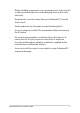
Major components VGA connector USB 2.0 connector USB 3.2 Gen 2 Type-C® connector HDMI connector USB 3.2 Gen 1 connector USB 3.
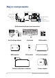
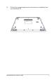
Installation tools Screwdriver Plastic blade Tweezers Removing the compartment cover NOTE: The appearance of your Notebook PC’s bottom view may vary per model. A. Remove the screw(s) from the Notebook PC’s compartment cover.
B. Prepare the plastic blade. C. Use the plastic blade to pry open the indicated area of the compartment cover as shown in the illustration below. IMPORTANT! Avoid sliding the plastic blade along the side of your Notebook PC to prevent damage.
D. Pull out the compartment cover and remove it completely from your Notebook PC.
Installing a RAM module Upgrade the memory capacity of your Notebook PC by installing a RAM (Random Access Memory) module in the memory module compartment. The following steps show you how to install a RAM module into your Notebook PC: WARNING! Disconnect all the connected peripherals, any telephone or telecommunication lines and power connector (such as external power supply, battery pack, etc.) before removing the compartment cover.
A. Remove the compartment cover. NOTE: For more details, refer to the Removing the compartment cover section in this manual. B. Disconnect the cable from the battery connector.
C. Prepare the plastic blade. D. Use the plastic blade to pry open the shielding case. E. Remove the shielding case.
F. Align and insert the RAM module into the RAM module slot. G. Push down the RAM module until it clicks in place.
H. 14 Reinstall the shielding case.
Installing an M.2 card Refer to the following steps when installing a compatible M.2 card in your Notebook PC: IMPORTANT! Purchase your M.2 card from authorized retailers of this Notebook PC to ensure maximum compatibility and reliability. WARNING! Disconnect all the connected peripherals, any telephone or telecommunication lines and power connector (such as external power supply, battery pack, etc.) before removing the compartment cover. NOTE: • The appearance of your Notebook PC’s bottom view and M.
A. Remove the compartment cover. NOTE: For more details, refer to the Removing the compartment cover section in this manual. B. 16 Disconnect the cable from the battery connector.
C. Prepare the plastic blade. D. Use the plastic blade to pry open the shielding case. E. Remove the shielding case.
F. 18 Align and place the thermal pad as shown in the illustration below.
G. Align and insert the M.2 card into the module slot. H. Secure the M.2 card in place using the bundled screw(s).
I. 20 Reinstall the shielding case.
Installing the Hard Disk Drive Refer to the following steps if you need to install a new HDD (Hard Disk Drive) to your Notebook PC: IMPORTANT! Purchase an HDD from authorized retailers of this Notebook PC to ensure maximum compatibility and reliability. WARNING! Disconnect all the connected peripherals, any telephone or telecommunication lines and power connector (such as external power supply, battery pack, etc.) before removing the compartment cover.
A. Remove the compartment cover. NOTE: For more details, refer to the Removing the compartment cover section in this manual. B. 22 Disconnect the cable from the battery connector.
C. Prepare the HDD. D. Connect the FPC connector to the HDD. E. Align and wrap the bundled mylar around the HDD as shown in the illustration below.
F. Align and place the rubber sleeve on the HDD as shown in the illustration below. G. Place the HDD in the compartment.
H. Connect the cable to the motherboard, then push down the flap on the connector to secure the cable.
Replacing the LCD module IMPORTANT! Do not bend the LCD panel in any ways to avoid risk of LCD panel leakage. NOTE: The illustrations are for reference only . A. Remove the compartment cover. NOTE: For more details, refer to the Removing the compartment cover section in this manual. B. 26 Disconnect the cable from the battery connector.
C. Use the tweezers to remove the hinge cap. ASUS ExpertBook D. Remove the two screw(s).
E. 28 Use the plastic blade to pry loose the bezel as shown in the illustration below.
F. Gently hold the edge to lift up the bezel around the display panel. IMPORTANT! Avoid pressing on the display panel to prevent damage.
G. 30 Remove the bezel.
H. Locate the tip of the adhesive strips near the top area of the display panel. I. Carefully pull the adhesive strips out one part at a time as shown in the illustration below. IMPORTANT! Avoid pulling the adhesive strips with excessive force or the adhesive strips might break.
J. 32 Flip forward the display panel as shown in the illustration below.
K. Locate the display panel connector. L. Lift the tape and then disconnect the cable from the display panel connector.
M. 34 Remove the display panel.
N. Prepare the new adhesive strips. O. Remove the release liner underneath the adhesive strips. P. Align and apply the adhesive strips as shown in the illustration below.
Q. 36 Remove the release liner above the adhesive strips.
R. Prepare the new display panel. S. Place the new display panel in the orientation as shown in the illustration below.
T. Reconnect the cable to the display panel connector. U. Reattach the tape to secure the cable in place.
V. Flip the display panel back in place. W. Align and place down the display panel until it is seated firmly in place as shown in the illustration below.
X. 40 Align and gently reattach the bezel around the display panel.
Y. Secure the two screw(s) that you removed earlier.
Wiring and connection diagrams Top View 42 Maintenance and Service Guide
Bottom View 1. Display connector 9. 2. Power supply connector 10. Keyboard connector 3. LAN connector 11. Battery connector 4. USB 3.2 Gen 2 Type-C® connector 12. HDD connector 5. HDMI connector 13. Fan connector 6. USB 3.2 Gen 1 Type-A connector 14. Headphone/Headset/Microphone jack 7. SSD connector 15. USB 2.0 Type-A connector 8. DDR4 DIMM sockets 16.
Maintenance and Service Guide