• P8H61-M LX3 R2.0 • P8H61-M LX3 PLUS R2.0 Motherboard P8H61-M LX3 R2.
E7998 Second Edition December 2012 Copyright © 2012 ASUSTeK COMPUTER INC. All Rights Reserved. No part of this manual, including the products and software described in it, may be reproduced, transmitted, transcribed, stored in a retrieval system, or translated into any language in any form or by any means, except documentation kept by the purchaser for backup purposes, without the express written permission of ASUSTeK COMPUTER INC. (“ASUS”).
Contents Safety information....................................................................................... vi About this guide.......................................................................................... vi P8H61-M LX3 R2.0 Series specifications summary................................ viii Chapter 1: Product introduction 1.1 Welcome!....................................................................................... 1-1 1.3 Special features......................................
Contents 1.11 Software support......................................................................... 1-27 1.11.1 1.11.2 Chapter 2: 2.1 2.3 ASUS Update utility......................................................... 2-1 2.1.3 ASUS CrashFree BIOS 3 utility....................................... 2-3 2.1.4 ASUS BIOS Updater........................................................ 2-4 Main menu................................................................................... 2-10 2.3.
Contents 2.6.3 CPU Voltage, 3.3V Voltage, 5V Voltage, 12V Voltage... 2-20 2.6.5 Chassis Q-Fan Control [Enabled].................................. 2-21 2.6.4 2.7 2.6.6 2.7.1 Bootup NumLock State [On].......................................... 2-23 2.7.3 Wait for ‘F1’ If Error [Enabled]........................................ 2-23 2.7.4 2.7.5 2.7.6 2.7.7 2.7.8 2.7.9 Full Screen Logo [Enabled]............................................ 2-23 Option ROM Messages [Force BIOS]...........................
Safety information Electrical safety • • • • • • To prevent electric shock hazard, disconnect the power cable from the electric outlet before relocating the system. When adding or removing devices to or from the system, ensure that the power cables for the devices are unplugged before the signal cables are connected. If possible, disconnect all power cables from the existing system before you add a device.
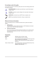
Conventions used in this guide To ensure that you perform certain tasks properly, take note of the following symbols used throughout this manual. DANGER/WARNING: Information to prevent injury to yourself when trying to complete a task. CAUTION: Information to prevent damage to the components when trying to complete a task. IMPORTANT: Instructions that you MUST follow to complete a task. NOTE: Tips and additional information to help you complete a task.
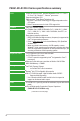
P8H61-M LX3 R2.0 Series specifications summary CPU Chipset Memory Expansion slots Graphics Storage LAN Audio USB Other features LGA1155 socket for Intel® 3rd/2nd Generation Core™ i7 / Core™ i5 / Core™ i3 / Pentium® / Celeron® processors Supports Intel 22nm CPU Supports Intel® Turbo Boost Technology 2.0 * The Intel® Turbo Boost Technology 2.0 support depends on the CPU types. ** Refer to www.asus.com for Intel® CPU support list. Intel® H61 Express Chipset 2 x DIMMs, max. 16GB, DDR3 2200 (O.C.
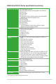
P8H61-M LX3 R2.0 Series specifications summary ASUS unique features ASUS Anti-Surge Protection ASUS UEFI BIOS featuring friendly graphics user interface ASUS AI Suite II ASUS Fan Xpert ASUS Q-Fan 2 ASUS Network iControl* featuring instant network bandwidth domination for top network program in use ASUS AI Charger ASUS WebStorage ASUS CrashFree BIOS 3 ASUS EZ Flash 2 ASUS MyLogo 2™ * The ASUS Network iControl feature does not support Windows® XP/Vista operating systems.
Chapter 1 Product introduction 1.1 Welcome! Thank you for buying an ASUS® P8H61-M LX3 R2.0 Series motherboard! The motherboard delivers a host of new features and latest technologies, making it another standout in the long line of ASUS quality motherboards! Before you start installing the motherboard, and hardware devices on it, check the items in your package with the list below. 1.2 Package contents Check your motherboard package for the following items. Motherboard ASUS P8H61-M LX3 R2.
Intel® H61 Express Chipset The Intel® H61 Express Chipset is the latest single-chipset design to support the new 1155 socket Intel® 3rd/2nd Generation Core™ i7 / Core™ i5 / Core™ i3 / Pentium® / Celeron® processors. It provides improved performance by utilizing serial point-to-point links, which allows increased bandwidth and stability. Dual-Channel DDR3 2200 (O.C.) / 2133 (O.C.) / 2000 (O.C.) / 1866 (O.C.
1.3.2 Innovative ASUS features ASUS UEFI BIOS Flexible and Easy BIOS Interface ASUS UEFI BIOS offers the first mouse-controlled graphical BIOS designed with selectable modes, providing a user-friendly interface that goes beyond the traditional keyboard-only controls. It also natively supports fully-utilized hard drives larger than 2.2TB in 64-bit operating systems. ASUS exclusive interface EZ Mode displays frequently-accessed info.
AI Suite II With its fast user-friendly interface, ASUS AI Suite II consolidates all the exclusive ASUS features into one simple to use software package. It allows you to supervise overclocking, energy management, fan speed control, and voltage and sensor readings. This all-in-one software offers diverse and ease to use functions, with no need to switch back and forth between different utilities.
1.4 Before you proceed Take note of the following precautions before you install motherboard components or change any motherboard settings. • Unplug the power cord from the wall socket before touching any component. • Before handling components, use a grounded wrist strap or touch a safely grounded object or a metal object, such as the power supply case, to avoid damaging them due to static electricity. • Hold components by the edges to avoid touching the ICs on them.
1.5 Motherboard overview Before you install the motherboard, study the configuration of your chassis to ensure that the motherboard fits into it. Ensure that you unplug the power cord before installing or removing the motherboard. Failure to do so can cause you physical injury and damage motherboard components. 1.5.1 Placement direction 1.5.2 Screw holes When installing the motherboard, ensure that you place it into the chassis in the correct orientation.
1.5.3 Motherboard layout 1 2 3 1 4 17.3cm(6.8in) KBMS CPU_FAN CHA_FAN EATXPWR LAN1_USB12 22.6cm(8.9in) USB34 DDR3 DIMM_B1 (64bit, 240-pin module) LGA1155 DDR3 DIMM_A1 (64bit, 240-pin module) VGA ATX12V Lithium Cell CMOS Power AUDIO 2 PCIEX1_2 VIA VT1708S SB_PWR USB56 USB78 USB910 CLRTC AAFP 64Mb BIOS SATA3G_2 F_PANEL SPEAKER 11 1.5.4 SATA3G_3 Intel® H61 Super I/O SATA3G_4 PCIEX1_1 SATA3G_1 PCIEX16 P8H61-M LX3 R2.
1.6 Central Processing Unit (CPU) The motherboard comes with a surface mount LGA1155 socket designed for the Intel® 3rd / 2nd Generation Core™ i7 / i5 / i3 / Pentium® / Celeron® processors. Unplug all power cables before installing the CPU. • Upon purchase of the motherboard, ensure that the PnP cap is on the socket and the socket contacts are not bent. Contact your retailer immediately if the PnP cap is missing, or if you see any damage to the PnP cap/socket contacts/motherboard components.
3. Lift the load lever in the direction of the arrow until the load plate is completely lifted. Load plate 4. Remove the PnP cap from the CPU socket by lifting the tab only. PnP cap 5. Position the CPU over the socket, ensuring that the gold triangle is on the bottom‑left corner of the socket, and then fit the socket alignment keys into the CPU notches. The CPU fits in only one correct orientation.
6. Apply some Thermal Interface Material to the exposed area of the CPU that the heatsink will be in contact with, ensuring that it is spread in an even thin layer. Some heatsinks come with preapplied thermal paste. If so, skip this step. The Thermal Interface Material is toxic and inedible. DO NOT eat it. If it gets into your eyes or touches your skin, wash it off immediately, and seek professional medical help. 7.
1.6.2 Installing the CPU heatsink and fan The Intel® LGA1155 processor requires a specially designed heatsink and fan assembly to ensure optimum thermal condition and performance. • When you buy a boxed Intel® processor, the package includes the CPU fan and heatsink assembly. If you buy a CPU separately, ensure that you use only Intel®‑certified multi‑directional heatsink and fan. • Your Intel® LGA1155 heatsink and fan assembly comes in a push-pin design and requires no tool to install.
3. Connect the CPU fan cable to the connector on the motherboard labeled CPU_FAN. CPU FAN PWM CPU FAN IN CPU FAN PWR GND CPU_FAN P8H61-M LX3 R2.0 Series P8H61-M LX3 R2.0 Series CPU fan connector Do not forget to connect the CPU fan connector! Hardware monitoring errors can occur if you fail to plug this connector. 1.6.3 Uninstalling the CPU heatsink and fan To uninstall the CPU heatsink and fan: 1. Disconnect the CPU fan cable from the connector on the motherboard. 2.
4. Carefully remove the heatsink and fan assembly from the motherboard. 5. Rotate each fastener clockwise to ensure correct orientation when reinstalling. 1.7 System memory 1.7.1 Overview DIMM_A1 DIMM_B1 The motherboard comes with two Double Data Rate 3 (DDR3) Dual Inline Memory Modules (DIMM) sockets. A DDR3 module has the same physical dimensions as a DDR2 DIMM but is notched differently to prevent installation on a DDR2 DIMM socket.
1.7.2 Memory configurations You may install 1GB, 2GB, 4GB and 8GB unbuffered non‑ECC DDR3 DIMMs into the DIMM sockets. • You may install varying memory sizes in Channel A and Channel B. The system maps the total size of the lower-sized channel for the dual-channel configuration. Any excess memory from the higher-sized channel is then mapped for single-channel operation. • Always install DIMMs with the same CAS latency.
DDR3-2250 (O.C.) MHz capability Vendors Part No. Size SS/DS KINGSTON KHX2250C9D3T1K2/4GX(XMP) 4GB(2 x 2GB) DS Chip Brand Chip NO. - DIMM socket Voltage support (optional) 1DIMM 2DIMMs 1.65V • • Timing - - DDR3-2200 (O.C.) MHz capability Vendors Part No. Size SS/DS G.
DDR3-1866 (O.C.) MHz capability Vendors Part No. Size SS/DS CORSAIR CORSAIR CORSAIR G.SKILL G.SKILL G.SKILL G.SKILL KINGSTON KINGSTON KINGSTON KINGSTON CMT4GX3M2A1866C9(XMP) CMT6GX3MA1866C9(XMP) CMZ8GX3M2A1866C9(XMP) F3-14900CL9Q-16GBZL(XMP1.3) F3-14900CL10Q2-64GBZLD(XMP1.
DDR3-1066 MHz capability Vendors Part No. Crucial ELPIDA ELPIDA KINGSTON KINGSTON Micron CT12864BA1067.8FF EBJ10UE8EDF0-AE-F EBJ21UE8EDF0-AE-F KVR1066D3N7/2G KVR1066D3N7/4G MT16JTF25664AZ-1G1F1 Size 1GB 1GB 2GB 2GB 4GB 2GB SS/DS Chip Brand SS SS DS DS DS DS Micron ELPIDA ELPIDA ELPIDA Hynix Micron Chip NO. 9GF22D9KPT J1108EDSE-DJ-F J1108EDSE-DJ-F J1108BDSE-DJ-F H5TQ2G83AFR 9HF22D9KPT Timing Voltage 7 7 7 7 1.35V(low voltage) 1.35V(low voltage) 1.5V 1.
1.7.3 Installing a DIMM Unplug the power supply before adding or removing DIMMs or other system components. Failure to do so can cause severe damage to both the motherboard and the components. 2 1. Press the retaining clips outward to unlock a DIMM socket. 2. Align a DIMM on the socket such that the notch on the DIMM matches the DIMM slot key on the socket. DIMM notch 1 1 DIMM slot key Unlocked retaining clip A DIMM is keyed with a notch so that it fits in only one direction.
1.8 Expansion slots In the future, you may need to install expansion cards. The following sub‑sections describe the slots and the expansion cards that they support. Unplug the power cord before adding or removing expansion cards. Failure to do so may cause you physical injury and damage motherboard components. 1.8.1 Installing an expansion card To install an expansion card: 1.
1.9 Jumpers Clear RTC RAM (3-pin CLRTC) This jumper allows you to clear the Real Time Clock (RTC) RAM in CMOS. You can clear the CMOS memory of date, time, and system setup parameters by erasing the CMOS RTC RAM data. The onboard button cell battery powers the RAM data in CMOS, which include system setup information such as system passwords. CLRTC 1 2 2 Normal (Default) Clear RTC 3 P8H61-M LX3 R2.0 Series P8H61-M LX3 R2.0 Series Clear RTC RAM To erase the RTC RAM: 1.
1.10 Connectors 1.10.1 Rear panel connectors 1 2 9 8 7 3 4 6 5 1. PS/2 Mouse port. This port connects to a PS/2 mouse. 2. LAN (RJ-45) port. This port allows Gigabit connection to a Local Area Network (LAN) through a network hub. Refer to the table below for the LAN port LED indications.
6. USB 2.0 ports 1 and 2. These two 4-pin Universal Serial Bus (USB) ports are for USB 2.0/1.1 devices. 7. USB 2.0 ports 3 and 4. These two 4-pin Universal Serial Bus (USB) ports are for USB 2.0/1.1 devices. 8. D-Sub port. This 15-pin port connects to a VGA monitor or other VGA-compatible devices. 9. PS/2 Keyboard port. This port connects to a PS/2 keyboard. 1.10.
2. ATX power connectors (24-pin EATXPWR, 4-pin ATX12V) These connectors are for ATX power supply plugs. The power supply plugs are designed to fit these connectors in only one orientation. Find the proper orientation and push down firmly until the connectors completely fit. GND GND +12V DC +12V DC ATX12V P8H61-M LX3 R2.
3. Intel® H61 Serial ATA 3.0Gb/s connectors (7-pin SATA3G_1~4) These connectors connect to Serial ATA 3.0 Gb/s hard disk drives and optical drives via Serial ATA 3.0 Gb/s signal cables. SATA3G_1 GND RSATA_RXP1 RSATA_RXN1 GND RSATA_TXN1 RSATA_TXP1 GND SATA3G_3 P8H61-M LX3 R2.0 Series GND RSATA_RXP3 RSATA_RXN3 GND RSATA_TXN3 RSATA_TXP3 GND SATA3G_2 GND RSATA_TXP2 RSATA_TXN2 GND RSATA_RXN2 RSATA_RXP2 GND SATA3G_4 GND RSATA_TXP4 RSATA_TXN4 GND RSATA_RXN4 RSATA_RXP4 GND P8H61-M LX3 R2.
4. CPU and chassis fan connectors (4-pin CPU_FAN, 4-pin CHA_FAN) Connect the fan cables to the fan connectors on the motherboard, ensuring that the black wire of each cable matches the ground pin of the connector. CPU FAN PWM CPU FAN IN CPU FAN PWR GND CPU_FAN CHA_FAN P8H61-M LX3 R2.0 Series CHA FAN PWM CHA FAN IN CHA FAN PWR GND P8H61-M LX3 R2.0 Series Fan connectors Do not forget to connect the fan cables to the fan connectors.
6. System panel connector (10-1 pin F_PANEL) This connector supports several chassis-mounted functions. F_PANEL PWRBTN PLED+ PLEDPWR GND PLED HD_LED+ HD_LEDGround Reset PIN 1 P8H61-M LX3 R2.0 Series +HDLED RESET P8H61-M LX3 R2.0 Series System panel connector • • • • 7. System power LED (2-pin PLED) This 2-pin connector is for the system power LED. Connect the chassis power LED cable to this connector.
1.11 Software support 1.11.1 Installing an operating system This motherboard supports Windows® XP / Vista / 7 Operating Systems (OS). Always install the latest OS version and corresponding updates to maximize the features of your hardware. • Motherboard settings and hardware options vary. Refer to your OS documentation for detailed information.
1-28 ASUS P8H61-M LX3 R2.
Chapter 2 BIOS information 2.1 Managing and updating your BIOS Save a copy of the original motherboard BIOS file to a USB flash disk in case you need to restore the BIOS in the future. Copy the original motherboard BIOS using the ASUS Update utility. 2.1.1 ASUS Update utility The ASUS Update is a utility that allows you to manage, save, and update the motherboard BIOS in Windows® environment. • ASUS Update requires an Internet connection either through a network or an Internet Service Provider (ISP).
The ASUS Update utility is capable of updating itself through the Internet. Always update the utility to avail all its features. Updating from a BIOS file Select Update BIOS from file, then click Next. a. 3. Locate the BIOS file from the Open window, then click Open. b. Follow the onscreen instructions to complete the updating process. 2.1.2 ASUS EZ Flash 2 The ASUS EZ Flash 2 feature allows you to update the BIOS without using an OS‑based utility.
3. 4. 5. 6. Press to switch to the Drive field. Press the Up/Down arrow keys to find the USB flash disk that contains the latest BIOS, and then press . Press to switch to the Folder Info field. Press the Up/Down arrow keys to find the BIOS file, and then press to perform the BIOS update process. Reboot the system when the update process is done. • This function supports USB flash disks with FAT 32/16 format and single partition only.
2.1.4 ASUS BIOS Updater The ASUS BIOS Updater allows you to update BIOS in DOS environment. This utility also allows you to copy the current BIOS file that you can use as a backup when the BIOS fails or gets corrupted during the updating process. The succeeding utility screens are for reference only. The actual utility screen displays may not be same as shown. Before updating BIOS 1. 2. Prepare the motherboard support DVD and a USB flash drive in FAT32/16 format and single partition.
Updating the BIOS file To update the BIOS file using BIOS Updater 1. At the FreeDOS prompt, type bupdater /pc /g and press . D:\>bupdater /pc /g 2. The BIOS Updater screen appears as below. ASUSTek BIOS Updater for DOS V1.18 Current ROM BOARD: P8H61-M LX3 R2.0 VER: 0303 DATE: 04/25/2012 Update ROM BOARD: Unknown VER: Unknown DATE: Unknown PATH: A:\ H61MLX3R.CAP A: Note [Enter] Select or Load [Up/Down/Home/End] Move 3.
2.2 BIOS setup program Use the BIOS Setup program to update the BIOS or configure its parameters. The BIOS screens include navigation keys and brief online help to guide you in using the BIOS Setup program. Entering BIOS Setup at startup To enter BIOS Setup at startup: • Press during the Power-On Self Test (POST). If you do not press , POST continues with its routines. Entering BIOS Setup after POST To enter BIOS Setup after POST: • Press ++ simultaneously.
EZ Mode By default, the EZ Mode screen appears when you enter the BIOS setup program. The EZ Mode provides you an overview of the basic system information, and allows you to select the display language, system performance mode and boot device priority. To access the Advanced Mode, click Exit/Advanced Mode or press Esc, then select Advanced Mode or press F7 hot key for the advanced BIOS settings. The default screen for entering the BIOS setup program can be changed.
Advanced Mode The Advanced Mode provides advanced options for experienced end-users to configure the BIOS settings. The figure below shows an example of the Advanced Mode. Refer to the following sections for the detailed configurations. To access the EZ Mode, click Exit, then select ASUS EZ Mode.
Menu items The highlighted item on the menu bar displays the specific items for that menu. For example, selecting Main shows the Main menu items. The other items (Ai Tweaker, Advanced, Monitor, Boot, Tool, and Exit) on the menu bar have their respective menu items. Back button This button appears when entering a submenu. Press or use the USB mouse to click this button to return to the previous menu screen.
2.3 Main menu The Main menu screen appears when you enter the Advanced Mode of the BIOS Setup program. The Main menu provides you an overview of the basic system information, and allows you to set the system date, time, language, and security settings. 2.3.1 System Language [English] 2.3.2 System Date [Day xx/xx/xxxx] 2.3.3 System Time [xx:xx:xx] 2.3.4 Security Allows you to choose the BIOS language version from the options.
Administrator Password If you have set an administrator password, we recommend that you enter the administrator password for accessing the system. Otherwise, you might be able to see or change only selected fields in the BIOS setup program. To set an administrator password: 1. Select the Administrator Password item and press . 3. Confirm the password when prompted. 2. From the Create New Password box, key in a password, then press . To change an administrator password: 1. 2. 3. 4.
2.4 Ai Tweaker menu The Ai Tweaker menu items allow you to configure overclocking-related items. Be cautious when changing the settings of the Ai Tweaker menu items. Incorrect field values can cause the system to malfunction. The configuration options for this section vary depending on the CPU and DIMM model you installed on the motherboard. UEFI BIOS Utility - Advanced Mode Ai Tweaker Main Exit Advanced Monitor Boot Tool [X.M.P.
2.4.4 OC Tuner 2.4.5 DRAM Timing Control OC Tuner automatically overclocks the frequency and voltage of CPU and DRAM for enhancing the system performance. Press and select OK to start automatic overclocking. The sub-items in this menu allow you to set the DRAM timing control features. Use the <+> and <-> keys to adjust the value. To restore the default setting, type [auto] using the keyboard and press .
2.5 Advanced menu The Advanced menu items allow you to change the settings for the CPU and other system devices. Be cautious when changing the settings of the Advanced menu items. Incorrect field values can cause the system to malfunction. 2.5.1 CPU Configuration The items in this menu show the CPU-related information that the BIOS automatically detects. The items shown in submenu may be different due to the CPU you installed.
Execute Disable Bit [Enabled] [Enabled] [Disabled] Enables the No-Execution Page Protection Technology. Forces the XD feature flag to always return to zero (0). Intel Virtualization Technology [Disabled] [Enabled] Allows a hardware platform to run multiple operating systems separately and simultaneously, enabling one system to virtually function as several systems. [Disabled] Disables this function.
2.5.2 PCH Configuration High Precision Timer [Enabled] Allows you to enable or disable the High Precision Event Timer. Configuration options: [Enabled] [Disabled] Intel(R) Rapid Start Technology Intel(R) Rapid Start Technology [Disabled] Allows you to enable or disable the Intel(R) Rapid Start Technology. Configuration options: [Enabled] [Disabled] The following three items appear only when you set the Intel(R) Rapid Start Technology to [Enabled].
SATA Mode Selection [IDE] Allows you to set the SATA configuration. [Disabled] Disables the SATA function. [IDE] Set to [IDE] when you want to use the Serial ATA hard disk drives as Parallel ATA physical storage devices. [AHCI] Set to [AHCI] when you want the SATA hard disk drives to use the AHCI (Advanced Host Controller Interface).
2.5.5 USB Configuration The items in this menu allow you to change the USB-related features. The USB Devices item shows the auto-detected values. If no USB device is detected, the item shows None. Legacy USB Support [Enabled] [Enabled] [Disabled] [Auto] Enables the support for USB devices on legacy operating systems (OS). The USB devices can be used only for the BIOS setup program. Allows the system to detect the presence of USB devices at startup. If detected, the USB controller legacy mode is enabled.
2.5.7 APM Restore AC Power Loss [Power Off] [Power On] [Power Off] [Last State] The system goes into on state after an AC power loss. The system goes into off state after an AC power loss. The system goes into either off or on state, whatever the system state was before the AC power loss. Power On By PS/2 Keyboard [Disabled] [Disabled] [Space Bar] [Ctrl-Esc] [Power Key] Disables the Power On by a PS/2 keyboard. Sets the Space Bar on the PS/2 keyboard to turn on the system.
2.6 Monitor menu The Monitor menu displays the system temperature/power status, and allows you to change the fan settings. Scroll down to display the following items: 2.6.1 CPU Temperature / MB Temperature ������������� [xxxºC/xxxºF] The onboard hardware monitor automatically detects and displays the CPU and motherboard temperatures. Select Ignore if you do not wish to display the detected temperatures. 2.6.
2.6.4 [Disabled] [Enabled] CPU Q-Fan Control [Enabled] Disables the CPU Q-Fan control feature. Enables the CPU Q-Fan control feature. CPU Fan Speed Low Limit [600 RPM] This item appears only when you enable the CPU Q-Fan Control feature and allows you to disable or set the CPU fan warning speed.
Chassis Fan Profile [Standard] This item appears only when you enable the Chassis Q-Fan Control feature and allows you to set the appropriate performance level of the chassis fan. [Standard] Sets to [Standard] to make the chassis fan automatically adjust depending on the chassis temperature. [Silent] Sets to [Silent] to minimize the fan speed for quiet chassis fan operation. [Turbo] Sets to [Turbo] to achieve maximum chassis fan speed.
2.7 Boot menu The Boot menu items allow you to change the system boot options. UEFI BIOS Utility - Advanced Mode Ai Tweaker Main Exit Advanced Bootup NumLock State Full Screen Logo Wait For ‘F1’ If Error Option ROM Messages Monitor On Boot Tool Select the keyboard NumLock state Enabled Enabled Force BIOS Setup Mode EZ Mode UEFI/Legacy Boot Enabled both...
2.7.4 [Force BIOS] Option ROM Messages [Force BIOS] [Keep Current] The third-party ROM messages will be forced to display during the boot sequence. The third-party ROM messages will be displayed only if the third-party manufacturer had set the add-on device to do so. 2.7.5 Setup Mode [EZ Mode] 2.7.6 UEFI/Legacy Boot [Enabled both UEFI and Legacy] 2.7.7 PCI ROM Priority [Legacy ROM] 2.7.
2.8 Tools menu The Tools menu items allow you to configure options for special functions. Select an item then press to display the submenu. EFI BIOS Utility - Advanced Mode Ai Tweaker Main Advanced Exit Monitor Boot Tool Be used to update BIOS > ASUS EZ Flash 2 Utility > ASUS SPD Information > ASUS O.C. Profile 2.8.1 ASUS EZ Flash 2 Utility Allows you to run ASUS EZ Flash 2. Press [Enter] to launch the ASUS EZ Flash 2 screen. For more details, refer to section 2.1.2 ASUS EZ Flash 2. 2.
2.9 Exit menu The Exit menu items allow you to load the optimal default values for the BIOS items, and save or discard your changes to the BIOS items. You can access the EZ Mode from the Exit menu. Exit Load Optimized Defaults Save Changes & Reset Discard Changes & Exit ASUS EZ Mode Launch EFI Shell from filesystem device Load Optimized Defaults This option allows you to load the default values for each of the parameters on the Setup menus.
Appendices Notices Federal Communications Commission Statement This device complies with Part 15 of the FCC Rules. Operation is subject to the following two conditions: • This device may not cause harmful interference. • This device must accept any interference received including interference that may cause undesired operation. This equipment has been tested and found to comply with the limits for a Class B digital device, pursuant to Part 15 of the FCC Rules.
Canadian Department of Communications Statement This digital apparatus does not exceed the Class B limits for radio noise emissions from digital apparatus set out in the Radio Interference Regulations of the Canadian Department of Communications. This class B digital apparatus complies with Canadian ICES-003.
ASUS contact information ASUSTeK COMPUTER INC. Address Telephone Fax E-mail Web site Technical Support Telephone Online support 15 Li-Te Road, Peitou, Taipei, Taiwan 11259 +886-2-2894-3447 +886-2-2890-7798 info@asus.com.tw www.asus.com.tw +86-21-38429911 support.asus.
(510)739-3777/(510)608-4555 800 Corporate Way, Fremont, CA 94539. Asus Computer International Signature : Date : Representative Person’s Name : May 10, 2012 Steve Chang / President This device complies with part 15 of the FCC Rules. Operation is subject to the following two conditions: (1) This device may not cause harmful interference, and (2) this device must accept any interference received, including interference that may cause undesired operation.