• P8H61-MX R2.
E7380 First Edition May 2012 Copyright © 2012 ASUSTeK COMPUTER INC. All Rights Reserved. No part of this manual, including the products and software described in it, may be reproduced, transmitted, transcribed, stored in a retrieval system, or translated into any language in any form or by any means, except documentation kept by the purchaser for backup purposes, without the express written permission of ASUSTeK COMPUTER INC. (“ASUS”).
Contents Safety information....................................................................................... vi About this guide......................................................................................... vii P8H61-MX Series specifications summary............................................... ix Chapter 1 1.1 1.2 Motherboard overview.................................................................. 1-2 1.2.1 Placement direction.........................................................
Contents Chapter 2 2.1 2.1.1 ASUS Update utility......................................................... 2-1 2.1.3 ASUS BIOS Updater........................................................ 2-3 2.1.2 2.2 2.3 Main menu..................................................................................... 2-9 2.3.1 System Language [English]............................................. 2-9 2.3.3 System Time [xx:xx:xx].................................................... 2-9 2.3.
Contents 2.7 Boot menu................................................................................... 2-25 2.7.1 Bootup NumLock State [On].......................................... 2-25 2.7.3 Wait for ‘F1’ If Error [Enabled]........................................ 2-25 2.7.2 2.7.4 2.7.5 2.7.6 2.7.8 2.7.9 2.8 2.7.10 Option ROM Messages [Force BIOS]............................ 2-26 Setup Mode [EZ Mode]..................................................
Safety information Electrical safety • • • • • • To prevent electric shock hazard, disconnect the power cable from the electric outlet before relocating the system. When adding or removing devices to or from the system, ensure that the power cables for the devices are unplugged before the signal cables are connected. If possible, disconnect all power cables from the existing system before you add a device.
About this guide This user guide contains the information you need when installing and configuring the motherboard. How this guide is organized This guide contains the following parts: • Chapter 1: Product introduction • Chapter 2: BIOS information This chapter describes the supported features of the motherboard. This chapter provides a detailed guide to navigating and setting up the BIOS.
Where to find more information Refer to the following sources for additional information and for product and software updates. 1. ASUS websites The ASUS website provides updated information on ASUS hardware and software products. Refer to the ASUS contact information. 2. Optional documentation Your product package may include optional documentation, such as warranty flyers, that may have been added by your dealer. These documents are not part of the standard package.
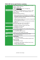
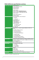
P8H61-MX Series specifications summary CPU Chipset Memory Graphics Expansion slots Storage LAN Audio USB LGA1155 socket for Intel® 3rd/2nd Generation Core™ i7 / i5 / i3 / Pentium® / Celeron® processors Supports 22/32nm CPU *Refer to www.asus.com for Intel® CPU support list. Intel® H61 Express Chipset 2 x DIMMs, max. 16GB DDR3 2200 (O.C.) / 2133 (O.C.) / 2000 (O.C.) / 1866 (O.C.
P8H61-MX Series specifications summary ASUS unique features ASUS MyLogo 2™ ASUS Anti-Surge Protection ASUS UEFI BIOS ASUS EZ Flash 2 ASUS FanXpert ASUS AI Charger (P8H61-MX R2.0 only) ASUS AI Charger+ (P8H61-MX USB3 only) ASUS Q-Fan 2 ASUS CrashFree BIOS 3 ASUS GPU Boost Rear panel ports 1 x PS/2 keyboard / mouse combo port 1 x DVI port 1 x D-Sub port 1 x LAN (RJ-45) port P8H61-MX R2.0: - 6 x USB 2.0/1.1 ports P8H61-MX USB3: - 4 x USB 2.0/1.1 ports - 2 x USB 3.
Chapter 1 Product introduction Thank you for buying an ASUS® P8H61-MX Series motherboard! Before you start installing the motherboard and adding hardware components, check the items in your motherboard package. Refer to page x for the list of included accessories. • If any of the items is damaged or missing, contact your retailer. • ASUS P8H61-MX Series motherboards include P8H61-MX R2.0 and P8H61-MX USB3 models. The layout varies between the two models.
1.2 Motherboard overview Before you install the motherboard, study the configuration of your chassis to ensure that the motherboard fits. Unplug the power cord before installing or removing the motherboard. Failure to do so can cause you physical injury and damage motherboard components. 1.2.1 Placement direction 1.2.2 Screw holes When installing the motherboard, place it into the chassis in the correct orientation.
1.2.3 Motherboard layout 1 2 3 1 4 18.3cm(7.2in) KB_USB56 DVI CPU_FAN AUDIO CHA_FAN EATXPWR LAN_USB12 P8H61-MX R2.0 24.4cm(9.
1 2 3 1 4 18.3cm(7.2in) KB_USB56 DVI CPU_FAN EATXPWR LAN_USB12 ASM 1042 AUDIO CHA_FAN 24.4cm(9.6in) USB3_12 DDR3 DIMM_B1 (64bit, 240-pin module) DDR3 DIMM_A1 (64bit, 240-pin module) LGA1155 VGA ATX12V P8H61-MX USB3 2 PCIEX16 RTL 8111F Lithium Cell CMOS Power Super I/O Intel® H61 PCIEX1_1 SB_PWR SATA3G_1 SATA3G_4 SATA3G_2 SPEAKER USB910 USB78 CLRTC AAFP 5 F_PANEL 11 1-4 SATA3G_3 PCIEX1_2 VIA VT1708S 1.2.
1.3 Central Processing Unit (CPU) The motherboard comes with a surface mount LGA1155 socket designed for Intel® processors. Unplug all power cables before installing the CPU. • Upon purchase of the motherboard, ensure that the PnP cap is on the socket and the socket contacts are not bent. Contact your retailer immediately if the PnP cap is missing, or if you see any damage to the PnP cap/socket contacts/motherboard components.
3. Lift the load lever in the direction of the arrow until the load plate is completely lifted. Load plate 4. Remove the PnP cap from the CPU socket by lifting the tab only. PnP cap 5. Position the CPU over the socket, ensuring that the gold triangle is on the bottom‑left corner of the socket, and then fit the socket alignment keys into the CPU notches. The CPU fits in only one correct orientation.
6. Apply some Thermal Interface Material to the exposed area of the CPU that the heatsink will be in contact with, ensuring that it is spread in an even thin layer. Some heatsinks come with preapplied thermal paste. If so, skip this step. The Thermal Interface Material is toxic and inedible. DO NOT eat it. If it gets into your eyes or touches your skin, wash it off immediately, and seek professional medical help. 7.
1.3.2 Installing the CPU heatsink and fan The Intel® LGA1155 processor requires a specially designed heatsink and fan assembly to ensure optimum thermal condition and performance. • When you buy a boxed Intel® processor, the package includes the CPU fan and heatsink assembly. If you buy a CPU separately, ensure that you use only Intel®‑certified multi‑directional heatsink and fan. • Your Intel® LGA1155 heatsink and fan assembly comes in a push-pin design and requires no tool to install.
3. Connect the CPU fan cable to the connector on the motherboard labeled CPU_FAN. CPU FAN PWM CPU FAN IN CPU FAN PWR GND CPU_FAN P8H61-MX R2.0 P8H61-MX Series CPU fan connector Do not forget to connect the CPU fan connector! Hardware monitoring errors can occur if you fail to plug this connector. 1.3.3 Uninstalling the CPU heatsink and fan To uninstall the CPU heatsink and fan: 1. Disconnect the CPU fan cable from the connector on the motherboard. 2. Rotate each fastener counterclockwise. 3.
4. Carefully remove the heatsink and fan assembly from the motherboard. 5. Rotate each fastener clockwise to ensure correct orientation when reinstalling. 1.4 System memory 1.4.1 Overview DIMM_A1 DIMM_B1 The motherboard comes with two Double Data Rate 3 (DDR3) Dual Inline Memory Modules (DIMM) sockets. A DDR3 module has the same physical dimensions as a DDR2 DIMM but is notched differently to prevent installation on a DDR2 DIMM socket.
1.4.2 Memory configurations You may install 1GB, 2GB, 4GB and 8GB unbuffered non‑ECC DDR3 DIMMs into the DIMM sockets. • You may install varying memory sizes in Channel A and Channel B. The system maps the total size of the lower-sized channel for the dual-channel configuration. Any excess memory from the higher-sized channel is then mapped for single-channel operation. • Always install DIMMs with the same CAS latency.
DDR3-1333 MHz capability Vendors Part No. Size SS/ DS Chip Brand Chip NO. Timing Voltage A-Data AD31333001GOU 1GB SS A-Data AD63I1B0823EV AD31333G001GOU 2GB 3GB(3 x 1GB) SS SS A-Data - AD30908C8D-151C E0906 3CCA-1509A - - A-Data A-Data A-Data AXDU1333GC2G9-2G(XMP) 4GB(2 x 2GB) SS - - A-Data A-Data Apacer Apacer Apacer CORSAIR CORSAIR CORSAIR CORSAIR CORSAIR CORSAIR Crucial Crucial Crucial AD31333G002GMU AD63I1C1624EV 78.A1GC6.9L1 78.A1GC6.9L1 78.B1GDE.
DDR3-1333 MHz capability Vendors Part No.
DDR3-1600 MHz capability Vendors Part NO. Size SS/ DS Chip Brand Chip NO. Timing Voltage G.SKILL G.SKILL G.SKILL F3-12800CL9D-2GBNQ(XMP) F3-12800CL7D-4GBRH(XMP) F3-12800CL7D-4GBECO(XMP) 2GB(2 x 1GB) 4GB(2 x 2GB) 4GB(2 x 2GB) SS SS DS - - 9-9-9-24 7-7-7-24 7-7-8-24 G.SKILL G.SKILL G.SKILL F3-12800CL7D-4GBRM(XMP) F3-12800CL8D-4GBRM(XMP) F3-12800CL9D-4GBECO(XMP) 4GB(2 x 2GB) 4GB(2 x 2GB) 4GB(2 x 2GB) DS DS DS - - 7-8-7-24 8-8-8-24 9-9-9-24 G.SKILL G.SKILL G.SKILL G.
DDR3-1866 MHz capability Vendors A-DATA CORSAIR CORSAIR CORSAIR G.SKILL G.SKILL G.SKILL G.SKILL KINGSTON KINGSTON KINGSTON KINGSTON Chip Chip SS/DS Brand NO. Part No. Size Timing Voltage AX3U1866PB2G8-DP2(XMP) CMT4GX3M2A1866C9(XMP) CMT6GX3MA1866C9(XMP) CMZ8GX3M2A1866C9(XMP) F3-14900CL9Q-16GBZL(XMP1.3) F3-14900CL10Q264GBZLD(XMP1.
DDR3-2200 MHz capability Vendors G.SKILL GEIL GEIL KINGMAX KINGMAX KINGMAX Part No. F3-17600CL8D-4GBPS(XMP) GET34GB2200C9DC(XMP) GET38GB2200C9ADC(XMP) FLKE85F-B8KJAA-FEIS(XMP) FLKE85F-B8KHA EEIH(XMP) FLKE85F-B8KJA FEIH(XMP) Size 4GB(2 x 2GB) 2GB 4GB 2GB 4GB(2 x 2GB) 4GB(2 x 2GB) SS/ DS Chip Brand Chip NO. Timing Voltage DS DS DS DS DS DS - - 8-8-8-24 9-10-9-28 9-11-9-28 - 1.65V 1.65V 1.65V 1.5V-1.7V 1.5V-1.7V SS/ DS Chip Brand Chip NO. Timing Voltage DS - - - 1.
1.4.3 Installing a DIMM Unplug the power supply before adding or removing DIMMs or other system components. Failure to do so can cause severe damage to both the motherboard and the components. 1. Press the retaining clips outward to unlock a DIMM socket. 2. Align a DIMM on the socket such that the notch on the DIMM matches the DIMM slot key on the socket. 2 DIMM notch 1 Unlocked retaining clip DIMM slot key A DIMM is keyed with a notch so that it fits in only one direction.
1.5 Expansion slots In the future, you may need to install expansion cards. The following sub‑sections describe the slots and the expansion cards that they support. Unplug the power cord before adding or removing expansion cards. Failure to do so may cause you physical injury and damage motherboard components. 1.5.1 Installing an expansion card To install an expansion card: 1.
1.6 Jumpers Clear RTC RAM (3-pin CLRTC) This jumper allows you to clear the Real Time Clock (RTC) RAM in CMOS. You can clear the CMOS memory of date, time, and system setup parameters by erasing the CMOS RTC RAM data. The onboard button cell battery powers the RAM data in CMOS, which include system setup information such as system passwords. CLRTC P8H61-MX R2.0 1 2 2 Normal (Default) Clear RTC 3 P8H61-MX Series Clear RTC RAM To erase the RTC RAM: 1.
1.7 Connectors 1.7.1 Rear panel connectors 1 2 10 9 8 7 3 4 6 5 1. PS/2 Keyboard / Mouse Combo port. This port is for a PS/2 keyboard or PS/2 mouse. 2. LAN (RJ-45) port. This port allows Gigabit connection to a Local Area Network (LAN) through a network hub. Refer to the table below for the LAN port LED indications.
6. USB 2.0 ports 1 and 2. These two 4-pin Universal Serial Bus (USB) ports are for USB 2.0/1.1 devices. 7. USB 2.0 ports 3 and 4 (P8H61-MX R2.0 only). These two 4-pin Universal Serial Bus (USB) ports are for USB 2.0 devices. USB 3.0 ports 1 and 2 (P8H61-MX USB3 only). These two 9-pin Universal Serial Bus (USB) ports are for USB 3.0 devices. • DO NOT connect a keyboard / mouse to any USB 3.0 port when installing Windows® operating system. • Due to USB 3.0 controller limitation, USB 3.
• We recommend that you connect a high-definition front panel audio module to this connector to avail of the motherboard’s high-definition audio capability. • If you want to connect a high-definition front panel audio module to this connector, set the Front Panel Type item in the BIOS setup to [HD]. If you want to connect an AC'97 front panel audio module to this connector, set the item to [AC97]. By default, this connector is set to [HD]. See section 2.5.6 Onboard Devices Configuration for details. 2.
3. CPU and chassis fan connectors (4-pin CPU_FAN, 3-pin CHA_FAN) Connect the fan cables to the fan connectors on the motherboard, ensuring that the black wire of each cable matches the ground pin of the connector. CPU FAN PWM CPU FAN IN CPU FAN PWR GND CPU_FAN CHA_FAN P8H61-MX R2.0 Rotation +12V GND P8H61-MX Series Fan connectors Do not forget to connect the fan cables to the fan connectors. Insufficient air flow inside the system may damage the motherboard components.
Never connect a 1394 cable to the USB connectors. Doing so will damage the motherboard! The USB module cable is purchased separately. Intel® H61 Serial ATA 3.0Gb/s connectors (7-pin SATA3G_1~4) These connectors connect to Serial ATA 3.0 Gb/s hard disk drives and optical drives via Serial ATA 3.0 Gb/s signal cables.
6. Speaker connector (4-pin SPEAKER) The 4-pin connector is for the chassis-mounted system warning speaker. The speaker allows you to hear system beeps and warnings. +5V GND GND Speaker Out SPEAKER P8H61-MX R2.0 PIN 1 P8H61-MX Series Speaker Out Connector 7. System panel connector (10-1 pin PANEL) This connector supports several chassis-mounted functions. F_PANEL PLED+ PLEDPWR GND PWR LED PWR BTN HD_LED+ HD_LEDGround Reset PIN 1 P8H61-MX R2.
1.8 Software support 1.8.1 Installing an operating system This motherboard supports Windows® XP / Vista / 7 Operating Systems (OS). Always install the latest OS version and corresponding updates to maximize the features of your hardware. • Motherboard settings and hardware options vary. Refer to your OS documentation for detailed information.
Chapter 2 BIOS information 2.1 Managing and updating your BIOS Save a copy of the original motherboard BIOS file to a USB flash disk in case you need to restore the BIOS in the future. Copy the original motherboard BIOS using the ASUS Update utility. 2.1.1 ASUS Update utility The ASUS Update is a utility that allows you to manage, save, and update the motherboard BIOS in a Windows® environment. • ASUS Update requires an Internet connection either through a network or an Internet Service Provider (ISP).
The ASUS Update utility is capable of updating itself through the Internet. Always update the utility to avail all its features. Updating from a BIOS file a. Select Update BIOS from file, then click Next. b. Locate the BIOS file from the Open window, then click Open. 3. Follow the onscreen instructions to complete the update process. 2.1.2 ASUS EZ Flash 2 The ASUS EZ Flash 2 feature allows you to update the BIOS without using an OS‑based utility.
3. 4. 5. 6. Press to switch to the Drive field. Press the Up/Down arrow keys to find the USB flash disk that contains the latest BIOS, and then press . Press to switch to the Folder Info field. Press the Up/Down arrow keys to find the BIOS file, and then press to perform the BIOS update process. Reboot the system when the update process is done. • This function supports USB flash disks formatted using FAT 16/32 format on a single partition.
3. 4. When the Make Disk menu appears, select the FreeDOS command prompt item by pressing the item number. At the FreeDOS prompt, type d: and press to switch the disk from Drive C (optical drive) to Drive D (USB flash drive). Welcome to FreeDOS (http://www.freedos.org)! C:\>d: D:\> Updating the BIOS file To update the BIOS file using BIOS Updater 1. At the FreeDOS prompt, type bupdater /pc /g and press . D:\>bupdater /pc /g 2. The BIOS Updater screen appears as below.
4. Select Yes and press . When BIOS update is done, press to exit BIOS Updater. Restart your computer. DO NOT shut down or reset the system while updating the BIOS to prevent system boot failure! • For BIOS Updater version 1.04 or later, the utility automatically exits to the DOS prompt after updating BIOS. • Load the BIOS default settings to ensure system compatibility and stability. Select the Load Optimized Defaults item under the Exit menu. Refer to section 2.9 Exit menu for details.
BIOS menu screen The BIOS setup program can be used under two modes: EZ Mode and Advanced Mode. You can change modes from the Exit menu or from the Exit/Advanced Mode button in the EZ Mode/Advanced Mode screen. EZ Mode By default, the EZ Mode screen appears when you enter the BIOS setup program. The EZ Mode provides you an overview of the basic system information, and allows you to select the display language, system performance mode and boot device priority.
Advanced Mode The Advanced Mode provides advanced options for experienced end-users to configure the BIOS settings. The figure below shows an example of the Advanced Mode. Refer to the following sections for the detailed configurations. To access the EZ Mode, click Exit, then select ASUS EZ Mode.
Menu items The highlighted item on the menu bar displays the specific items for that menu. For example, selecting Main shows the Main menu items. The other items (Ai Tweaker, Advanced, Monitor, Boot, Tool, and Exit) on the menu bar have their respective menu items. Back button This button appears when entering a submenu. Press or use the USB mouse to click this button to return to the previous menu screen.
2.3 Main menu The Main menu screen appears when you enter the Advanced Mode of the BIOS Setup program. The Main menu provides you an overview of the basic system information, and allows you to set the system date, time, language, and security settings. 2.3.1 System Language [English] 2.3.2 System Date [Day xx/xx/xxxx] 2.3.3 System Time [xx:xx:xx] 2.3.4 Security Allows you to choose the BIOS language version from the options.
Administrator Password If you have set an administrator password, we recommend that you enter the administrator password for accessing the system. Otherwise, you might be able to see or change only selected fields in the BIOS setup program. To set an administrator password: 1. Select the Administrator Password item and press . 3. Confirm the password when prompted. 2. From the Create New Password box, key in a password, then press . To change an administrator password: 1. 2. 3. 4.
2.4 Ai Tweaker menu The Ai Tweaker menu items allow you to configure overclocking-related items. Be cautious when changing the settings of the Ai Tweaker menu items. Incorrect field values can cause the system to malfunction. • The configuration options for this section vary depending on the CPU and DIMM model you installed on the motherboard. • The item Ai Overclock Tuner will be displayed on the Ai Tweaker menu when an X.M.P.
2.4.2 ASUS MultiCore Enhancement [Enabled] 2.4.3 Memory Frequency [Auto] Allows you to set the memory frequency mode under XMP/Manual/User for maximum performance. Configuration options: [Enabled] [Disabled] Allows you to set the memory operating frequency. Configuration options: [Auto] [DDR3800MHz] [DDR3-1066MHz] [DDR3-1333MHz] [DDR3-1600MHz] [DDR3-1866MHz] [DDR32133MHz] [DDR3-2400MHz] Memory frequency options depend on installed CPU. The configuration options listed above are for a Sandy Bridge CPU.
2.4.7 CPU Power Management The sub-items in this menu allow you to set the CPU ratio and features. CPU Ratio [Auto] Allows you to manually adjust the maximum non-turbo CPU ratio. Use <+> and <-> keys or the numeric keypad to adjust the ratio. The valid value ranges vary according to your CPU model. Enhanced Intel SpeedStep Technology [Enabled] Allows you to enable or disable the Enhanced Intel® SpeedStep Technology (EIST). [Disabled] [Enabled] Disables this function.
2.5 Advanced menu The Advanced menu items allow you to change the settings for the CPU and other system devices. Be cautious when changing the settings of the Advanced menu items. Incorrect field values can cause the system to malfunction.
2.5.1 CPU Configuration The items in this menu show the CPU-related information that the BIOS automatically detects. The items shown in submenu may be different due to the CPU you installed. Scroll down to display the following items: Intel Adaptive Thermal Monitor [Enabled] [Enabled] [Disabled] Enables the overheated CPU to throttle its clock speed to cool down. Disables the CPU thermal monitor function.
Execute Disable Bit [Enabled] [Enabled] [Disabled] Enables the No-Execution Page Protection Technology. Forces the XD feature flag to always return to zero (0). Intel Virtualization Technology [Disabled] [Enabled] [Disabled] Allows a hardware platform to run multiple operating systems separately and simultaneously, enabling one system to virtually function as several systems. Disables this function.
2.5.2 PCH Configuration High Precision Timer [Enabled] Allows you to enable or disable the High Precision Event Timer. Configuration options: [Enabled] [Disabled] Intel(R) Rapid Start Technology Intel(R) Rapid Start Technology [Disabled] Allows you to enable or disable the Intel(R) Rapid Start Technology.Configuration options: [Enabled] [Disabled] The following three items appear only when you set the Intel(R) Rapid Start Technology to [Enabled].
Intel(R) Smart Connect Technology ISCT Configuration [Disabled] Allows you to enable or disable the ISCT configuration. Configuration options: [Enabled] [Disabled] 2.5.3 SATA Configuration While entering Setup, the BIOS automatically detects the presence of SATA devices. The SATA Port items show Not Present if no SATA device is installed to the corresponding SATA port. SATA Mode Selection [IDE Mode] Allows you to set the SATA configuration.
Graphics Configuration Primary Display [Auto] Allows you to decide which graphics controller to use as the primary boot device. Configuration options: [Auto] [iGPU] [PCIE] iGPU Memory [Auto] Allows you to set the iGPU memory size. Configuration options: [Auto] [32M] [64M] [96M] [128M] ~ [448M] [480M] [512M] [1024M] Render Standby [Enabled] Allows you to enable or disable Render Standby by internal graphics devices.
2.5.6 Onboard Devices Configuration HD Audio Controller [Enabled] [Enabled] [Disabled] Enables the High Definition Audio Controller. Disables the controller. The following two items appear only when you set the HD Audio Controller item to [Enabled]. Front Panel Type [HD] Allows you to set the front panel audio connector (AAFP) mode to legacy AC’97 or highdefinition audio depending on the audio standard that the front panel audio module supports.
Power On By PS/2 Keyboard [Disabled] [Disabled] [Space Bar] [Ctrl-Esc] [Power Key] Disables the Power On by a PS/2 keyboard. Sets the Space Bar on the PS/2 keyboard to turn on the system. Sets the Ctrl+Esc key on the PS/2 keyboard to turn on the system. Sets Power key on the PS/2 keyboard to turn on the system. This feature requires an ATX power supply that provides at least 1A on the +5VSB lead. Power On By PS/2 Mouse [Disabled] [Disabled] Disables the Power On by a PS/2 mouse.
2.6 Monitor menu The Monitor menu displays the system temperature/power status, and allows you to change the fan settings.
2.6.1 CPU Temperature / MB Temperature [xxxºC/xxxºF] 2.6.2 CPU / Chassis Fan Speed [xxxx RPM] or [Ignore] / [N/A] 2.6.3 CPU Voltage, 3.3V Voltage, 5V Voltage, 12V Voltage 2.6.4 CPU Q-Fan Control [Enabled] The onboard hardware monitor automatically detects and displays the CPU and motherboard temperatures. Select Ignore if you do not wish to display the detected temperatures. The onboard hardware monitor automatically detects and displays the CPU and chassis fan speeds in rotations per minute (RPM).
2.6.5 Chassis Q-Fan Control [Enabled] [Disabled] [Enabled] Disables the Chassis Q-Fan control feature. Enables the Chassis Q-Fan control feature. Chassis Fan Speed Low Limit [600 RPM] This item appears only when you enable the Chassis Q-Fan Control feature and allows you to disable or set the chassis fan warning speed.
2.7 Boot menu The Boot menu items allow you to change the system boot options. 2.7.1 Bootup NumLock State [On] 2.7.2 Full Screen Logo [Enabled] [On] [Off] [Enabled] [Disabled] Sets the power-on state of the NumLock to [On]. Sets the power-on state of the NumLock to [Off]. Enables the full screen logo display feature. Disables the full screen logo display feature. Set this item to [Enabled] to use the ASUS MyLogo 2™ feature.
2.7.4 [Force BIOS] Option ROM Messages [Force BIOS] [Keep Current] The third-party ROM messages will be forced to display during the boot sequence. The third-party ROM messages will be displayed only if the third-party manufacturer had set the add-on device to do so. 2.7.5 Setup Mode [EZ Mode] 2.7.6 UEFI/Legacy Boot [Enable both UEFI and Legacy] 2.7.8 PCI ROM Priority [Legacy ROM] 2.7.
2.8 Tools menu The Tools menu items allow you to configure options for special functions. Select an item then press to display the submenu. 2.8.1 ASUS EZ Flash Utility Allows you to run ASUS EZ Flash 2. Press [Enter] to launch the ASUS EZ Flash 2 screen. For more details, see section 2.1.2 ASUS EZ Flash 2. 2.8.2 ASUS SPD Information DIMM Slot # [DIMM_A1] Displays the Serial Presence Detect (SPD) information of the DIMM module installed on the selected slot.
2.9 Exit menu The Exit menu items allow you to load the optimal default values for the BIOS items, and save or discard your changes to the BIOS items. You can access the EZ Mode from the Exit menu. Load Optimized Defaults This option allows you to load the default values for each of the parameters on the Setup menus. When you select this option or if you press , a confirmation window appears. Select Yes to load the default values.
Appendices Notices Federal Communications Commission Statement This device complies with Part 15 of the FCC Rules. Operation is subject to the following two conditions: • This device may not cause harmful interference. • This device must accept any interference received including interference that may cause undesired operation. This equipment has been tested and found to comply with the limits for a Class B digital device, pursuant to Part 15 of the FCC Rules.
Canadian Department of Communications Statement This digital apparatus does not exceed the Class B limits for radio noise emissions from digital apparatus set out in the Radio Interference Regulations of the Canadian Department of Communications. This class B digital apparatus complies with Canadian ICES-003.
ASUS contact information ASUSTeK COMPUTER INC. Address Telephone Fax E-mail Web site Technical Support Telephone Online support 15 Li-Te Road, Peitou, Taipei, Taiwan 11259 +886-2-2894-3447 +886-2-2890-7798 info@asus.com.tw www.asus.com.tw +86-21-38429911 support.asus.
A-4 ASUS P8H61-MX Series (510)739-3777/(510)608-4555 800 Corporate Way, Fremont, CA 94539. Asus Computer International Signature : Date : Representative Person’s Name : May , 2012 Steve Chang / President This device complies with part 15 of the FCC Rules. Operation is subject to the following two conditions: (1) This device may not cause harmful interference, and (2) this device must accept any interference received, including interference that may cause undesired operation.