RS700-E7/RS4 1U Rackmount Server User Guide
E7182 First Edition February 2012 Copyright © 2012 ASUSTeK COMPUTER INC. All Rights Reserved. No part of this manual, including the products and software described in it, may be reproduced, transmitted, transcribed, stored in a retrieval system, or translated into any language in any form or by any means, except documentation kept by the purchaser for backup purposes, without the express written permission of ASUSTeK COMPUTER INC. (“ASUS”).
Contents Contents....................................................................................................... iii Notices......................................................................................................... vii Safety information..................................................................................... viii About this guide.......................................................................................... ix Chapter 1: Product introduction 1.
Contents 2.8.5 3.1 3.1.1 3.2 Attaching the fixing latches to the server......................... 3-2 Ball-bearing rail kit items (optional)............................................ 3-5 3.2.1 Attaching the rails to the server....................................... 3-5 3.2.2 Attaching the rack rails..................................................... 3-6 3.2.3 Rackmounting the server................................................. 3-7 4.1 Motherboard layouts.....................................
Contents 5.5 5.6 5.4.7 Onboard LAN Configuration........................................... 5-29 5.4.8 USB Configuration......................................................... 5-30 5.4.9 Trusted Computing......................................................... 5-32 5.4.10 ACPI Settings................................................................. 5-33 5.4.11 WHEA Configuration...................................................... 5-34 5.4.12 APM...........................................
Contents 6.2.8 Enabling WriteCache..................................................... 6-23 6.3 Intel® Rapid Storage Technology enterprise SCU/SATA Option ROM Utility...................................................................... 6-24 6.3.1 Creating a RAID set....................................................... 6-26 6.3.2 Creating a Recovery set................................................ 6-27 6.3.3 Deleting a RAID set....................................................... 6-29 6.3.
Notices Federal Communications Commission Statement This device complies with Part 15 of the FCC Rules. Operation is subject to the following two conditions: • This device may not cause harmful interference, and • This device must accept any interference received including interference that may cause undesired operation. This equipment has been tested and found to comply with the limits for a Class B digital device, pursuant to Part 15 of the FCC Rules.
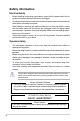
Safety information Electrical Safety • Before installing or removing signal cables, ensure that the power cables for the system unit and all attached devices are unplugged. • To prevent electrical shock hazard, disconnect the power cable from the electrical outlet before relocating the system. • When adding or removing any additional devices to or from the system, ensure that the power cables for the devices are unplugged before the signal cables are connected.
DO NOT throw the motherboard in municipal waste. This product has been designed to enable proper reuse of parts and recycling. This symbol of the crossed out wheeled bin indicates that the product (electrical and electronic equipment) should not be placed in municipal waste. Check local regulations for disposal of electronic products. DO NOT throw the mercury-containing button cell battery in municipal waste.
Conventions To ensure that you perform certain tasks properly, take note of the following symbols used throughout this manual. DANGER/WARNING: Information to prevent injury to yourself when trying to complete a task. CAUTION: Information to prevent damage to the components when trying to complete a task. IMPORTANT: Instructions that you MUST follow to complete a task. NOTE: Tips and additional information to help you complete a task.
This chapter describes the general features of the chassis kit. It includes sections on front panel and rear panel specifications.
1.1 System package contents Check your system package for the following items. Model Name RS700-E7/RS4 Chassis ASUS R12D 1U Rackmount Chassis Motherboard ASUS Z9PP-D24 Server Board Component 2 x800W Redundant Power Supply (varies by territories) 1 x SAS 3.5” HDD Backplane (BP4LX-R10A) 4 x hot-swap 3.
1.3 System specifications The ASUS RS700-E7/RS4 feature the ASUS Z9PP-D24 server board. The server supports Intel® Socket-R LGA2011 Xeon® series processors with EM64T technology, plus other latest technologies through the chipsets onboard. Model Name RS700-E7/RS4 2 x Socket-R (LGA2011) Processor / System Bus QPI 6.4 / 7.2 / 8.
Model Name RS700-E7/RS4 Onboard I/O 5 x RJ-45 ports (1 for ASMB6-iKVM) 4 x USB 2.0 ports (Front x 2, Rear x 2) 1 x VGA port 1 x PS/2 keyboard port 1 x PS/2 mouse port OS Support Windows® Server 2008 R2 Windows® Server 2008 Enterprise 32 / 64-bit Windows® Server 2003 R2 Enterprise 32 / 64-bit RedHat® Enterprise Linux AS5.7, 6.1 32 / 64-bit SuSE® Linux Enterprise Server 11.
1.4 Front panel features The barebone server displays a simple yet stylish front panel with easily accessible features. The power and reset buttons, LED indicators, slim type optical drive, and two USB ports are located on the front panel. Refer to section 1.7.1 Front panel LEDs for the LED descriptions.
1.6 Internal features The barebone server includes the basic components as shown. 1 3 2 2 4 5 1. Power supply and power fan 2. PCI-E G3 x16 slot (x16 link) (FH/HL) 3. PIKE Slot 4. ASUS Z9PP-D24 Server Board 5. System fans 6. SATA/SAS backplane (hidden) 7. 4 x HDD trays 8. Front LED Board (FPB-AR14) 9. Slim-type optical drive 6 7 9 8 The barebone server does not include a floppy disk drive.
1.7 LED information 1.7.1 Front panel LEDs HDD Access LED LAN2 LED LAN1 LED LED Icon Power LED Display status Description ON HDD Access LED Message LED Location LED OFF Blinking OFF Blinking OFF ON OFF Blinking ON LAN LEDs 1.7.
1.7.
This chapter lists the hardware setup procedures that you have to perform when installing or removing system components.
2.1 Chassis cover Removing the rear cover 1. Loosen the two thumbscrews on the rear panel to release the rear cover from the chassis. Thumbscrews 2. Firmly hold the cover and slide it toward the rear panel for about half an inch until it is disengaged from the chassis. 1/2 inch distance 3. 2-2 Lift the cover from the chassis.
2.2 Central Processing Unit (CPU) The motherboard comes with a surface mount LGA2011 socket designed for the Intel® Xeon E5-2600 family processor. 2.2.1 • Upon purchase of the motherboard, ensure that the PnP cap is on the socket and the socket contacts are not bent. Contact your retailer immediately if the PnP cap is missing, or if you see any damage to the PnP cap/socket contacts/motherboard components. ASUS will shoulder the cost of repair only if the damage is shipment/transit-related.
2. Press the left load lever with your thumb (A), then move it to the left (B) until it is released from the retention tab. To prevent damage to the socket pins, do not remove the PnP cap unless you are installing a CPU. 3. Slightly lift the load lever in the direction of the arrow. 4. Press the right load lever with your thumb (C), then move it to the right (D) until it is released from the retention tab. Lift the load lever in the direction of the arrow (E).
5. Push the left load lever (F) to lift the load plate (G). F G 6. Position the CPU over the socket, ensuring that the triangle mark is on the top‑right corner of the socket. Triangle mark The CPU fits in only one correct orientation. DO NOT force the CPU into the socket to prevent bending the connectors on the socket and damaging the CPU! 7. Remove the PnP cap (H) from the CPU socket and close the load plate (I).
8. Push down the right load lever (J), ensuring that the edge of the load plate is fixed by the lever (K). K J 9. Insert the right load lever under the retention tab. 10. Push down the left load lever (L), and then insert the lever under the retention tab (M).
11. Apply some Thermal Interface Material to the exposed area of the CPU that the heatsink will be in contact with, ensuring that it is spread in an even thin layer. Some heatsinks come with preapplied thermal paste. If so, skip this step. The Thermal Interface Material is toxic and inedible. DO NOT eat it. If it gets into your eyes or touches your skin, wash it off immediately, and seek professional medical help.
2.2.2 Installing the CPU heatsink To install the CPU heatsink: 1. Place the heatsink on top of the installed CPU, ensuring that the four fasteners match the holes on the motherboard. 2. Twist each of the four screws with a Philips (cross) screwdriver just enough to attach the heatsink to the motherboard. When the four screws are attached, tighten them one by one to completely secure the heatsink. A B 2-8 B A Tighten the four heatsink screws in a diagonal sequence.
2.3 System memory 2.3.1 Overview The motherboard comes with 12 (per CPU) Double Data Rate 3 (DDR3) Dual Inline Memory Modules (DIMM) sockets. A DDR3 module has the same physical dimensions as a DDR2 DIMM but is notched differently to prevent installation on a DDR2 DIMM socket. DDR3 modules are developed for better performance with less power consumption.
2 CPU Configuration (Single Rank, Dual Rank) DIMM_A3 DIMM_A2 DIMM_A1 DIMM_B3 V 1 DIMMs V 2 DIMMs V 4 DIMMs V 8 DIMMs V V 12 DIMMs V V 16 DIMMs V V V V 20 DIMMs V V V V 24 DIMMs 2 CPU Configuration (Single Rank, Dual Rank) DIMM_C3 DIMM_C2 DIMM_C1 DIMM_D3 1 DIMMs 2 DIMMs V 4 DIMMs V 8 DIMMs V V 12 DIMMs V V 16 DIMMs V V V V 20 DIMMs V V V V 24 DIMMs 2 CPU Configuration (Single Rank, Dual Rank) DIMM_E3 DIMM_E2 DIMM_E1 DIMM_F3 1 DIMMs 2 DIMMs 4 DIMMs V 8 DIMMs V 12 DIMMs V V 16 DIMMs V V 20 DIMMs V V V V 24 DIM
2.3.3 Installing a DIMM on a single clip DIMM socket 1. Unlock a DIMM socket by pressing the retaining clip outward. 2. Align a DIMM on the socket such that the notch on the DIMM matches the DIMM slot key on the socket. DIMM notch 1 2 DIMM slot key Unlocked retaining clip A DIMM is keyed with a notch so that it fits in only one direction. DO NOT force a DIMM into a socket in the wrong direction to avoid damaging the DIMM. 3.
2.4 Hard disk drives The system supports four hot-swap SATAII/SAS hard disk drives. The hard disk drive installed on the drive tray connects to the motherboard SATAII/SAS ports via the SATAII/SAS backplane. To install a hot-swap SATAII/SAS HDD: 2-12 1. Release a drive tray by pushing the spring lock to the right, then pulling the tray lever outward. The drive tray ejects slightly after you pull out the lever. 2. Firmly hold the tray lever and pull the drive tray out of the bay. 3.
5. Carefully insert the drive tray and push it all the way to the depth of the bay until just a small fraction of the tray edge protrudes. When installed, the SATAII/SAS connector on the drive connects to the SATAII/ SAS interface on the backplane. 6. Push the tray lever until it clicks, and secures the drive tray in place. The drive tray is correctly placed when its front edge aligns with the bay edge. 7. Repeat steps 1 to 6 if you wish to install a second SATAII/SAS drive.
2.5 Expansion slot 2.5.1 Installing an expansion card to the riser card bracket The barebone server comes with two riser card brackets. You need to remove the bracket if you want to install PCI Express x8 or x16 expansion cards. To install a PCI Express x8 or x16 card in PCIE1 slot: 1. Firmly hold the riser card bracket, then pull it up to detach it from the PCI Express x16 slot on the motherboard. 2. Place the riser card bracket on a flat and stable surface, then remove the screw from the slot bay.
To reinstall the riser card bracket in PCIE1 slot: 1. Align the riser card bracket with the cards to the PCI Express x16 slot on the motherboard. 2. Press the riser card bracket until the golden connectors completely fit the slot and the bracket aligns with the rear panel. 3. Connect the cable(s) to the card, if applicable. To install a PCI Express x8 or x16 card in PCIE2 slot: 1. Firmly hold the riser card bracket, then pull it up to detach it from the PCI Express x16 slot on the motherboard. 2.
3. Install a PCI Express x8 or x16 card to the bracket as shown, then secure the card with a screw. To reinstall the riser card bracket in PCIE2 slot: 2-16 1. Align the riser card bracket with the cards to the PCI Express x16 slot on the motherboard. 2. Press the riser card bracket until the golden connectors completely fit the slot and the bracket aligns with the rear panel. 3. Connect the cable(s) to the card, if applicable.
2.5.2 Configuring an expansion card After installing the expansion card, configure the it by adjusting the software settings. 1. Turn on the system and change the necessary BIOS settings, if any. See Chapter 5 for information on BIOS setup. 2. Assign an IRQ to the card. Refer to the following tables. 3. Install the software drivers for the expansion card.
2.6 Cable connections • • The bundled system cables are pre-connected before shipment. You do not need to disconnect these cables unless you will remove pre‑installed components to install additional devices. Refer to Chapter 4 for detailed information on the connectors. 2 4 3 4 10 11 12 13 4 4 4 Pre-connected system cables 1 4 1 6 5 7 8 9 4 4 1. 2. 3. 4. 5. 6. 7. 8. 9. 10. 11.
2.7 SATAII/SAS backplane cabling SAS_SGPIO_CON1 connector* Connects a 8-pin plug from power supply SGPIO_SEL jumper: pins 1-2 (Onboard) pins 2-3 (Add-on card) Connects the data cables connected to the motherboard Connect the SATAII/SAS HDDs * For PIKE RAID solution, ensure to connect SAS_SGPIO_CON1 to the SGPIO1 connector on the motherboard.
2.8 Removable/optional components You may need to remove previously installed system components when installing or removing system devices. Or you may need to install the optional components into the system. This section tells how to remove/install the following components: 1. System fans 2. Redundant power supply module 3. Slim type optical drive (optional) 4. Intel® ASRK module (optional) 5. ASUS PIKE RAID card (optional) Ensure that the system is turned off before removing any components. 2.
2.8.2 Redundant power supply module To replace a failed redundant power supply module 1. Lift up the power supply module lever. 2. Hold the power supply module lever and press the PSU latch. Firmly pull the power supply module out of the system chassis. 3. 4. Firmly push the new power supply module into the chassis until the latch locks to the server chassis.
2.8.3 Replacing optical drive (optional) This server system supports a slim-type optical disk drive. Follow the steps below to replace the optical disk drive. 2-22 1. Remove the screw that secures the optical drive. Keep the screw for reassembly. 2. Remove the SATAII/SAS drive tray by pushing the spring lock to the right, then pulling the tray lever outward. The drive tray ejects slightly after you pull out the lever. 3. Firmly hold the tray lever and pull the drive tray out of the bay. 4.
2.8.4 Connecting the Intel® ASRK Module (Optional) Follow the steps below to connect the ASRK Module to the connector on your motherboard. 1. Locate the ASRK connector on the motherboard. 2. Connect the ASRK module to the connector. • For detail of Intel® Rapid Storage Technology utility, please refer to Chapter 6 RAID Configuration. • The upgrade ASRK kit support HDD 1 - HDD 4 (ISAS1) only.
2.8.5 Installing ASUS PIKE RAID card (optional) Follow the steps below to install an optional ASUS RAID card on your motherboard. 1. Remove the four screws that secure the outer heatsink on the front of the PIKE RAID card and detach the heatsink. DO NOT remove the inner heatsink from the PIKE RAID card. 2. Locate the PIKE RAID card slots (PIKE1/PIKE2) on the motherboard. 3. Remove the screw beside the PIKE1 slot on the motherboard. Keep it for reassembly. 4.
5. Secure the RAID card with the screw that you removed earlier. 6. Disconnect the data cable from ISATA1 and connect it to the PSAS1 connector. 7. Ensure that the SGPIO1_SEL jumper is set to pins 2-3. Refer to 2.7 SATAII/SAS backplane cabling on page 2-19 for the jumper setting details. When using a PIKE RAID card, ensure that the data cables are connected to the PSAS1. The heatsink on PIKE 2108 Series might interfere with the components on the expansion card.
2-26 Chapter 2: Hardware setup
This chapter describes how to install the optional components and devices into the barebone server.
3.1 Friction Rail Kit Installation Guide Your friction rail kit package contains: • One pair of rack rails • One pair of fixing latches • 4 latch screws, 4 rail screws and 4 rail washers Rail Washers Rail screws Latch screws Front end 3.1.1 1. Fixing latches Rack rails Rear end Attaching the fixing latches to the server Secure the two fixing latches to the two sides of the server with the four latch screws. Fixing latch The locations of the screw holes vary with different server models.
2. Select a 1U space on the rack where you want to install the rack rail. A 1U space consists of three square mounting holes with two thin lips on the top and the bottom, as shown in the right figure. 3. Adjust the rack rail to fit the depth of the rack. 4. From inside the rack, place the rear rail hook on the bottom thin lip of the rear mounting hole, and then place the front rail hook on the bottom thin lip of the front mounting hole, as shown in the right figure. 5.
7. When mounting the server to the rack, ensure to include the side knots on the two sides of the server in the rack rail holders, as shown in the right figure. Do not install the rail kit in the following situation: DO NOT place the rail hook on a thick lip of the mounting hole. 3-4 DO NOT install the rail to the outer side of the server rack.
3.2 Ball-bearing rail kit items (optional) Your rackmount rail kit package contains: • two pair of server rails (for the server) • two pairs of rack rails (for the rack) • Nut-and-bolt type screws Nuts and screws 3.2.1 Rear end Front end Rack rails Attaching the rails to the server To attach the server rails: 1. Attach the front end of the server rail to the side of the chassis, matching each of the three hooks to the holes on the rail.
3. Attach the rear end of the server rail to the side of the chassis, matching each of the two hooks to the holes on the rail. Then slide the rail toward the front panel until it locks in place. 4. Secure the rear end of the server rail to the side of the chassis with one screw. 5. Repeat steps 1 to 4 to attach the second server rail to the other side of the chassis. 3.2.2 Attaching the rack rails To attach the rack rails: 3-6 1.
3.2.3 Rackmounting the server To mount the server to the rack: 1. Align the server rails with the rack rails, then push the server all the way to the depth of the rack. 2. Tighten the two rack screws to secure the server in place. To uninstall the server from the rack: 1. Loosen the rack screws that secured the server to the rack. 2. Pull the server from the rack. Remember to press the latches on both sides to release the server from the rack.
3-8 Chapter 3: Installation options
This chapter includes the motherboard layout, and brief descriptions of the jumpers and internal connectors.
4.
Layout contents Jumpers Page 1. Clear RTC RAM (CLRTC1) 4-4 2. VGA controller setting (3-pin VGA_SW1) 4-5 3. LAN controller setting (3-pin LAN_SW1) 4-5 4. RAID configuration utility selection (3-pin RAID_SEL1) 4-6 5. ME firmware force recovery setting (3-pin ME_RCVR1) 4-6 Internal connectors Page 1. Serial ATA connectors (7-pin SATA1–2 [blue]) 4-8 2. ISAS1 and ISATA1 connectors 4-8 3. PSAS 1 and 2 connectors 4-9 4. Hard disk activity LED connector (4-pin HDLED1) 4-9 5.
4.2 1. Jumpers Clear RTC RAM (CLRTC1) This jumper allows you to clear the Real Time Clock (RTC) RAM in CMOS. You can clear the CMOS memory of date, time, and system setup parameters by erasing the CMOS RTC RAM data. The onboard button cell battery powers the RAM data in CMOS, which include system setup information such as system passwords. To erase the RTC RAM: 1. Turn OFF the computer and unplug the power cord. 2. Move the jumper cap from pins 1–2 (default) to pins 2–3.
2. VGA controller setting (3-pin VGA_SW1) Z9PP-D24 This jumper allows you to enable or disable the onboard VGA controller. Set to pins 1–2 to activate the VGA feature. VGA_SW1 3 2 2 1 PIN1 PIN1 Enable (Default) Disable Z9PP-D24 VGA setting 3. LAN controller setting (3-pin LAN_SW1) These jumpers allow you to enable or disable the onboard Intel® I350-AM4 Gigabit LAN1/2/3/4 controller. Set to pins 1–2 to activate the Gigabit LAN feature.
4. RAID configuration utility selection (3-pin RAID_SEL1) This jumper allows you to select the RAID configuration utility to use when you create disk arrays. Place the jumper caps over pins 1–2 if you want to use the LSI MegaRAID software RAID Setup Utility (default); otherwise, place the jumper caps to pins 2–3 to use the Intel® Rapid Storage Technology Enterprise. Z9PP-D24 RAID_SEL1 1 2 PIN1 2 3 PIN1 INTEL LSI RAID (Default) Z9PP-D24 RAID setting 5.
6. Baseboard Management Controller (BMC) Setting (3-pin BMC_EN1) Z9PP-D24 This jumper allows you to enable (default) or disable on-board BMC.
4.3 Serial ATA connectors (7-pin SATA1–2 [Blue]) These connectors, controlled by Intel® C602 chipset, are for the Serial ATA signal cables for Serial ATA hard disk drives (SATA 5 connector for optical drive use by default). Z9PP-D24 1. Internal connectors GN4 RSATA_1TXP2 RSATA_TXN2 GND RSATA_RXP2 RSATA_RXN2 GND SATA6 GND RSATA_TXP1 RSATA_TXN1 GND RSATA_RXP1 RSATA_RXN1 GND SATA5 Z9PP-D24 SATA connectors 2.
3. PSAS 1 and 2 connectors Supported by the ASUS PIKE card, these connectors are for the SAS signal cables for SAS hard disk drives that allows up to 6Gb/s of data transfer rate. After installing the PIKE RAID card and SAS hard disk drives, ensure that the SAS signal cable is connected to the PSAS1 port to create a RAID configuration. Z9PP-D24 Also, ensure that the SGPIO_SEL1 jumper on the backplane is set to pins 2-3 (Default). Refer to 2.7 SATAII/SAS backplane cabling for details.
5. USB connectors (10-1 pin USB34, USB56, Type A USB10) USB+5V USB_P6USB_P6+ GND NC The USB34 and USB56 connectors are for USB 2.0 ports. Connect the USB module cable to the connectors, and then install the module to a slot opening at the back of the system chassis. The USB10 connector is for a A-type internal USB 2.0 device. The USB connectors comply with USB 2.0 specification that supports up to 480 Mbps connection speed.
7. System fan connectors (4-pin FAN1/2/3/4/5/6/7/8) The fan connectors support cooling fans of 0.8A–1.0A (12 W max.) or a total of 6.4 A–8.0 A (96 W max.) at +12V. Connect the fan cables to the fan connectors on the motherboard, making sure that the black wire of each cable matches the ground pin of the connector. DO NOT forget to connect the fan cables to the fan connectors. Insufficient air flow inside the system may damage the motherboard components.
9. System panel connector (20-pin PANEL1 [white]) Z9PP-D24 This connector supports several chassis-mounted functions. SPEAKER PLED+ NC PLEDMLED+ MLEDNC +5V Ground Ground Speaker PLED PANEL1 IDE_LED NMIBTN# Ground PWR Ground NC Reset Ground IDE_LED+ IDE_LED- PIN 1 PWRSW RESET Z9PP-D24 System panel connector 4-12 1. System power LED (3-pin PLED) This 3-pin connector is for the system power LED. Connect the chassis power LED cable to this connector.
4.4 1. Internal LEDs Standby Power LED Z9PP-D24 The motherboard comes with a standby power LED. The green LED lights up to indicate that the system is ON, in sleep mode, or in soft-off mode. This is a reminder that you should shut down the system and unplug the power cable before removing or plugging in any motherboard component. The illustration below shows the location of the onboard LED. SB_PWR ON Standy Power OFF Powered Off Z9PP-D24 Onboard LED 2.
3. DIMM warning LED (ERR_DIMMA1-3, ERR_DIMMB1-3, ERR_DIMMC1-3, ERR_DIMMD1-4, ERR_DIMME1-3, ERR_DIMMF1-3, ERR_DIMMG1-3, ERR_DIMMH1-3) Z9PP-D24 The DIMM warning LEDs light up to indicate that an impending failure of the corresponding DIMM. Z9PP-D24 ERR DIMM LED 4. BMC LED (BMC_LED) Z9PP-D24 The BMC LED light up to indicate that enabled the on-board BMC.
This chapter tells how to change the system settings through the BIOS Setup menus. Detailed descriptions of the BIOS parameters are also provided.
5.1 Managing and updating your BIOS The following utilities allow you to manage and update the motherboard Basic Input/Output System (BIOS) setup: 1. ASUS CrashFree BIOS 3 (To recover the BIOS using a bootable USB flash disk drive when the BIOS file fails or gets corrupted.) 2. ASUS EZ Flash 2 (Updates the BIOS using a USB flash disk.) 3. BUPDATER utility (Updates the BIOS in DOS mode using a bootable USB flash disk drive.) Refer to the corresponding sections for details on these utilities.
5.1.2 ASUS EZ Flash 2 Utility The ASUS EZ Flash 2 Utility feature allows you to update the BIOS without having to use a DOS‑based utility. Before you start using this utility, download the latest BIOS from the ASUS website at www.asus.com. To update the BIOS using EZ Flash 2 Utility 1. 2. Insert the USB flash disk that contains the latest BIOS file to the USB port. Enter the BIOS setup program. Go to the Tool menu to select ASUS EZ Flash 2 Utility and press to enable it.
• This function can support devices such as a USB flash disk with FAT 32/16 format and single partition only. • DO NOT shut down or reset the system while updating the BIOS to prevent system boot failure! Ensure to load the BIOS default settings to ensure system compatibility and stability. Press and select Yes to load the BIOS default settings. 5.1.3 BUPDATER utility The succeeding BIOS screens are for reference only. The actual BIOS screen displays may not be the same as shown.
The utility verifies the file, then starts updating the BIOS file. ASUSTek BIOS Update for DOS V1.06 (09/08/04) FLASH TYPE: MXIC 25L1605A Update ROM Current ROM BOARD: Z9PP-D24 BOARD: Z9PP-D24 VER: 0203 VER: 0206 DATE: 08/24/2011 DATE: 09/30/2011 PATH: WARNING! Do not turn off power during flash BIOS Note W r i t i n g B I O S : DO NOT shut down or reset the system while updating the BIOS to prevent system boot failure! 5.
5.2 BIOS setup program This motherboard supports a programmable firmware chip that you can update using the provided utility described in section 4.1 Managing and updating your BIOS. Use the BIOS Setup program when you are installing a motherboard, reconfiguring your system, or prompted to “Run Setup.” This section explains how to configure your system using this utility. Even if you are not prompted to use the Setup program, you can change the configuration of your computer in the future.
5.2.1 BIOS menu screen Menu items Main Menu bar Configuration fields General help Aptio Setup Utility - Copyright (C) 2011 American Megatrends, Inc. Advanced Server Mgmt Event Logs Boot Monitor Security Tool Exit BIOS Information BIOS Vendor Core Version Compliancy BIOS Version Build Date American Megatrends 4.6.4.1 UEFI 2.1; PI 0.
5.2.3 Menu items The highlighted item on the menu bar displays the specific items for that menu. For example, selecting Main shows the Main menu items. The other items (Event Logs, Advanced, Monitor, Boot, Tool, and Exit) on the menu bar have their respective menu items. 5.2.4 Submenu items A solid triangle before each item on any menu screen means that the item has a submenu. To display the submenu, select the item and press . 5.2.
5.3 Main menu When you enter the BIOS Setup program, the Main menu screen appears. The Main menu provides you an overview of the basic system information, and allows you to set the system date, time, language, and security settings. Main Aptio Setup Utility - Copyright (C) 2011 American Megatrends, Inc. Advanced Server Mgmt Event Logs Boot Monitor Security Tool Exit BIOS Information BIOS Vendor Core Version Compliancy BIOS Version Build Date American Megatrends 4.6.4.1 UEFI 2.1; PI 0.
5.4 Advanced menu The Advanced menu items allow you to change the settings for the CPU and other system devices. Take caution when changing the settings of the Advanced menu items. Incorrect field values can cause the system to malfunction. Main Aptio Setup Utility - Copyright (C) 2011 American Megatrends, Inc.
Socket 1 CPU Information Enter to view socket soecific CPU Information. Aptio Setup Utility - Copyright (C) 2011 American Megatrends, Inc. Advanced Enter to view socket soecific CPU Information. Socket 1 CPU Information Genuine Intel(R) CPU @ 2.
Adjacent Cache Line Prefetch [Enabled] This Item allows you to turn on/off prefetching of adjacent cache lines. Configuration options: [Disabled] [Enabled] DCU Streamer Prefetcher [Enabled] This Item allows you to enabled/disabled L1 data prefetcher. Configuration options: [Disabled] [Enabled] Intel Virtualization Technology [Enabled] When enabled this item, a VMM can utilize the additional hardware capabilities provided by Vanderpool Technology. Configuration options: [Disabled] [Enabled] 5.4.
CPU C3 Report [Disabled] This item allows you to enabled/disabled CPU C3(ACPI C2) report. Configuration options: [Disabled] [Enabled] CPU C6 Report [Enabled] This item allows you to enabled/disabled CPU C6(ACPI C3) report. Configuration options: [Disabled] [Enabled] CPU C7 Report [Disabled] This item allows you to enabled/disabled CPU C7(ACPI C3) report. Configuration options: [Disabled] [Enabled] Package C State limit [C6] This item allows you to set package C State limit.
5.4.3 Chipset Configuration Aptio Setup Utility - Copyright (C) 2011 American Megatrends, Inc. Advanced QPI Configuration Memory Configuration CPU II0 Bridge Configuration PCH Configuration Intel(R) VT for Directed I/O Configuration QPI Configuration Page QPI Configuration Aptio Setup Utility - Copyright (C) 2011 American Megatrends, Inc.
Memory Configuration Aptio Setup Utility - Copyright (C) 2011 American Megatrends, Inc.
Patrol Scrub [Disabled] Allows to Enable/Disable Patrol Scrub. Configuration options: [Disabled] [Enabled] Demand Scrub [Enabled] Allows to Enabled/Disabled demand scrubing feature. Configuration options: [Enabled] [Disabled] Data Scrambling [Enabled] Allows to Enabled/Disabled data scrambling. Configuration options: [Enabled] [Disabled] Device Tagging [Disabled] Allows to Enabled/Disabled device tagging.
DIMM Information Aptio Setup Utility - Copyright (C) 2011 American Megatrends, Inc.
Gen3 Equalization WA’s [Disabled] Support for Gen3 equalization workarounds mentioned in SMB_BSU Version 0.83. Configuration options: [Enabled] [Disabled] IOH Resource Selection Type [Auto] Allows to select auto/manual. When auto option is selected PCI resource allocation across multiple IOHs is optimized automatically based on the PCI device present. With manual option user can force the PCI resource allocation across multiple IOHs based on the ratio selected.
PORT 3C Link Speed [Gen2] Select target link speed Gen1, Gen2 or Gen3. Configuration options: [Gen1] [Gen2] [Gen3] IOH1 PCIe port Bifurcation Control This item appears only when you installed CPU2 on the motherboard. PCH Configuration Aptio Setup Utility - Copyright (C) 2011 American Megatrends, Inc.
SCU devices [Enabled] Allows to enabled/disabled Patsburg SCU devices. Configuration options: [Enabled] [Disabled] Onboard SAS Oprom [Enabled] Allows to enabled/disabled onboard SAS option rom if Launch Storage Oprom is enabled. Configuration options: [Disabled] [Enabled] Onboard SATA RAID Oprom [Enabled] Allows to enabled/disabled onboard SATA RAID option rom if Launch Storage Oprom is enabled.
The following item appears only when you set Alert Enable Lock to [Enabled]. PCH Alert [Disabled] Allows to enabled/disabled PCH Alert pin. Configuration options: [Disabled] [Enabled] DIMM Alert [Disabled] Allows to enabled/disabled DIMM Alert pin. Configuration options: [Disabled] [Enabled] Intel(R) VT for Directed I/O Configuration Aptio Setup Utility - Copyright (C) 2011 American Megatrends, Inc. Advanced Intel(R) VT-d [Disabled] Enables or Disables BIOS ACPI Auto Configuration.
5.4.4 PCH SATA Configuration Aptio Setup Utility - Copyright (C) 2011 American Megatrends, Inc. Advanced SATA SATA SATA SATA SATA SATA Port1 Port2 Port3 Port4 Port5 Port6 Not Present ASUS DWR ATAPI WDC WD800JD(80.0GB) Not Present Not Present Not Present SATA Mode Serial-ATA Controller 0 Serial-ATA Controller 1 S.M.A.R.T. Status Check (1)IDE Mode. (2)AHCI Mode. (3)RAID Mode. [IDE Mode] [Enhanced] [Enhanced] [Enabled] →←: Select Screen ↑↓: Select Item Enter: Select Item +/-: Change Opt.
S.M.A.R.T. Status Check [Enabled] S.M.A.R.T. (Self-Monitoring, Analysis and Reporting Technology) is a monitor system. When read/write of your hard disk errors occur, this feature allows the hard disk to report warning messages during the POST. Configuration options: [Enabled] [Disabled] 5.4.5 PCH SCU SAS Configuration The PCH SCU SAS configuration items appears only when you installed the ASRK Module (optional) on the motherboard. 5.4.
VGA Palette Snoop [Disabled] Enables or disables VGA pallette registers snooping. Configuration options: [Disabled] [Enabled] PERR# Generation [Disabled] Enables or disables PCI device to generate PERR#. Configuration options: [Disabled] [Enabled] SERR# Generation [Disabled] Enables or disables PCI device to generate SERR#. Configuration options: [Disabled] [Enabled] PCI Express Settings Aptio Setup Utility - Copyright (C) 2011 American Megatrends, Inc.
Maximum Payload [Auto] Set Maximum Payload of PCI Express device or allow system BIOS to select the value. Configuration options: [Auto] [128 Bytes] [256 Bytes] [512 Bytes] [1024 Bytes] [2048 Bytes] [4096 Bytes] Maximum Read Request [Auto] Set Maximum Read Request of PCI Express device or allow system BIOS to select the value.
PCI Express GEN2 Device Register Settings Aptio Setup Utility - Copyright (C) 2011 American Megatrends, Inc.
ID0 Completion Enable [Disabled] If supported by hardware and set to ‘Enabled’, this permits setting the number of ID-Based Ordering (ID0) bit (Attribute [2]) requests to be initiated. Configuration options: [Disabled] [Enabled] LTR Mechanism Enable [Disabled] If supported by hardware and set to ‘Enabled’, this enables the Latency Tolerance Reporting (LTR) Mechanism.
PCIE Slot Option Rom Configuration Aptio Setup Utility - Copyright (C) 2011 American Megatrends, Inc. Advanced Legacy 0pROM Support Launch Storage 0pROM [Enabled] PCIE1 PCIE2 PCIE3 PCIE4 PCIE5 [Enabled] [Enabled] [Enabled] [Enabled] [Enabled] Option Option Option Option Option Rom Rom Rom Rom Rom Enables or disables boot option for legacy mass storage device with option ROM. →←: Select Screen ↑↓: Select Item Enter: Select Item +/-: Change Opt.
5.4.7 Onboard LAN Configuration Aptio Setup Utility - Copyright (C) 2011 American Megatrends, Inc. Advanced Intel LAN Enable/Disable.
Intel LAN4 Enable [Enabled] Enables or disables Intel LAN1 function. Configuration options: [Disabled] [Enabled] LAN4 Option ROM Support [Enabled] Configuration options: [Disabled] [Enabled] 5.4.8 USB Configuration Aptio Setup Utility - Copyright (C) 2011 American Megatrends, Inc.
Device power-up delay [Auto] Maximum time the device will take before it property reports itself to the Host Controller. ‘Auto’ uses default valus: for a Root port it is 100ms, for a Hub port the delay is taken from Hub descriptor. Configuration options: [Auto] [Manual] The following item appears only when you set Device power-up delay to [Manual]. Mass Storage Devices: AMI Virtual CDROM0 1.
USB Ports Configuration Aptio Setup Utility - Copyright (C) 2011 American Megatrends, Inc. Advanced EHCI Controller 1 EHCI Controller 2 [Enabled] [Enabled] Rear USB #1 Rear USB #2 Onboard USB #3 Onboard USB #4 Onboard USB #5 Onboard USB #6 Onboard USB #10 [Enabled] [Enabled] [Enabled] [Enabled] [Enabled] [Enabled] [Enabled] Enable/Disable USB 2.0 (EHCI) Support. →←: Select Screen ↑↓: Select Item Enter: Select Item +/-: Change Opt.
5.4.10 ACPI Settings Aptio Setup Utility - Copyright (C) 2011 American Megatrends, Inc. Advanced ACPI Settings Enable ACPI Auto Configuration [Disabled] Enables or Disables BIOS ACPI Auto Configuration. Enabled Hibernation [Enabled] ACPI Sleep State [S1 (CPU Stop Clock)] Lock Legacy Resources [Disabled] Enable ACPI Auto Configuration [Disabled] Allows you to enable or disable BIOS ACPI Auto Configuration.
5.4.11 WHEA Configuration Aptio Setup Utility - Copyright (C) 2011 American Megatrends, Inc. Advanced WHEA Support [Enabled] Enable or disable Windows Hardware Error Architecture. WHEA Support [Enabled] Allows you to enable or disable the Windows Hardware Error Architecture support. Configuration options: [Disabled] [Enabled] 5.4.12 APM Aptio Setup Utility - Copyright (C) 2011 American Megatrends, Inc.
5.4.13 Serial Port Console Redirection Aptio Setup Utility - Copyright (C) 2011 American Megatrends, Inc. Advanced COM1 Console Redirection Console Redirection Settings [Disabled] COM2 Console Redirection Console Redirection Settings [Disabled] Serial Port for Out-of-Band Management/ Windows Emergency Management Services (EMS) Console Redirection [Disabled] Console Redirection Settings Consloe Redirection Enable or Disable.
Data Bits [8] Configuration options: [7] [8] Parity [None] A parity bit can be sent with the data bits to detect some transmission errors. [Mark] and [Space] parity do not allow for error detection. [Even] parity bit is 0 if the num of 1’s in the data bits is even [Odd] parity bit is 0 if num of 1’s in the data bits is odd [Mark] parity bit is always 1 [Space] parity bit is always 0 Stop Bits [1] Stop bits indicate the end of a serial data packet. (A start bit indicates the beginning.
Serial Port for Out-of-Band Management/ Windows Emergency Management Services (EMS) Console Redirection [Disabled] Enables or disables the console redirection feature. Configuration options: [Disabled] [Enabled] The following item appears only when you set Consloe Redirection to [Enabled]. Console Redirection Settings Out-of-Band Mgmt Port [COM1] Microsoft Windows Emergency Management Services (EMS) allow for remote management of a Windows Server OS through a serial port.
5.4.14 ME Subsystem Aptio Setup Utility - Copyright (C) 2011 American Megatrends, Inc. Advanced Intel ME Subsystem Configuration ME Subsystem [Enabled] ME BIOS Interface Version 1.2 ME Version 2.1.5.43 ME FW Status Value : ME FW State ME Subsystem Help.
Serial Port [Enabled] Allows to enables or disables the serial port. Configuration options: [Disabled] [Enabled] Device Mode [Standard Serial Port Mode] Allows to change the serial port mode. Configuration options: [Standard Serial Port Mode] 5.4.16 Runtime Error Logging Aptio Setup Utility - Copyright (C) 2011 American Megatrends, Inc. Advanced Runtime Error Logging Support [Disabled] Runtime Error Logging Support [Disabled] This item allows you to enables or disables Runtime Error Logging Support.
5.5 Server Mgmt menu The Server Mgmt menu displays the server mgmt status, and allows you to change the settings. Main Aptio Setup Utility - Copyright (C) 2011 American Megatrends, Inc. Advanced Server Mgmt Event Logs Boot Monitor Security Tool Exit BMC Firmware: 1.
O/S Wtd Timer Policy [Reset] Allows to configure how the system should respond if the OS Boot Watchdog Timer expires. Not available if O/S Boot Watchdog Timer is disabled. Configuration options: [Do Nothing] [Reset] [Power Down] 5.5.1 System Event Log Aptio Setup Utility - Copyright (C) 2011 American Megatrends, Inc.
5.5.2 BMC network configuration Aptio Setup Utility - Copyright (C) 2011 American Megatrends, Inc. Server Mgmt BMC network configuration DM_KAN1 DM_LAN1 IP Address in BMC: DM_LAN1 Subnet Mask in BMC: DM_LAN1 Gateway Address in BMC : DM_LAN1 MAC Address in BMC: DM_LAN1 Address Source in BMC: Configuration Address source 192.168.001.001 255.255.255.000 000.000.000.000 00.CE.01.87.72.
5.6 Event Logs menu The Event Logs allows you to change or view the event log settings. Main Aptio Setup Utility - Copyright (C) 2011 American Megatrends, Inc. Advanced Server Mgmt Event Logs Boot Monitor Security Tool Exit Press to change the Smbios Event Log configuration. Change Smbios Event Log Settings View Smbios Event Log View System Event Log →←: Select Screen ↑↓: Select Item Enter: Select Item +/-: Change Opt.
When Log is Full [Do Nothing] Allows to choose options for reactions to a full Smbios Event Log. Configuration options: [Do Nothing] [Erase Immediately] Smbios Event Log Standard Settings Log System Boot Event [Disabled] Allows to choose options to enable/disable logging of System boot event. Configuration options: [Enabled] [Disabled] MECI [1] Mutiple Event Count Increment (MECI).
5.7 Boot menu The Boot menu items allow you to change the system boot options. Main Aptio Setup Utility - Copyright (C) 2011 American Megatrends, Inc. Advanced Server Mgmt Event Logs Boot Monitor Seciruty Tool Exit Boot Configuration Setup Prompt Timeout Bootup NumLock State 1 [On] Full Screen Logo [Enabled] CSM16 Module Version GateA20 Active Option ROM Messages Interrupt 19 Capture Boot Device Seeking UEFI Boot 07.
Boot Device Seeking [Endless PXE] [Endless PXE] Continuous seek remote boot image until boot image found or user abort (press Ctrl+Alt+Del). [Normal] Seek remote boot image once then stop. UEFI Boot [Disabled] Enables or disables UEFI Boot. Configuration options: [Disabled] [Enabled] Boot Option Priorities These items specify the boot device priority sequence from the available devices. The number of device items that appears on the screen depends on the number of devices installed in the system.
5.8 Monitor menu The Monitor menu displays the system temperature/power status, and allows you to change the fan settings. Main Aptio Setup Utility - Copyright (C) 2011 American Megatrends, Inc.
FAN Speed Control [Generic Mode] Allows you to configure the ASUS Smart Fan feature that smartly adjusts the fan speeds for more efficient system operation. Configuration options: [Generic Mode] [High Speed Mode] [Full Speed Mode] 5.9 Security menu The Security menu items allow you to change the system security settings. Main Aptio Setup Utility - Copyright (C) 2011 American Megatrends, Inc.
To clear the administrator password, follow the same steps as in changing an administrator password, but press when prompted to create/confirm the password. After you clear the password, the Administrator Password item on top of the screen shows Not Installed. User Password If you have set a user password, you must enter the user password for accessing the system. The User Password item on top of the screen shows the default Not Installed. After you set a password, this item shows Installed.
5.11 Exit menu The Exit menu items allow you to save or discard your changes to the BIOS items. Main Aptio Setup Utility - Copyright (C) 2011 American Megatrends, Inc. Advanced Server Mgmt Event Logs Boot Monitor Security Tool Exit Discard Changes & Exit Save Changes & Reset Discard Changes & Reset Exit system setup without saving any changes. Restore Defaults Boot Override SATA P2: ASUS DRW-2014L1T AMI Virtual CDROM 1.00 SATA P3: WDC WD800JD-00LSA0 AMI Virtual Floppy0 1.
This chapter provides instructions for setting up, creating and configuring RAID sets using the available utilities.
6.1 Setting up RAID The motherboard comes with the Intel® C602 chipset that supports the following SATA RAID solutions: • • LSI MegaRAID software RAID Configuration Utility (default) with RAID 0, RAID 1, and RAID 10 support (for both Linux and Windows OS). Intel® Rapid Storage Technology Enterprise SCU / SATA Option ROM Utility with RAID 0, RAID 1, RAID 10, and RAID 5 support (for Windows OS only). 6.1.
6.1.3 RAID controller selection You can choose either the LSI Software RAID Configuration Utility or the Intel Matrix Storage Manager as the default utility to create RAID set(s). See 5. RAID configuration utility selection on page 4-6 for details. 6.1.4 Setting the RAID item in BIOS You must enable the RAID function in the BIOS Setup before creating RAID set(s) using SATA HDDs. To do this: 1. Enter the BIOS Setup during POST. 2. Go to the Advanced Menu > SATA Configuration, then press . 3.
6.2 SI Software RAID Configuration L Utility The LSI MegaRAID software RAID configuration utility allows you to create RAID 0, RAID 1, or RAID 10 set(s) from SATA hard disk drives connected to the SATA connectors supported by the motherboard southbridge chip. To enter the LSI MegaRAID software RAID configuration utility 1. Turn on the system after installing all the SATA hard disk drives. 2.
Menu Description Configure Allows you to create RAID 0, RAID 1 or RAID 10 set using the Easy Configuration or the New Configuration command.
2. The ARRAY SELECTION MENU displays the available drives connected to the SATA ports. Use the up/down arrow key to select the drives you want to include in the RAID set, and then press . When selected, the drive indicator changes from READY to ONLIN A[X]-[Y], where X is the array number, and Y is the drive number. LSI Software RAID Configuration Utility Ver C.05 Sep 17, 2010 BIOS Version A.10.
5. Press again, the virtual drive information appears including a Virtual Drive menu that allows you to change the virtual drive parameters. LSI Software RAID Configuration Utility Ver C.05 Sep 17, 2010 BIOS Version V i r t u a l A.10.09231523R Drive(s) LD RAID E a s y C o nSize f i g u r a t i#Stripes o n - A R R A Y StripSz Status Configure D N L I N I n i t i a l i0 z e 1 148.
8. Select Units from the Virtual Drive sub-menu, and then press . 9. Select the units for virtual drive size from the menu, and then press . LSI Software RAID Configuration Utility Ver C.05 Sep 17, 2010 BIOS Version V i r t u a l A.10.09231523R Drive(s) LD RAID E a s y C o nSize f i g u r a t i#Stripes o n - A R R A Y StripSz Status Configure D N L I N I n i t i a l i0 z e 1 148.
12. When finished setting the selected virtual drive configuration, select Accept from the menu, and then press . LSI Software RAID Configuration Utility Ver C.05 Sep 17, 2010 BIOS Version V i r t u a l A.10.09231523R Drive(s) LD RAID E a s y C o nSize f i g u r a t i#Stripes o n - A R R A Y StripSz Status Configure D N L I N I n i t i a l i0 z e 1 148.
Using New Configuration When a RAID set already exists, using the New Configuration command erases the existing RAID configuration data. If you do not want to delete the existing RAID set, use the View/Add Configuration command to view or create another RAID configuration. To create a RAID set using the New Configuration option 1. From the Management Menu, select Configure > New Configuration, and then press . LSI Software RAID Configuration Utility Ver C.05 Sep 17, 2010 BIOS Version A.10.
6.2.2 Adding or viewing a RAID configuration You can add a new RAID configuration or view an existing configuration using the View/Add Configuration command. Adding a new RAID configuration To add a new RAID configuration: 1. From the Management Menu, select Configure > View/Add Configuration, and then press . LSI Software RAID Configuration Utility Ver C.05 Sep 17, 2010 BIOS Version A.10.
6.2.3 Initializing the virtual drives After creating the RAID set(s), you must initialize the virtual drives. You may initialize the virtual drives of a RAID set(s) using the Initialize or Objects command on the Management Menu. Using the Initialize command To initialize the virtual drive using the Initialize command 1. From the Management Menu, select Initialize, and then press . LSI Software RAID Configuration Utility Ver C.05 Sep 17, 2010 BIOS Version A.10.
3. Press to start initialization. When prompted, select Yes from the Initialize? dialog box, and then press . LSI Software RAID Configuration Utility Ver C.05 Sep 17, 2010 BIOS Version A.10.09231523R Configure Initialize O b j e c t s R e b u i l d C h e c k LD RAID Status 0 ONLINE Virtual Drive(s) Size #Stripes 1 148.
Using the Objects command To initialize the virtual drives using the Objects command 1. From the Management Menu, select Objects > Virtual Drive, and then press . LSI Software RAID Configuration Utility Ver C.05 Sep 17, 2010 BIOS Version A.10.09231523R A d a p t e r C o n f i g u r eVirtual Drive I n i t i a l i z ePhysical Drive O b j e c t s R e b u i l d C h e c k C h a n g e V D Use Cursor Keys To Navigate Between Items And Press Enter To Select An Option 2.
3. Select Initialize from the pop-up menu, and then press to start initialization. LSI Software RAID Configuration Utility Ver C.05 Sep 17, 2010 BIOS Version A.10.09231523R Vitual Virtual A d a p t e r C o n f i g u r eVirtual Drive I n i t i a l i z ePhysical Drive O b j e c t s Vitual R e b u i l d I n i t i a l z e C h e c k C h e c k Consistency Initilize Use Cursor Keys To Navigate Between Items And Press Enter To Select An Option 4.
6.2.4 Rebuilding failed drives You can manually rebuild failed hard disk drives using the Rebuild command in the Management Menu. To rebuild a failed hard disk drive 1. From the Management Menu, select Rebuild, and then press . LSI Software RAID Configuration Utility Ver C.05 Sep 17, 2010 BIOS Version A.10.09231523R Configure Initialize O b j e c t s R e b u i l d C h e c k Rebuild Use Cursor Keys To Navigate Between Items And Press Enter To Select An Option 2.
3. After selecting the drive to rebuild, press . When prompted, press to rebuild the drive. LSI Software RAID Configuration Utility Ver C.05 Sep 17, 2010 BIOS Version A.10.09231523R REBUILD - PHYSICAL DRIVES Configure O N L I N Initialize O b j e c t s R B L D R e b u i l d C h Of e Drive c k Will Take A Few Minutes. Start Rebuilding Drive (Y/N)? Rebuilding Port # 1 DISK 77247MB HDS728080PLA380 SPACE-(De)Select,F10-Start Rebuild,F2-Drive Information,F3-View Virtual Drives 4.
6.2.5 Checking the drives for data consistency You can check and verify the accuracy of data redundancy in the selected virtual drive. The utility can automatically detect and/or detect and correct any differences in data redundancy depending on the selected option in the Objects > Adapter menu. The Check Consistency command is available only for virtual drives included in a RAID 1 or RAID 10 set. Using the Check Consistency Command To check data consistency using the Check Consistency command 1.
3. When prompted, use the arrow keys to select Yes from the Consistency Check? dialog box, and then press . LSI Software RAID Configuration Utility Ver C.05 Sep 17, 2010 BIOS Version A.10.09231523R Configure Initialize O b j e c t s R e b u i l d C h e c k LD RAID Status 0 10 ONLINE Virtual Drive(s) Size #Stripes 154494MB Yes No StripSz 4 64 KB Consistency Virtual Virtual Select SPACE-(De)Select, F10-Check Consistency A progress bar appears on screen.
Using the Objects command To check data consistency using the Objects command 6-20 1. From the Management Menu, select Objects, and then select Virtual Drive from the sub-menu. 2. Use the arrow keys to select the virtual drive you want to check, and then press . 3. Select Check Consistency from the pop-up menu, and then press . 4. When prompted, use the arrow keys to select Yes from the dialog box to check the drive. 5. When checking is complete, press any key to continue.
6.2.6 Deleting a RAID configuration To delete a RAID configuration 1. From the Management Menu, select Configure > Clear Configuration, and then press . LSI Software RAID Configuration Utility Ver C.05 Sep 17, 2010 BIOS Version A.10.09231523R E a s y Configuration e w C o n f i g u r eN I n i t i a l i z eConfiguration O b j e c t sV i e w / A d d R e b u i l d C h e c k Clear Existing Use Cursor Keys To Navigate Between Items And Press Enter To Select An Option 2.
6.2.7 Selecting the boot drive from a RAID set You must have created a new RAID configuration before you can select the boot drive from a RAID set. See section 5.2.1 Creating a RAID set: Using New Configuration for details. To select the boot drive from a RAID set 1. From the Management Menu, select Configure > Select Boot Drive, and then press . LSI Software RAID Configuration Utility Ver C.05 Sep 17, 2010 BIOS Version A.10.
6.2.8 Enabling WriteCache You may manually enable the RAID controller’s WriteCache option after creating a RAID set to improve the data transmission performance. When you enable WriteCache, you may lose data when a power interruption occurs while transmitting or exchanging data among the drives. The WriteCache function is recommended for RAID 1 and RAID 10 sets. To enable WriteCache 1.
6.3 Intel® Rapid Storage Technology enterprise SCU/SATA Option ROM Utility The Intel® Rapid Storage Technology enterprise SCU / SATA Option ROM utility allows you to create RAID 0, RAID 1, RAID 10 (RAID 1+0), and RAID 5 set(s) from Serial ATA hard disk drives that are connected to the Serial ATA connectors supported by the Southbridge. You can create RAID mode by use of onboard AHCI SATA ports. Also, when installed optional ASRK module, you can use onboard scu SAS ports to create RAID mode.
To enter the Intel® Rapid Storage Technology enterprise SCU Option ROM utility: 1. Install all the Serial ATA/SAS hard disk drives. 2. Turn on the system. 3. During POST, press to display the utility main menu. Intel(R) Rapid Storage Technology enterprise - SATA Option ROM - 3.0.0.1104 Copyright(C) 2003-11 Intel Corporation. All Rights Reserved. [ MAIN 1. Create RAID Volume 2. Delete RAID Volume [ 3. Reset Disks to Non-RAID 4. Exit DISK/VOLUME RAID Volumes: None defined.
6.3.1 Creating a RAID set To create a RAID set 1. From the utility main menu, select 1. Create RAID Volume and press . The following screen appears. Intel(R) Rapid Storage Technology enterprise - SATA Option ROM - 3.0.0.1104 Copyright(C) 2003-11 Intel Corporation. All Rights Reserved. [ CREATE VOLUME Name: Volume0 R A I D L e v e l : RAID0(Stripe) Disks: Select Disks [ Enter a unique volume name that has no special characters and is [↑↓]Change [TAB]-Next [ESC]-Previous Menu [ENTER]-Select 2.
6. Use the up/down arrow keys to select the stripe size for the RAID array (for RAID 0, 1 and 5 only), and then press . The available stripe size values range from 4 KB to 128 KB. The following are typical values: RAID 0: 128KB RAID 10: 64KB RAID 5: 64KB We recommend a lower stripe size for server systems, and a higher stripe size for multimedia computer systems used mainly for audio and video editing. 7.
2. Enter a name for the recovery set and press . 3. When the RAID Level item is selected, press the up/down arrow keys to select Recovery, and then press . 4. When the Disks item is selected, press to select the hard disk drives you want to include in the recovery set. The SELECT DISKS screen appears. [ SELECT Port 0 1 2 3 Drive Model ST3300656SS ST3300656SS ST3300656SS ST3300656SS Serial # HWAS0000991753TR 37VN00009846RAJ1 397600009846UEDY GWC50000991756G6 Size 279.3GB 279.
6.3.3 Deleting a RAID set Take caution when deleting a RAID set. You will lose all data on the hard disk drives when you delete a RAID set. To delete a RAID set: 1. From the utility main menu, select 2. Delete RAID Volume and press . The following screen appears. Intel(R) Rapid Storage Technology enterprise - SATA Option ROM - 3.0.0.1104 Copyright(C) 2003-11 Intel Corporation. All Rights Reserved.
6.3.4 Resetting disks to Non-RAID Take caution before you reset a RAID volume hard disk drive to non-RAID. Resetting a RAID volume hard disk drive deletes all internal RAID structure on the drive. To reset a RAID set hard disk drive: 1. From the utility main menu, select 3. Reset Disks to Non-RAID and press . The following screen appears. [ RESET RAID Resetting RAID disk will remove its RAID structures and revert it to a non-RAID disk.
6.3.5 Exiting the Intel® Rapid Storage Technology utility To exit the utility: 1. From the utility main menu, select 4. Exit, and then press . The following warning message appears. [ CONFIRM Are you sure you want to exit? (Y/N): 2. Press to exit or press to return to the utility main menu. 6.3.6 Rebuilding the RAID This option is only for the RAID 1 set.
3. The utility immediately starts rebuilding after the disk is selected. The status of the degraded RAID volume is changed to “Rebuild”. Intel(R) Rapid Storage Technology enterprise - SATA Option ROM - 3.0.0.1104 Copyright(C) 2003-11 Intel Corporation. All Rights Reserved. [ MAIN 1. Create RAID Volume 2. Delete RAID Volume [ RAID Volumes: ID Name 0 Volume0 [↑↓]-Select DISK/VOLUME Level RAID1(Mirror) Physical Devices: Port Drive Model 1 ST3160812AS 2 ST3160812AS 3. Reset Disks to Non-RAID 4.
6.3.7 Setting the Boot array in the BIOS Setup Utility You can set the boot priority sequence in the BIOS for your RAID arrays when creating multi-RAID using the Intel® Rapid Storage Technology. To set the boot array in the BIOS: Set at least one of the arrays bootable to boot from the hard disk. 1. Reboot the system and press to enter the BIOS setup utility during POST. 2. Go to the Boot menu and select the boot option priority. 3.
6.4 Intel® Rapid Storage Technology enterprise Utility (Windows) The Intel® Rapid Storage Technology enterprise utility allows you to create RAID 0, RAID 1, RAID 10 (RAID 1+0), and RAID 5 set(s) from Serial ATA hard disk drives that are connected to the Serial ATA connectors supported by the Southbridge. Before you using Intel® Rapid Storage Technology enterprise utility, you need to change BIOS setting first: 1. Enter the BIOS Setup during POST. 2.
6.4.1 Creating a RAID set To create a RAID set 1. From the utility main menu, select Create Volume and select volume type. 2. Then click Next. 3. Enter a name for the RAID set, then select the array disks. 4. Select Volume Size tab, you can drag the bar to decide the volume size. 5. Then click Next. • If you hard disk with existing data and you don’t want to keep data from one of the selected disks, choose NO in next column (If displayed).
6. Confirm volume creation, than click Create Volume to continue. This process could take a while depending on the number and size of the disks. You can continue using other applications during this time. When display Volume Ceation Complete message, you can click OK to finish. You still need to partition your new volume using Windows Disk Management before adding any data.
6.4.2 Change Volume Type When you are finished to create a RAID set, you can view or change related items in the Volume Properties field. According to the following steps to change the type in Volume Properties: 1. Click the SAS array items you want to change in Volumes field. 2 From the Volume Properties field, select Type:RAID 1 Change type. 3. You can change the Name, Select the new volume type, and Select additional disks to include in the new volume if needed. 4.
6.4.3 Delete volume Take caution when deleting a volume. You will lose all data on the hard disk drives.Back up data before continuing. To delete a volume: 6-38 1. From the utility main menu, select the volume (exp. Volume_0000) in Volumes field you want to delete. 2. Then select Delete volume in Volume Properties field. The following screen appears. 3. Click Yes to delete the volume and return to the utility main menu, or click No to return to the main menu.
6.4.4 Preferences System Preferences Allow you set to show the notification area icon and show system information, warning, or errors here.
6-40 Chapter 6: RAID configuration
This chapter provides instructions for installing the necessary drivers for different system components.
7.1 RAID driver installation After creating the RAID sets for your server system, you are now ready to install an operating system to the independent hard disk drive or bootable array. This part provides the instructions on how to install the RAID controller drivers during OS installation. 7.1.1 Creating a RAID driver disk The system does not include a floppy drive. You have to use a USB floppy drive when creating a SATA RAID driver disk.
LSI 2008 SAS2 Driver LSI 2008 SAS2 Driver Windows XP 32 bit Windows XP 64 bit Windows Server 2003 32 bit Windows Server 2003 64 bit Windows Vista 32 bit Windows Vista 64 bit Windows Server 2008 32 bit Windows Server 2008 64 bit Windows 7 32 bit Windows 7 64 bit Windows Server 2008 R2 64 bit RHEL 4 UP7 32 bit RHEL 4 UP7 64 bit RHEL 4 UP8 32 bit RHEL 4 UP8 64 bit Back Exit 6. Locate the RAID driver and place a blank, high-density floppy disk to the floppy disk drive. 7. Press . 8.
To create a RAID driver disk in Windows® environment 1. Start Windows®. 2. Place the motherboard support DVD into the optical drive. 3. Go to the Make disk menu, and then select the type of RAID driver disk you want to create. 4. Insert a floppy disk into the USB floppy disk drive. 5. Follow succeeding screen instructions to complete the process. Write-protect the floppy disk to avoid computer virus infection. To create a RAID driver disk in Red Hat® Enterprise Linux server environment 1. 2.
7.1.2 Installing the RAID controller driver During Windows® Server 2008 OS installation To install the RAID controller driver when installing Windows® Server 2008 OS 1. Boot the computer using the Windows® Server 2008 OS installation disc. Follow the screen instructions to start installing Windows Server 2008. 2. When prompted to choose a type of installation, click Custom (advanced). 3. Click Load Driver.
7-6 4. A message appears, reminding you to insert the installation media containing the driver of the RAID controller driver. If you have only one optical drive installed in your system, eject the Windows OS installation disc and replace with the motherboard Support DVD into the optical drive. Click Browse to continue. 5. Locate the driver in the corresponding folder of the Support DVD, and then click OK to continue. 6. Select the RAID controller driver you need from the list and click Next. 7.
Red Hat® Enterprise Linux OS 5.0 To install the RAID controller driver when installing Red Hat® Enterprise OS: 1. Boot the system from the Red Hat® OS installation CD. 2. At the boot:, type linux dd noprobe=ata1 noprobe=ata2..., then press . The number of ata varies with the hard disk drive number you have when building a RAID set.
5. When asked if you will load additional RAID controller drivers, select No, then press . More Driver Disks? o you wish to load any D more driver disks? 6. Follow the onscreen instructions to finish the OS installation. 7. When the installation is completed, DO NOT click Reboot. Press + + to switch to the command-line interface from graphic user interface. 8. Type the following commands when using a Legacy floppy.
Red Hat® Enterprise Linux OS 6.1 To install the LSI MegaRAID controller driver when installing Red Hat® Enterprise OS: 1. Boot the system from the Red Hat® OS installation CD. 2. Press to edit options. 3. At the boot:, type vnlinuz initrd=initrd.img xdriver=vesa nomodeset dd , then press . 3. Select Yes using the key when asked if you have the driver disk, then press .
4. You have multiple devices which could serve as source for a driver disk. Choose one you like to use and select OK, then press . Driver Disk Sou8rce ou have multiple devices which could Y serve as source for a driver disk. Which would you like to use? sdc sdd sdb sr0 5. Insert the Red Hat® Enterprise RAID driver disk to the USB floppy disk drive, select OK, then press . Insert Driver Disk nsert your driver disk into /dev/sdb I and press “OK” to continue.
SUSE Linux 11.1 OS To install the RAID controller driver when installing SUSE Linux Enterprise Server OS: 1. Boot the system from the SUSE OS installation CD. 2. Use the arrow keys to select Installation from the Boot Options menu. Boot from Hard Disk Installation Repair Installed System Rescue System Check Installation Media Firmware Test Memory Test Boot Options | F1 Help F2 Language F3 Video Mode English(US) 1024 X768 3.
4. Insert the RAID driver disk to the floppy disk drive. Type the command acpi=off apic=bigsmp brokenmodules=ahci in Boot Options field, and press . Boot from Hard Disk Installation Repair Installed System Rescue System Check Installation Media Firmware Test Memory Test Boot Options acpi=off apic=bigsmp brokenmodules=ahci F1 Help F2 Language F3 Video Mode English(US) 1024 X768 5.
6. The drivers for the RAID controller are installed to the system as shown below. Please choose the Driver Update medium. sda: USB Floppy sr0: CD-ROM, ASUS DRW-1612BLT sdb: Disk, LSI MEGA RAID sd3: Disk, LSI MEGA RAID Console other device 7. Select Back and follow the onscreen instructions to finish the installation.
7.2 Intel® Chipset Device Software installation This section provides the instructions on how to install the Intel® chipset device software on the system. You need to manually install the Intel® chipset device software on a Windows operating system. To install the Intel® chipset device software: 1. Restart the computer, and then log on with Administrator privileges. 2. Insert the motherboard/system support DVD to the optical drive.
5. Select Yes to accept the terms of the License Agreement and continue the process. 6. Read the Readme File Information and press Next to continue the installation. 7. Toggle Yes, I want to restart the computer now and click Finish to complete the setup process.
7.3 Intel@ Network Connections Software installation This section provides the instructions on how to install the Intel® Network Connections Software on the system. You need to manually install the Intel® Network Connections Software on a Windows® operating system. To install the Intel® Network Connections Software: 7-16 1. Restart the computer, and then log on with Administrator privileges. 2. Insert the motherboard/system support DVD to the optical drive.
5. Click Next when the Intel(R) Network Connections–InstallShield Wizard window appears. 6. Toggle I accept the terms in the license agreement and click Next to continue. 7. Click the Intel(R) PROSet for Windows Device Manager box, and then click Next to start the installation.
7-18 8. Follow the screen instructions to complete installation. 9. When finished, press Finish to continue.
7.4 VGA driver installation This section provides the instructions on how to install the ASPEED Video Graphics Adapter (VGA) driver. You need to manually install the ASPEED VGA driver on a Windows® operating system. To install the ASPEED VGA driver: 1. Restart the computer, and then log on with Administrator privileges. 2. Insert the motherboard/system support DVD to the optical drive. The support DVD automatically displays the Drivers menu if Autorun is enabled in your computer.
7-20 5. Toggle I accept the terms in the license agreement and click Next to continue. 6. Enter the user information and click Next to continue. 7. Select a setup type and click Next to continue.
8. Click Install to start driver installation. 9. When the installation completes, click Finish to restart your computer before using the program.
7.5 Intel® C600 Series Chipset SAS RAID (SATA mode) Drivers This section provides the instructions on how to install the Intel® C600 Series Chipset SAS RAID (SATA mode) Drivers on the system. You need to manually install the Intel® C600 Series Chipset SAS RAID (SATA mode) Drivers on a Windows operating system. To install the drivers: 1. Restart the computer, and then log on with Administrator privileges. 2. Insert the motherboard/system support DVD to the optical drive.
7.6 Microsoft .NET Framework 3.5 SP1 This section provides the instructions on how to install the Microsoft .NET Framework 3.5 SP1 software on the system. You need to manually install the Intel® Microsoft .NET Framework 3.5 SP1 software on a Windows operating system. To install the drivers: 1. Restart the computer, and then log on with Administrator privileges. 2. Insert the motherboard/system support DVD to the optical drive.
7.7 Intel® Rapid Storage Technology enterprise 3.0 installation This section provides the instructions on how to install the Intel® Rapid Storage Technology enterprise 3.0 on the system. You need to manually install the Intel® Rapid Storage Technology enterprise 3.0 utility on a Windows® operating system. To install the Intel® Rapid Storage Technology enterprise 3.0 utility: 1. Restart the computer, and then log on with Administrator privileges. 2.
5. Read the Warning message and click Next to continue. 6. Read the License Agreement and click Yes to continue. 7. Read the Readme File Information and click Next to continue.
7-26 8. After completing the installation, click Next to complete the setup process. 9. Select Yes, I want to restart my computer now and click Finish to restart your computer before using the program.
7.8 Intel® I350 Gigabit Adapters Driver installation This section provides the instructions on how to install Intel® I350 Gigabit Adapters Driver. To install the Intel® I350 Gigabit Adapters Driver on a Windows® OS: 1. Restart the computer, and then log on with Administrator privileges. 2. Insert the motherboard/system support DVD to the optical drive. The DVD automatically displays the Drivers menu if Autorun is enabled in your computer.
7-28 4. When the Intel® PRO Network Connections – InstallShield Wizard window appears, click Next to start the installation. 5. Click I accept the terms in the license agreement and then click Next to continue.
6. Select the programs you want to install and click Next to continue. 7. Click Install to start the installation.
7-30 8. The programs you select are being installed. 9. Click Finish to finish the installation.
7.9 Management applications and utilities installation The support DVD that came with the motherboard package contains the drivers, management applications, and utilities that you can install to avail all motherboard features. The contents of the support DVD are subject to change at any time without notice. Visit the ASUS website (www.asus.com) for updates. 7.9.1 Running the support DVD Place the support DVD to the optical drive.
7.9.3 Utilities menu The Utilities menu displays the software applications and utilities that the motherboard supports. Click an item to install. 7.9.4 Make disk menu The Make disk menu contains items to create the Intel RAID driver disks. 7.9.5 Contact information Click the Contact tab to display the ASUS contact information. You can also find this information on the inside front cover of this user guide.