Motherboard AT3N7A-I
E4877 First Edition V1 August 2009 Copyright © 2009 ASUSTeK Computer Inc. All Rights Reserved. No part of this manual, including the products and software described in it, may be reproduced, transmitted, transcribed, stored in a retrieval system, or translated into any language in any form or by any means, except documentation kept by the purchaser for backup purposes, without the express written permission of ASUSTeK Computer Inc. (“ASUS”).
Contents Notices........................................................................................................... v Safety information....................................................................................... vi About this guide......................................................................................... vii AT3N7A-I specifications summary........................................................... viii Chapter 1: 1.1 1.2 1.3 1.4 1.5 Motherboard overview..............
Contents 2.3.4 2.4 2.3.5 2.4.1 CPU Configuration........................................................... 2-7 2.4.3 Chipset............................................................................. 2-8 2.4.4 2.4.5 2.4.6 PCI PnP......................................................................... 2-10 2.5.3 ACPI APIC Support.........................................................2-11 2.5.5 ACPI 2.0 Support............................................................2-11 APM Configuration..
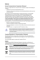
Notices Federal Communications Commission Statement This device complies with Part 15 of the FCC Rules. Operation is subject to the following two conditions: • • This device may not cause harmful interference, and This device must accept any interference received including interference that may cause undesired operation. This equipment has been tested and found to comply with the limits for a Class B digital device, pursuant to Part 15 of the FCC Rules.
Safety information Electrical safety • • • • • • • To prevent electric shock hazard, disconnect the power cable from the electric outlet before relocating the system. When adding or removing devices to or from the system, ensure that the power cables for the devices are unplugged before the signal cables are connected. If possible, disconnect all power cables from the existing system before you add a device.
About this guide This user guide contains the information you need when installing and configuring the motherboard. How this guide is organized This guide contains the following parts: • Chapter 1: Product introduction • This chapter describes the features of the motherboard and the new technology it supports. Chapter 2: BIOS information This chapter tells how to change system settings through the BIOS Setup menus. Detailed descriptions of the BIOS parameters are also provided.
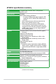
AT3N7A-I specifications summary CPU Chipset Front Side Bus Memory Graphics Expansion slot Storage Audio LAN USB Fan ASUS special features Integrated Dual-Core Intel® Atom™ 330 processor NVIDIA® ION™ 533 MHz Dual channel memory architecture - 2 x 240-pin DIMM sockets support maximum 4GB unbuffered non-ECC 800/667 MHz DDR2 memory modules * Refer to www.asus.com or this user manual for the Memory QVL (Qualified Vendors Lists).
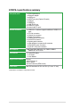
AT3N7A-I specifications summary Rear panel ports Internal connectors BIOS features Accessories Support DVD contents Form Factor 1 x PS/2 Keyboard port 1 x Bluetooth adapter 1 x eSATA port 2 x S/PDIF out ports (Optical & Coaxial) 1 x VGA port 1 x HDMI port 1 x LAN (RJ-45) port 8 x USB 2.0/1.1 ports 8-channel audio I/O ports 1 x USB 2.0/1.1 connector supports additional 2 USB 2.0/1.
Chapter 1 Product introduction Thank you for buying an ASUS® AT3N7A-I motherboard! Before you start installing the motherboard, and hardware devices on it, check the items in your motherboard package. Refer to page ix for the list of accessories. If any of the items is damaged or missing, contact your retailer. 1.1 Before you proceed Take note of the following precautions before you install motherboard components or change any motherboard settings.
1.2 Motherboard overview 1.2.1 Motherboard layout Ensure that you install the motherboard into the chassis in the correct orientation. The edge with external ports goes to the rear part of the chassis. Place this side towards the rear of the chassis. Place four screws into the holes indicated by circles to secure the motherboard to the chassis. DO NOT overtighten the screws! Doing so can damage the motherboard. 1.2.
1.3 Central Processing Unit (CPU) The motherboard comes with an onboard Dual-Core Intel® Atom™ 330 processor and a specially designed CPU heatsink and fan. Ensure that the CPU fan cable is connected to the onboard CPU_Fan connector. 1.4 System memory 1.4.1 Overview The motherboard comes with two Double Data Rate 2 (DDR2) Dual Inline Memory Modules (DIMM) sockets.
1.4.2 Memory configurations You may install 512MB, 1GB, and 2GB unbuffered non‑ECC DDR2 DIMMs into the DIMM sockets. • You may install varying memory sizes in Channel A and Channel B. The system maps the total size of the lower-sized channel for the dual-channel configuration. Any excess memory from the higher-sized channel is then mapped for the single-channel operation. • Always install DIMMs with the same CAS latency.
DDR2-800 MHz capability Vendor Part No. 2048MB(Kit of 2) 1024MB 2048MB 4096MB(Kit of 2) 512MB 1024MB 2048MB 1024MB 1024MB 1024MB 4096MB(Kit of 2) 4096MB(Kit of 2) 2048MB(kit of 2) 2048MB 4096MB(kit of 2) 4096MB(kit of 2) A-Data A-Data A-Data A-Data Apacer Apacer Apacer Corsair Corsair Corsair Corsair Corsair Crucial Crucial Crucial Crucial AD2800E001G0U SS M2GVD6G314170Q1E58 DS AD2800002GMU DS AD2800E002GOU DS 78.91G9I.9K5 SS 78.01GA0.9L5 SS 78.A1GA0.
DDR2-800 MHz capability Chip NO.
1.5 Expansion slot In the future, you may need to install expansion cards. The following sub‑sections describe the slot and the expansion cards that it supports. Unplug the power cord before adding or removing expansion cards. Failure to do so may cause you physical injury and damage motherboard components. 1.5.1 Installing an expansion card To install an expansion card: 1.
1.6 1. Jumpers Clear RTC RAM (3-pin CLRTC) This jumper allows you to clear the Real Time Clock (RTC) RAM in CMOS. You can clear the CMOS memory of date, time, and system setup parameters by erasing the CMOS RTC RAM data. The onboard button cell battery powers the RAM data in CMOS, which include system setup information such as system passwords. To erase the RTC RAM: 1. Turn OFF the computer and unplug the power cord. 2. Move the jumper cap from pins 1-2 (default) to pins 2-3.
1.7 Connectors 1.7.1 Rear panel connectors 1. PS/2 Keyboard port (purple). This port is for a PS/2 keyboard. 2. Video Graphics Adapter (VGA) port. This 15-pin port is for a VGA monitor or other VGA-compatible devices. 3. USB 2.0 ports 5 and 6. These two 4-pin Universal Serial Bus (USB) ports are available for connecting USB 2.0 devices. 4. Onboard Bluetooth module. This onboard Bluetooth module allows wireless connection and data transfer between your system and other Bluetooth devices.
9. Line Out port (lime). This port connects to a headphone or a speaker. In the 4, 6 and 8-channel configurations, the function of this port becomes Front Speaker Out. 10. Microphone port (pink). This port connects to a microphone. 11. Side Speaker Out port (gray). This port connects to the side speakers in the 8-channel audio configuration. Refer to the audio configuration table below for the function of the audio ports in the 2, 4, 6, or 8-channel configuration.
1.7.2 1. Internal connectors ATX power connectors (24-pin EATXPWR, 4-pin ATX12V) These connectors are for ATX power supply plugs. The power supply plugs are designed to fit these connectors in only one orientation. Find the proper orientation and push down firmly until the connectors completely fit. • We recommend that you use an ATX 12V Specification 2.0‑compliant power supply unit (PSU) with a minimum of 400W power rating. This PSU type has 24-pin and 4-pin power plugs.
2. Serial ATA connectors (7-pin SATA1, SATA2, SATA3) These connectors are for the Serial ATA signal cables for Serial ATA 3Gb/s hard disk drives and optical disk drives. The Serial ATA 3Gb/s is backward compatible with the Serial ATA 1.5Gb/s specification. The data transfer rate of the Serial ATA 3Gb/s is faster than the standard parallel ATA (133 MB/s). • Install the Windows® XP Service Pack 1 or later versions before using Serial ATA.
3. USB connector (10-1 pin USB910) This connector is for a USB 2.0 port. Connect the USB module cable to this connector, then install the module to a slot opening at the back of the system chassis. This USB connector complys with USB 2.0 specification that supports up to 480 Mbps connection speed. Never connect a 1394 cable to the USB connector. Doing so will damage the motherboard! The USB module cable is purchased separately. 4.
5. CPU, power, and chassis fan connectors (3-pin CPU_FAN, 3-pin PWR_FAN, 3-pin CHA_FAN) The fan connectors support cooling fans of 350 mA~2000 mA (24 W max.) or a total of 1 A~3.48 A (41.76 W max.) at +12V. Connect the fan cables to the fan connectors on the motherboard, ensuring that the black wire of each cable matches the ground pin of the connector. Do not forget to connect the fan cables to the fan connectors. Insufficient air flow inside the system may damage the motherboard components.
7. • • • • System panel connector (10-1 pin F_PANEL) This connector supports several chassis-mounted functions. System power LED (2-pin PLED) This 2-pin connector is for the system power LED. Connect the chassis power LED cable to this connector. The system power LED lights up when you turn on the system power, and blinks when the system is in sleep mode. Hard disk drive activity LED (2-pin HD_LED) This 2-pin connector is for the HDD Activity LED.
1.8 Software support 1.8.1 Installing an operating system This motherboard supports Windows® XP/Vista Operating Systems (OS). Always install the latest OS version and corresponding updates to maximize the features of your hardware. • Motherboard settings and hardware options vary. Refer to your OS documentation for detailed information.
Chapter 2 BIOS information 2.1 Managing and updating your BIOS Save a copy of the original motherboard BIOS file to a USB flash disk in case you need to restore the BIOS in the future. Copy the original motherboard BIOS using the ASUS Update utility. 2.1.1 ASUS Update utility The ASUS Update is a utility that allows you to manage, save, and update the motherboard BIOS in Windows® environment. • ASUS Update requires an Internet connection either through a network or an Internet Service Provider (ISP).
The ASUS Update utility is capable of updating itself through the Internet. Always update the utility to avail all its features. Updating from a BIOS file 3. a. Select Update BIOS from a file, then click Next. b. Locate the BIOS file from the Open window, then click Open. Follow the onscreen instructions to complete the updating process. 2.1.2 ASUS EZ Flash 2 The ASUS EZ Flash 2 feature allows you to update the BIOS without using an OS‑based utility.
• This function supports USB flash disks with FAT 32/16 format and single partition only. • DO NOT shut down or reset the system while updating the BIOS to prevent system boot failure! 2.1.3 ASUS CrashFree BIOS The ASUS CrashFree BIOS is an auto recovery tool that allows you to restore the BIOS file when it fails or gets corrupted during the updating process. You can restore a corrupted BIOS file using the motherboard support DVD or a removable device that contains the updated BIOS file.
2.2 BIOS setup program Use the BIOS Setup program to update the BIOS or configure its parameters. The BIOS screens include navigation keys and brief online help to guide you in using the BIOS Setup program. Entering BIOS Setup at startup To enter BIOS Setup at startup: • Press during the Power-On Self Test (POST). If you do not press , POST continues with its routines. Entering BIOS Setup after POST To enter BIOS Setup after POST: • Press ++ simultaneously.
2.3.1 System Time [xx:xx:xx] 2.3.2 System Date [Day xx/xx/xxxx] 2.3.3 SATA 1~3, ESATA Allows you to set the system time. Allows you to set the system date. While entering Setup, the BIOS automatically detects the presence of SATA devices. There is a separate sub-menu for each SATA device. Select a device item then press to display the SATA device information.
2.3.4 Storage Configuration The items in this menu allow you to set or change the configurations for the SATA devices installed in the system. Select an item then press if you want to configure the item. OnChip S-ATA Controller [Enabled] Enables or disables the OnChip SATA controller. Configuration options: [Disabled] [Enabled] SATA Mode Select [SATA Mode] This item appears only when you set the OnChip SATA Controller item to [Enabled]. Allows you to set the OnChip SATA mode.
2.4.1 CPU Configuration The items in this menu show the CPU-related information that the BIOS automatically detects. Max CPUID Value Limit [Disabled] Allows you to determine whether to limit CPUID maximum value. Set this item to [Disabled] for Windows XP operating system; set this item to [Enabled] for legacy operating system such as Windows NT4.0.
CPU Vcore Over Voltage Control [Auto] Sets the CPU Vcore over voltage. Configuration options: [Auto] [+100mV] Memory Timings [Auto] Sets the memory timings. Configuration options: [Auto] [Manual] The following items appear only when you set the Memory Timings item to [Manual].
2.4.4 Onboard Devices Configuration AZALIA AUDIO [Auto] Allows you to set the Azalia audio. Configuration options: [Auto] [Disabled] Front Panel Select [HD Audio] Allows you to select the front panel type. If High Definition Audio Front Panel used, please set HD Audio mode. Configuration options: [AC97] [HD Audio] Onboard Gigabit LAN [Enabled] Allows you to enable or disable the onboard LAN controller.
The following items may only appear when a USB storage device is plugged. USB Mass Storage Device Configuration USB Mass Storage Reset Delay [20 Sec] Allows you to set the maximum time that the BIOS waits for the USB storage device to initialize. Configuration options: [10 Sec] [20 Sec] [30 Sec] [40 Sec] Emulation Type [Auto] Allows you to select the emulation type. Configuration options: [Auto] [Floppy] [Forced FDD] [Hard Disk] [CDROM] 2.4.
2.5.2 ACPI 2.0 Support [Disabled] 2.5.3 ACPI APIC Support [Enabled] 2.5.4 APM Configuration Allows you to add more tables for Advanced Configuration and Power Interface (ACPI) 2.0 specifications. Configuration options: [Disabled] [Enabled] Allows you to enable or disable the Advanced Configuration and Power Interface (ACPI) support in the Application-Specific Integrated Circuit (ASIC). When set to Enabled, the ACPI APIC table pointer is included in the RSDT pointer list.
2.6 Boot menu The Boot menu items allow you to change the system boot options. Select an item then press to display the sub-menu. Main Advanced Power BIOS SETUP UTILITY Boot Tools Exit Boot Settings Boot Device Priority Boot Settings Configuration Security 2.6.1 Specifies the Boot Device Priority sequence. A virtual floppy disk drive (Floppy Drive B:) may appear when you set the CD-ROM drive as the first boot device.
Wait For ‘F1’ If Error [Enabled] When set to Enabled, the system waits for the F1 key to be pressed when error occurs. Configuration options: [Disabled] [Enabled] Hit ‘DEL’ Message Display [Enabled] When set to [Enabled], the system displays the message Press DEL to run Setup during POST. Configuration options: [Disabled] [Enabled] 2.6.3 Security The Security menu items allow you to change the system security settings. Select an item then press to display the configuration options.
Change User Password Select this item to set or change the user password. The User Password item on top of the screen shows the default Not Installed. After you set a password, this item shows Installed. To set a User Password: 1. Select the Change User Password item and press . 2. In the password box, key in a password containing up to six letters or numbers, or both, then press . 3. Confirm the password when prompted.
2.7.2 Express Gate [Auto] Allows you to enable or disable the ASUS Express Gate feature. ASUS Express Gate is a unique instant-on environment that provides quick access to the Internet and Skype. Configuration options: [Enabled] [Disabled] [Auto] Enter OS Timer [10 Seconds] Sets countdown duration that the system waits at the Express Gate’s first screen before starting Windows or other installed OS. Choose [Prompt User] to stay at the first screen of Express Gate for user action.