
Pin Definition
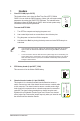

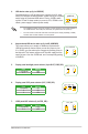
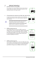

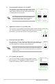

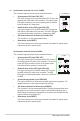
Table Of Contents

1-6
Motherboard Pin Denition
3 Internal Connectors
1. Serial port connector (10-1 pin COM)
This connector is for a serial (COM) port. Connect the serial port
module cable to this connector, then install the module to a slot
opening at the back of the system chassis.
2. CPU and chassis fan connectors (4-pin CPU_FAN, 4-pin CHA_FAN)
Connect the fan cable to the fan connector on the motherboard,
ensuring that the black wire of the cable matches the ground pin
of the connector
Do not forget to connect the fan cables to the fan connectors.
Insufcientairowinsidethesystemmaydamagethe
motherboard components. These are not jumpers! Do not place
jumper caps on the fan connectors! The CPU_FAN connector
supports a CPU fan of maximum 1A (12 W) fan power.
PIN 1
COM
DCD
TXD
GND
RTS
RI
RXD
DTR
DSR
CTS
CPU_FAN
CPU FAN PWM
CPU FAN IN
CPU FAN PWR
GND
+5V
CHA FAN IN
CHA FAN PWR
GND
CHA_FAN
C
3. USB 3.0 connector (20-1 pin)
This connector allows you to connect a USB 3.0 module for
additional USB 3.0 front or rear panel ports. With an installed USB
3.0module,youcanenjoyallthebenetsofUSB3.0including
faster data transfer speeds of up to 5 Gbps, faster charging time
forUSB-chargeabledevices,optimizedpowerefciency,and
backward compatibility with USB 2.0.
4. USB 2.0 connector (10-1 pin)
This connector is for USB 2.0 ports. Connect the USB module cable
to this connector, then install the module to a slot opening at the back
of the system chassis. This USB connector complies with USB 2.0
specicationsandsupportsupto480Mbpsconnectionspeed.
USB3
PIN 1
USB3+5V
IntA_P1_SSRX-
IntA_P1_SSRX+
GND
IntA_P1_SSTX-
IntA_P1_SSTX+
GND
IntA_P1_D-
IntA_P1_D+
GND
USB3+5V
IntA_P2_SSRX-
IntA_P2_SSRX+
GND
IntA_P2_SSTX-
IntA_P2_SSTX+
GND
IntA_P2_D-
IntA_P2_D+
USB
PIN 1
USB+5V
USB_P11-
USB_P11+
GND
NC
USB+5V
USB_P12-
USB_P12+
GND