
Pin Definition
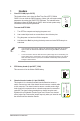

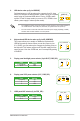
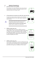

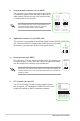

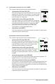
Table Of Contents

Motherboard Pin Denition
1-7
5. Single USB 2.0 connector (5-1 pin)
This connector is for a USB 2.0 port. Connect the USB module cable
to this connector, then install the module to a slot opening at the back
of the system chassis. This USB connector complies with USB 2.0
specicationsandsupportsupto480Mbpsconnectionspeed.
PIN 1
USBE5
+5V DC
Data(negative)
Data(positive)
Groud
•
Forafullyconguredsystem,werecommendthatyouuseapowersupplyunit
(PSU)thatcomplieswithATX12VSpecication2.0(orlaterversion)andprovidesa
minimum power of 350 W.
•
DONOTforgettoconnectthe4-pin/8-pinATX+12Vpowerplug.Otherwise,the
system will not boot up.
• WerecommendthatyouuseaPSUwithhigherpoweroutputwhenconguringa
system with more power-consuming devices or when you intend to install additional
devices. The system may become unstable or may not boot up if the power is
inadequate.
•
Ifyouareuncertainabouttheminimumpowersupplyrequirementforyoursystem,
refer to the Recommended Power Supply Wattage Calculator at http://support.asus.
com/PowerSupplyCalculator/PSCalculator.aspx?SLanguage=en-us for details.
6. ATX power connectors (24-pin EATXPWR, 8-pin EATX12V, 4-pin EATX12V)
TheseconnectorsareforATXpowersupply
plugs.Thepowersupplyplugsaredesignedtot
these connectors in only one orientation. Find the
properorientationandpushdownrmlyuntilthe
connectorscompletelyt.
EATX12V
+12V DC
+12V DC
+12V DC
+12V DC
GND
GND
GND
GND
EATXPWR
PIN 1
PIN 1
GND
+5 Volts
+5 Volts
+5 Volts
-5 Volts
GND
GND
GND
PSON#
GND
-12 Volts
+3 Volts
+3 Volts
+12 Volts
+12 Volts
+5V Standby
Power OK
GND
+5 Volts
GND
+5 Volts
GND
+3 Volts
+3 Volts
ATX12V
PIN 1
+12V DC
+12V DC
GND
GND
7. Speaker connector (4-pin SPEAKER)
The 4-pin connector is for the chassis-mounted system warning speaker.
The speaker allows you hear system beeps and warnings.
+5V
GND
GND
Speaker Out
SPEAKER
PIN 1