
Pin Definition
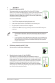

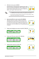
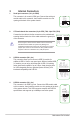

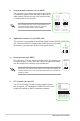

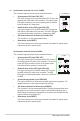
Table Of Contents

1-8
Motherboard Pin Denition
8. Front panel audio connector (10-1 pin AAFP)
This connector is for a chassis-mounted front panel audio
I/O module that supports either HD Audio or legacy AC`97
audio standard. Connect one end of the front panel audio
I/O module cable to this connector.
AAFP
PIN 1
AGND
NC
SENSE1_RETUR
SENSE2_RETUR
PORT1 L
PORT1 R
PORT2 R
SENSE_SEND
PORT2 L
HD-audio-compliant
pin definition
PIN 1
AGND
NC
NC
NC
MIC2
MICPWR
Line out_R
NC
Line out_L
Legacy AC’97
compliant definition
Werecommendthatyouconnectahigh-denitionfront
panel audio module to this connector to avail of the
motherboard’shigh-denitionaudiocapability.
9. Digital audio connector (4-1 pin SPDIF_OUT)
This connector is for an additional Sony/Philips Digital Interface (S/PDIF)
port. Connect the S/PDIF Out module cable to this connector, then install
the module to a slot opening at the back of the system chassis.
SPDIF_OUT
+5V
SPDIFOUT
GND
10. Direct connector (2-pin DRCT)
This connector is for the chassis-mounted button that supports the
DirectKey function. Connect the button cable that supports DirectKey,
from the chassis to this connector on the motherboard.
Ensure that your chassis comes with the button cable that supports the
DirectKey feature. Refer to the technical documentation that came with the
chassis for details.
PIN 1
DRCT
DRCT
GND
11. LPT connector (26-1 pin LPT)
The LPT (Line Printing Terminal) connector supports devices
suchasaprinter.LPTstandardizesasIEEE1284,whichisthe
parallel port interface on IBM PC-compatible computers.
PIN 1
O_LPT_XSTB#_R
O_LPT_XPD0_R
O_LPT_XPD1_R
O_LPT_XPD2_R
O_LPT_XPD3_R
O_LPT_XPD4_R
O_LPT_XPD5_R
O_LPT_XPD6_R
O_LPT_XPD7_R
O_LPT_ACK#_R
O_LPT_BUSY_R
O_LPT_PE_R
O_LPT_SLCT_R
O_LPT_XAFD#_R
O_LPT_ERROR#_R
O_LPT_XINIT#_R
O_LPT_XSLIN#_R
GND
GND
GND
GND
GND
GND
GND
GND