使用手冊 Motherboard B150I PRO GAMING/ AURA SERIES
T11158 第一版 2016 年 1 月發行 版權說明 ©ASUSTeK Computer Inc. All rights reserved.
Offer to Provide Source Code of Certain Software This product may contain copyrighted software that is licensed under the General Public License (“GPL”) and under the Lesser General Public License Version (“LGPL”). The GPL and LGPL licensed code in this product is distributed without any warranty. Copies of these licenses are included in this product.
目錄內容 安全性須知..........................................................................................................................................v 關於這本使用手冊.......................................................................................................................... vi 包裝內容物..................................................................................................................................... viii B150I PRO GAMING/AURA SERIES 規格列表...................................................
安全性須知 電氣方面的安全性 • 為避免可能的電擊造成嚴重損害,在搬動電腦主機之前,請先將電腦電源線暫時 從電源插槽中拔掉。 • 當您要加入硬體裝置到系統中或者要移除系統中的硬體裝置時,請務必先連接該 裝置的排線,然後再連接電源線。可能的話,在安裝硬體裝置之前先拔掉電腦的 電源供應器電源線。 • 當您要從主機板連接或拔除任何的排線之前,請確定所有的電源線已事先拔掉。 • 在使用介面卡或擴充卡之前,我們建議您可以先尋求專業人士的協助。這些裝置 有可能會干擾接地的迴路。 • 請確定電源供應器的電壓設定已調整到本國/本區域所使用的電壓標準值。若您不 確定您所屬區域的供應電壓值為何,那麼請就近詢問當地的電力公司人員。 • 如果電源供應器已損壞,請不要嘗試自行修復。請將之交給專業技術服務人員或 經銷處理。 操作方面的安全性 • 在您安裝主機板以及加入硬體裝置之前,請務必詳加閱讀本手冊所提供的相關資 訊。 • 在使用產品之前,請確定所有的排線、電源線都已正確地連接好。若您發現有任 何重大的瑕疵,請儘速連絡您的經銷商。 • 為避免發生電氣短路情形,請務必將所有沒用到的螺絲、迴紋針及其他零件收 好,不要遺留在主機板上或電腦
關於這本使用手冊 產品使用手冊包含了所有當您在安裝華碩 B150I PRO GAMING/AURA SERIES 主機 板時所需用到的資訊。 使用手冊的編排方式 使用手冊是由下面幾個章節所組成: • 第一章:產品介紹 您可以在本章節中發現諸多華碩所賦予本主機板的優異特色。利用簡潔易懂的 說明讓您能很快地掌握本主機板的各項特性,當然,在本章節中我們也會提及所 有能夠應用在本主機板的新產品技術。詳細內容有:主機板上的內建開關、跳線 選擇區以及連接埠。 • 第二章:BIOS 資訊 本章節描述如何使用 BIOS 設定程式中的每一個選單項目來更改系統的組態設 定。此外也會詳加介紹 BIOS 各項設定值的使用時機與參數設定。 提示符號 為了能夠確保您正確地完成主機板設定,請務必注意下面這些會在本手冊中出現 的標示符號所代表的特殊含意。 警告:提醒您在進行某一項工作時要注意您本身的安全。 小心:提醒您在進行某一項工作時要注意勿傷害到電腦主機板元件。 重要: 此符號表示您必須要遵照手冊所描述之方式完成一項或多項軟硬體的安 裝或設定。 注意:提供有助於完成某項工作的訣竅與其他額外的資訊。 vi
哪裡可以找到更多的產品資訊 您可以經由下面所提供的兩個管道來獲得您所使用的華碩產品資訊以及軟硬體的 更新資訊等。 1. 華碩網站 您可以到 http://www.asus.com/tw/ 華碩電腦全球資訊網站取得所有關於華碩軟硬體 產品的各項資訊。 2. 其他檔案 在您的產品包裝盒中除了本手冊所列舉的標準配件之外,也有可能會夾帶有其他 的檔案,譬如經銷商所附的產品保證單據等。 服務據點查詢 您可以至 http://www.asus.
包裝內容物 在您拿到本主機板包裝盒之後,請馬上檢查下面所列出的各項標準配件是否齊全。 主機板 華碩 B150I PRO GAMING/AURA SERIES 主機板 排線 2 x Serial ATA 6.0 Gb/s 排線 配件 1 1 1 1 1 1 1 公用程式光碟 驅動程式與公用程式光碟 相關文件 使用手冊 x x x x x x x I/O 擋板 PRO GAMING 排線貼紙 M.2 螺絲包 M.2 2242 安裝工具 束線帶組 CPU 安裝工具 Wi-Fi 2T2R 天線(視型號而定) 若以上列出的任何一項配件有損毀或是短缺的情形,請盡速與您的經銷 商聯絡。 B150I PRO GAMING/AURA SERIES 規格列表 中央處理器 支援 LGA1151 插槽 Intel® 第六代 Core™ i7/i5/i3/Pentium®/ Celeron® 處理器 支援 14nm 處理器 支援 Intel® Turbo Boost 2.0 技術* * 是否支援 Intel® Turbo Boost 技術 2.
B150I PRO GAMING/AURA SERIES 規格列表 儲存媒體連接槽 Intel® B150 Express 晶片組 - 4 x SATA 6.0 Gb/s 連接埠 - 1 x 具備 M Key 的 M.2 Socket 3,支援類型 2242/2260/2280 的儲存裝置(PCIe x4 通道與 SATA 模式)* 網路功能 Intel® Gigabit LAN 網路控制器 Anti-surge LANGuard GameFirst technology * 無線網路(視型號而定) 由 M.2 2242 安裝工具支援 Wi-Fi 802.11 a/b/g/n/ac,支援雙頻 2.4/5 GHz(MU_MIMO 支援) 藍牙 v4.
B150I PRO GAMING/AURA SERIES 規格列表 後側面板裝置連接埠 1 1 1 1 1 1 2 2 2 8 內建 I/O 裝置連接埠 1 x 1 9-pin USB 3.0/2.0 擴充套件排線插槽,可擴充 2 組外接式 USB 3.0/2.0 連接埠 1 x USB 2.0/1.1 擴充套件排線插槽,可擴充 2 組外接式 USB 2.0/1.1 連接埠 1 x 系統面板連接插座 1 x 前面板音效連接排針(AAFP) 4 x SATA 6.0 Gb/s 裝置連接插座 1 x 具備 M Key 的 M.
產品介紹 1.1 主機板安裝前 1 在您動手更改主機板上的任何設定之前,請務必先作好以下所列出的各項預防措 施。 • 在處理主機板上的任何元件之前,請您先拔掉電腦的電源線。 • 為避免產生靜電,在拿取任何電腦元件時除了可以使用防靜電手環之 外,您也可以觸摸一個有接地線的物品或者金屬物品像電源供應器外 殼等。 • 在您安裝或移除任何元件之前,請確認 ATX 電源供應器的電源開關是 切換到關閉(OFF)的位置,而最安全的做法是先暫時拔出電源供應器 的電源線,等到安裝/移除工作完成後再將之接回。如此可避免因仍有 電力殘留在系統中而嚴重損及主機板、周邊裝置、元件等。 1.2 主機板概述 當您安裝主機板到電腦機殼內時,請確認主機板與機殼大小相適應。 請確認在安裝或移除主機板前先拔除電源線,否則可能導致主機板元器 件毀損與對使用者的人身傷害。 1.2.1 主機板的擺放方向 當您安裝主機板到電腦主機機殼內時,務必確認安裝的方向是否正確。主機板的 外接插頭的方向應是朝向主機機殼的後方面板,而且您也會發現主機機殼後方面板會 有相對應的預留孔位。 1.2.
此面朝向電腦主 機的後方面板 1.2.3 主機板結構圖 * 僅某些型號搭載 Wi-Fi 802.11 a/b/g/n/ac 藍牙 V4.
1.2.4 主機板元件說明 連接插槽/跳線選擇區/插槽/LED 1. ATX power connectors (24-pin EATXPWR, 8-pin EATX12V) 頁數 2. Intel® LGA1151 CPU socket CPU, water pump, and chassis fan connectors (4-pin CPU_FAN; 4-pin W_ PUMP; 4-pin CHA_FAN) DDR4 DIMM slots 1-4 System panel connector (10-1 pin F_PANEL) System speaker connector (4-pin SPEAKER) 1-25 1-25 Intel® B150 Serial ATA 6.0 Gb/s connector (7-pin SATA6G_1~6) Clear RTC RAM (2-pin CLRTC) USB 3.
1.
1.3.
CPU正面 1-6 第一章:產品介紹
1.3.
請按照以下的步驟卸除散熱器和風扇: 1.4 系統記憶體 1.4.
1.4.2 記憶體設定 您可以任意選擇使用 2GB、4GB、8GB 與 16GB unbuffered non‑ECC DDR4 記憶體 模組至本主機板的 DIMM 插槽上。 記憶體建議設定: • 您可以在通道 A 與通道 B 安裝不同容量的記憶體模組,在雙通道設定 中,系統會偵測較低容量通道的記憶體容量。任何在較高容量通道的其 他記憶體容量,會被偵測為單通道模式執行。 • 由於 Windows® 32-bit 作業系統記憶體位址的限制,當您安裝 4GB 或更 大記憶體時,實際可使用的記憶體將為 3GB 或更小。為了更加有效地使 用記憶體空間,我們建議您做以下操作: - 若要安裝 Windows® 32 位元作業系統,請安裝最多 3GB 總記憶體。 - 若要安裝 4GB 或更多總記憶體,請安裝 Windows® 64 位元作業系統。 - 若需要更詳細的資料,請造訪 Microsoft® 網站 http://support.microsoft. com/kb/929605/zh-tw。 • 依據 Intel® CPU 規格,建議您安裝電壓低於 1.
B150I PRO GAMING/AURA SERIES 主機板合格供應商列表(QVL) DDR4 2133 MHz 1-10 支援記憶體插槽 (選購) 1 2 供應商 型號 容量 SS/ DS 晶片廠商 晶片型號 時脈 電壓 ADATA ADATA Apacer Apacer AVEXIR CENTURY MICRO INC CENTURY MICRO INC AD4U2133W4G15-B AD4U2133W8G15 78.B1GM3.AF00B 78.C1GM3.AF10B AVD4U21331504G-4M 4GB 8GB 4GB 8GB 4GB SS DS SS DS SS SK Hynix SK Hynix SK Hynix SK Hynix AVEXIR H5AN4G8NMFRTFC H5AN4G8NMFRTFC H5AN4G8NMFRTFC H5AN4G8NMFRTFC 512X8DDR4 15-15-15-36 15-15-15-36 15-15-15-36 15-15-15-36 15-15-15-35 1.2 1.2 1.2 1.
DDR4 2133 MHz(續上頁表格) 支援記憶體插槽 (選購) 1 2 • SS/ 晶片廠商 DS 晶片型號 時脈 電壓 SS - - 15-15-15-36 1.2 DS SK Hynix H5AN4GBNMFRTFC 15-15-15-36 1.2 • PUD42133C158GNJK M378A1G43DB0-CPB 4GB 16GB (2x 8GB) 8GB 8GB DS DS Samsung K4A4G085WD 15-15-15-36 15-15-15-36 1.
1.4.
1.5 擴充插槽 考慮到未來會擴充系統機能的可能性,本主機板提供了擴充插槽,在接下來的次 章節中,將會描述主機板上這些擴充插槽的相關資訊。 安裝 / 移除任何擴充卡之前,請暫時先將電腦的電源線拔出。如此可免除 因電氣殘留於電腦中而發生的意外狀況。 1.5.1 安裝擴充卡 請依照下列步驟安裝擴充卡: 1. 在安裝擴充卡之前,請先詳讀該擴充卡的使用說明,並且要針對該卡作必要的硬 體設定變更。 2. 鬆開電腦主機的機殼蓋並將之取下(如果您的主機板已經放置在主機內)。 3. 找到一個您想要插入新擴充卡的空置插槽,並以十字螺絲起子鬆開該插槽位於主 機背板的金屬擋板的螺絲,最後將金屬擋板移出。 4. 將擴充卡上的金手指對齊主機板上的擴充槽,接著慢慢地插入槽中,並以目視的 方法確認擴充卡上的金手指已完全沒入擴充槽中。 5. 再用剛才鬆開的螺絲將擴充卡固定在機殼內。 6. 將電腦主機的機殼蓋裝回鎖好。 1.5.2 設定擴充卡 在安裝好擴充卡之後,接著還須藉由軟體設定來調整該擴充卡的相關設定。 1.
1.5.3 PCI Express 3.0 x16 介面卡擴充插槽 本主機板配備 PCI Express 3.0 x 16 插槽,可支援 PCI Express 3.
1.6 1. 跳線選擇區 CMOS 組態資料清除(2-pin CLRTC) 本跳線可讓您清除 CMOS 的組態資料。您可以透過刪除 CMOS 組態資料,清 除 CMOS 中的日期、時間與系統設定參數記憶。CMOS 組態資料是由主機板內 建的鋰電池供電,數據包括系統設定訊息,像是系統密碼等。 想要清除這些資料,可以依照下列步驟進行: 1. 關閉電腦電源,拔掉電源線; 2. 用一個金屬物體,如螺絲起子,將 CLRTC 跳線帽的兩個針腳短路; 3. 插上電源線,開啟電腦電源; 4. 當開機步驟正在進行時按著鍵盤上的 <Del> 鍵進入 BIOS 程式畫面重新設 定 BIOS 資料。 • 如果上述方法無效,請移除主機板上的內建電池,再將跳線帽移除一 次來清除 CMOS 組態資料。在 CMOS 組態資料清除後,請將電池重 新裝回主機板。 • 如果您是因為超頻的緣故導致系統無法正常開機,您無須使用上述的 組態資料清除方式來排除問題。建議可以採用 C.P.
1.7 元件與周邊裝置的連接 1.7.1 後側面板連接埠 1. PS/2 鍵盤/滑鼠複合連接埠:本連接埠供 PS/2 滑鼠或鍵盤使用。 纖 S/PDIF 數位輸出連接埠:本連接埠讓您連接電腦以增強喇叭、耳機或與 2. 光 S/PDIF 相容的裝置音效。 3.
4. Wi-Fi 802.11 a/b/g/n/ac 藍牙 V4.
5. USB 2.0 連接埠:本 4-pin USB 連接埠供 USB 2.0/1.1 裝置使用。 VI-D 連接埠:本連接埠供任何與 DVI-D 相容的裝置使用。DVI-D 無法將訊號 6. D 轉換為 RGB 輸出至 CRT 顯示器,且與 DVI-I 不相容。 SB 3.0 Type C 連接埠:本連接埠供 USB 3.0 行動及周邊裝置使用。 7. U DMI 連接埠:本連接埠供 HDMI 排線使用,且支援 HDCP 標準的 HD DVD、. 8. H Blu-ray(藍光)與其他受保護的內容播放。 9. USB 3.0 連接埠:本 9-pin USB 連接埠供 USB 3.0 裝置使用 • USB 3.0 裝置僅可作為資料儲存裝置使用 • 強烈建議您將 USB 3.0 裝置連接到 USB 3.0 連接埠,以得到更快的 傳送速率與更好的效能。 • 由於Intel® 100 系列晶片組的設計,所有連接至 USB 2.0 與 USB 3.0 連接埠的 USB 裝置由 xHCI 控制器控制。有些較早的 USB 裝置必須 升級韌體後才可提高相容性。 10.
1.7.2 1. 內部連接埠 USB 2.0 連接插槽(10-1 pin USB78) 這些 USB 擴充套件排線插槽支援 USB 2.0 規格,將 USB 模組排線連接至任 一個插槽,然後將模組安裝到機殼後側面板中開放的插槽。這些 USB 插槽與 USB 2.0 規格相容,並支援傳輸速率最高達 480Mbps。 請勿將 1394 排線連接到 USB 插座上,這麼做可能會導致主機板的毀損。 USB 2.
2.
3. ATX 主機板電源插槽(24-pin EATXPWR、8-pin EATX12V) 這些電源插槽用來連接到一個 ATX 電源供應器。電源供應器所提供的連接插 頭已經過特別設計,只能以一個特定方向插入主機板上的電源插槽。找到正確的 插入方向後,僅需穩穩地將之套進插槽中即可。 • 建議您使用與 2.
4. 前面板音效連接排針(10-1 pin AAFP) 這組音效外接排針供您連接到前面板的音效排線,除了讓您可以輕鬆地通過 主機前面板來控制音效輸入/輸出等功能,並且支援 HD Audio 音效標準。將前面 板音效輸出/輸入模組的連接排線之一端連接到這個插槽上。 • 建議您將支援高傳真(high definition)音效的前面板音效模組連接到這 組排針,如此才能得到高傳真音效的功能。 • 若要將高傳真音效前面板模組安裝至本接針,請將 BIOS 程式中 Front Panel Type 項目設定為 [HD Audio],預設情況下本連接埠設定為 [HD Audio]。更多細節請參考 2.6.
5. USB 3.0 連接插槽(20-1 pin USB3_12) 這個插槽用來連接額外的 USB 3.0 連接埠模組,並與 USB 2.0 規格相容。若 是您的機殼提供有 USB 3.0 前面板連接排線,將該排線連接至本插槽,就可擁有 前面板 USB 3.0 解決方案,支援傳送速率最高達 5Gbps,可對 USB 充電裝置進 行快速充電並優化能效。 USB 3.0 模組需另行購買。 • 這些插槽是以 xHCI 規格為基礎,建議您在 Windows® 7 作業系統中 安裝相關的驅動程式來充分使用 USB 3.0 插槽。 ‧ 安裝的 USB 3.0 裝置將運行在 xHCI 狀態。 ‧ 這些 USB 3.0 連接埠在您使用 USB 3.0 Boost 功能時,支援Windows® 8/Windows® 8.1 作業系統中原生的 UASP 傳輸標準與 Turbo 模式。 6.
7. Intel® B150 Serial ATA 6.0Gb/s 裝置連接插座 (7-pin SATA6G_1~4) 這些插槽支援使用 Serial ATA 6.0Gb/s 排線連接 Serial ATA 6.
8.
1.8 1. 內建指示燈 電力指示燈(SB_PWR) 當主機板上內建的電力指示燈(SB_PWR)亮著時,表示當前系統是處於正常 運作、省電模式或者軟關機的狀態中,並非完全斷電。這個警示燈可用來提醒您 在安裝或移除任何的硬體裝置之前,都必須先移除電源,等待警示燈熄滅才可進 行。請參考下圖所示。 2.
3. SupremeFX 指示燈 SupremeFX 指示燈有以下兩種方式帶給您極致的燈光效果。此指示燈同時也. 作為主機板上音效元件區與其他元件的分界線。 燈光模式 呼吸模式 描述 指示燈間接閃爍。 恆亮模式 指示燈恆亮紅色。 您可以在 BIOS 或者 Ai Suite 3 的 LED 控制程式中關閉 SupremeFX 指示 燈,或更改其亮燈模式。若要在 BIOS 中更改,請至 Advanced > Onboard Devices Configuration > Audio LED Lighting 項目,詳情請參考 2.6.
1.9 軟體支援 1.9.1 安裝作業系統 本主機板完全適用於 Windows® 7(32bit/64bit)、Windows® 8.1(64bit)與 Windows® 10(64bit)作業系統。使用最新版本的作業系統並且不定時地更新,是讓硬體配備得 到最佳工作效率的有效方法。 由於主機板與周邊硬體裝置的選項設定繁多,本章僅就軟體的安裝程式供 您參考。您也可以參閱您使用的作業系統說明檔案以取得更詳盡的資訊。 1.9.2 驅動程式與公用程式光碟資訊 隨貨附贈的驅動程式與公用程式光碟包括了數個有用的軟體與公用程式,將它們 安裝到系統中可以強化主機板的機能。 驅動程式與公用程式光碟的內容若有更新,恕不另行通知。請造訪華碩網 站(http://www.asus.
2 BIOS 資訊 2.1 管理、更新您的 BIOS 程式 建議您先將主機板原始的 BIOS 程式備份到一片 USB 隨身碟中,以備您 往後需要再度安裝原始的 BIOS 程式。使用華碩線上更新程式來拷貝主機 板原始的 BIOS 程式。 2.1.
2.1.2 華碩 EZ Flash 3 華碩 EZ Flash 3 程式讓您能輕鬆的從網站上下載或更新 BIOS 程式,可以不必再 透過開機片的冗長程序或是再到作業系統模式下才可執行。 • 請載入BIOS程式的預設值以確保系統的相容性與穩定度。在 Exit 選單中 選擇 Load Optimized. Defaults 項目來復原 BIOS 預設值。更多細節請參 考 離開選單 一節的說明。 • 若要透過網際網路來更新 BIOS,請先檢查您的網際網路連線。 選 > 請依照以下步驟更新 BIOS 程式: 更 1. 進入 BIOS 設定程式的 Advanced Mode,選擇 Tool > ASUS EZ Flash 3 Utility, 接著請按下 鍵。 2.
2.1.3 華碩 CrashFree BIOS 3 程式 華碩 CrashFree BIOS 3 工具程式讓您在當 BIOS 程式與資料被病毒入侵或損毀時, 可以輕鬆地從驅動程式與公用程式光碟中,或是從含有最新或原始 BIOS 檔案的 USB 隨身碟中回復 BIOS 程式的資料。 •使用此程式前,請將行動儲存裝置中的 BIOS 檔案重新命名為:B5IPGA. CAP 或 B5IPGWA.CAP(Wi-Fi 型號適用)。 •從驅動程式與公用程式光碟中的 BIOS 可能不是最新版本,請造訪華碩 網站(http://www.asus.com/tw/)來下載最新的 BIOS 程式。 回復 BIOS 程式 請依照下列步驟回復 BIOS 程式: 1. 啟動系統。 2. 將儲存有 BIOS 檔案的驅動程式與公用程式光碟放入光碟機,或 USB 隨身碟插入 USB 連接埠。 3. 接著工具程式便會自動檢查裝置中是否存有 BIOS 檔案。當搜索到 BIOS 檔案 後,工具程式會開始讀取 BIOS 檔案並自動進入 EZ Flash 3 應用程式。 4.
在 DOS 環境中啟動系統 請依照以下步驟在 DOS 環境中啟動系統: 1. 將儲存有最新的 BIOS 檔案與 BIOS Updater 工具程式的 USB 隨身碟連接到電腦 的 USB 連接埠。 2. 啟動電腦然後按下 來啟動 BIOS Boot Device Select 選單。 3. 當 BIOS Boot Device Select 選單出現時,將驅動程式與公用程式光碟放入光碟 機,並選擇光碟機為啟動裝置。 Please select boot device: and to move selection ENTER to select boot device ESC to boot using defaults P2: ST3808110AS (76319MB) aigo miniking (250MB) UEFI: (FAT) ASUS DRW-2014L1T(4458MB) P1: ASUS DRW-2014L1T(4458MB) UEFI: (FAT) aigo miniking (250MB) Enter Setup 4.
2. 在 BIOS Updater 畫面中,按下 鍵從檔案欄位切換至磁碟欄位,然後選擇 D:。 ASUSTeK BIOS Updater for DOS V1.30 [2015/01/01] Current ROM BOARD: B150I PRO GAMING/AURA VER: 0204 (H :00 B :00) DATE: 09/24/2015 PATH: 磁碟 面板 Update ROM BOARD: Unknown VER: Unknown DATE: Unknown C:\ C: D: FORMAN~1 B5IPGA.CAP Note 16779264 [Enter] Select or Load [Up/Down/Home/End] Move 2015-09-24 [Tab] Switch [Esc] Exit 21:14:34 檔案 面板 [V] Drive Info 3. 按下 鍵從磁碟欄位切換至檔案欄位,接著用 鍵 來選擇 BIOS 檔案並按下 。 4.
2.2 BIOS 程式設定 BIOS 設定程式用於更新或設定 BIOS。BIOS 設定畫面中標示了操作功能鍵與簡明 的操作說明,幫助您進行系統設定。 在開機時進入 BIOS 設定,您可以依據以下步驟進行: • 在系統自我測試(POST)過程中按下 或 鍵。若不按下 或 鍵,自我測試會繼續進行。 在 POST 過程結束後再進入 BIOS 設定,您可以選擇以下任一步驟進行: • 按下 + + 鍵。 • 按下機殼上的 RESET 按鈕重新開機。 • 您也可以將電腦關閉然後再重新開機。請在嘗試了以上兩種方法失敗後再選擇這 一操作。 透過電源鍵、Reset 鍵或 + + 鍵強迫正在運作的系統重新 開機會毀損到您的資料或系統,我們建議您正確地關閉正在運作的系統。 • 本章節的 BIOS 程式畫面僅供參考,將可能與您所見到的畫面有所差異。 • 請至華碩網站(http://www.asus.
2.2.1 EZ 模式(EZ Mode) 預設情況下,當您進入 BIOS 設定程式後,EZ 模式(EZ Mode)畫面就會出現。 EZ 模式(EZ Mode)顯示基本系統資訊概要,並用來選擇顯示語言、系統效能模式 與啟動裝置順序。要進入進階模式(Advanced Mode),點選 Exit/Advanced Mode 按 鈕,接著選擇進階模式(Advanced Mode),或是按 鍵來進入進階 BIOS 設定。 進入 BIOS 設定程式的預設畫面可變更。更多細節請參考 2.
2.2.
功能表列 BIOS 設定程式最上方各選單功能說明如下: My Favorites 本項目用於保存經常使用的系統設定和配置資訊。 Main 本項目提供系統基本設定 Ai Tweaker 本項目用於變更超頻設定 Advanced 本項目提供系統進階功能設定 Monitor 本項目顯示系統溫度、電源狀態,並變更風扇設定 Boot 本項目提供系統開啟設定 Tool 本項目提供特殊功能設定 Exit 本項目提供離開 BIOS 設定程式與出廠預設值還原功能 選單項目 於功能表列選定選項時,被選擇的功能將會反白,即選擇 Main 選單所出現的項 目。 點選選單中的其他項目(例如:My Favories、Extreme Tweaker、Advanced、 Monitor、Boot 與 Exit)也會出現該項目不同的選項。 子選單 在選單畫面中,若功能選項前面有一個小三角形標記,代表此為子選單,您可利 用方向鍵來選擇,並按下 鍵來進入子選單。 語言 這個按鈕位在功能表列的上方,用來選擇 BIOS 程式介面顯示的語言。點選這個按 鈕來選擇您想要的 BIOS 畫面顯示語言。 我
快速鍵 這個按鈕位在功能表列的上方,包含有 BIOS 程式設定的導引方向鍵,使用箭頭按 鍵來選擇選單中的項目並變更設定。 搜尋 FAQ 將滑鼠移至此按鈕上方可顯示一個二維碼。用手機掃描此二維碼可連線至華碩 BIOS FAQ 網頁。您也可以直接掃描下方的二維碼。 捲軸 在選單畫面的右方若出現捲軸,即代表此頁選項超過可顯示的畫面,您可利用上/ 下方向鍵或是 PageUp/PageDown 鍵來切換畫面。 項目說明 在選單畫面的下方為目前所選擇的作用選項的功能說明,此說明會依選項的不同 而自動變更。使用 按鍵來抓取 BIOS 螢幕畫面,並儲存至攜帶式儲存裝置。 設定值 此區域顯示選單項目的設定值。這些項目中,有的功能選項僅為告知使用者目前 執行狀態,並無法更改,此類項目就會以淡灰色顯示。而可更改的項目,當您使用方 向鍵移動項目時,被選擇的項目以反白顯示。 設定值被選擇後以反白顯示。要改變設定值請選擇此項目,並按下 鍵以顯 示設定值列表。 上次修改的設定按鈕 按下此按鈕可檢視您在 BIOS 設定中上一次所做的修改項目。 2-10 第二章:BIOS 資訊
2.2.
手動設定風扇 從設定檔列表中選擇「Manual」來手動設定風扇運作的速度。 速度點 點選或輕觸以手動設定風扇 請按照以下步驟設定風扇: 2-12 1. 選擇想要設定的風扇並檢視該風扇現在的狀況。 2. 點選並拖曳速度點來調整風扇的運作速度。 3.
2.3 我的最愛(My Favorites) 在此選單中您可以輕鬆儲存並使用您偏好的 BIOS 項目設定。 我的最愛會記錄時常使用的系統設定及設定值。您可以依照自己偏好的 BIOS 項目 設定此選單。 在 My Favorites 中新增項目 依照以下步驟將經常使用的 BIOS 項目新增至我的最愛: 1. 在鍵盤按下 鍵或在 BIOS 程式畫面中點選 圖畫面。 2.
3. 從主選單欄選擇項目,然後點選子選單中想要儲存至我的最愛的選項,再點選或 輕觸 。 以下項目無法加入至我的最愛: • 使用者自訂項目,例如:語言、開機裝置順序。 2-14 4. 點選 Exit (ESC) 或按下 鍵來關閉樹狀圖視窗。 5.
2.4 主選單(Main) 當您進入 BIOS 設定程式的進階模式(Advanced Mode)時,首先出現的第一個畫 面即為主選單。主選單顯示系統資訊概要,用來設定系統日期、時間、語言與安全設 定。 2.4.1 Language [English] 用來選擇 BIOS 語言。 設定值有:[English] [한국어]。 2.4.2 [Español] [Русский] 安全性選單(Security) 本選單可讓您改變系統安全設定。 • 若您忘記設定的 BIOS 密碼,可以採用清除 CMOS 即時鐘(RTC)記憶 體器。請參閱 1.
系統管理員密碼(Administrator Password) 當您設定系統管理員密碼後,建議您先登入您的帳戶,以免 BIOS 設定程式中的某 些資訊無法檢視或變更設定。 設定系統管理員密碼 請按照以下步驟設定系統管理員密碼(Administrator Password): 1. 請選擇 Administrator Password 項目並按下 。 2. 由「Create New Password」視窗輸入欲設定的密碼,輸入完成按下 。 3. 請再一次輸入密碼以確認密碼正確。 變更系統管理員密碼 請按照以下步驟變更系統管理員密碼(Administrator Password): 1. 請選擇 Administrator Password 項目並按下 。 2. 由「Enter Current Password」視窗輸入密碼並按下 。 3. 由「Create New Password」視窗輸入新密碼,輸入完成按下 。 4.
2.5 Ai Tweaker 選單(Ai Tweaker) Ai Tweaker 選單項目可讓您設定超頻的相關選項。 在您設定此進階選單設定時,不正確的設定值將導致系統功能異常。 此部份中的設定值依您主機板上所安裝的 CPU 與記憶體模組型號而定。 將捲軸往下捲動來顯示其他項目。 2.5.
若您要設定 2-Core Ration Limit 數值,請勿將 1-Core Ration Limit 設定 為 [Auto] 。 3-Core Ratio Limit [Auto] 選擇 [Auto] 套用 CPU 預設的 Turbo 倍頻設定,或手動設定 3-Core Ration Limit。 設定值須高於或等於 4-Core Ratio Limit。 若您要設定 3-Core Ration Limit 數值,請勿將 1-Core Ration Limit 及 2-Core Ration Limit 設定為 [Auto] 。 4-Core Ratio Limit [Auto] 選擇 [Auto] 套用 CPU 預設的 Turbo 倍頻設定,或手動設定 4-Core Ration Limit。 設定值須高於或等於 3-Core Ratio Limit。 若您要設定 4-Core Ration Limit 數值,請勿將 1-Core Ration Limit、2-Core Ration Limit 及 3-Core Ration Limit 設定為 [Auto] 。 2.5.
2.5.5 GPU Boost [Keep Current Settings]] 啟動本項目以加速整合GPU,達到終極的繪圖效能。設定值有:[Keep Current Settings]] [Enabled]。 只有當您安裝支援的 CPU 時才能啟動本項目。 2.5.6 EPU Power Saving Mode [Disabled] 華碩 EPU 可以將處理器設定為最小能耗,啟動本功能來設定較低的 CPU VCCIN 與 Vcore 電壓,以達到最佳能源節省狀態。設定值有:[Disabled] [Enabled]。 2.5.7 CPU SVID Support [Auto] 關閉 SVID 支援以中斷處理器與外接電壓調節器的通訊。設定值有:[Auto] [Disabled] [Enabled]。 2.5.
CPU VRM Switching Frequency [Auto] 本項目會影響 VRM 暫態回應速度與元件溫度的產生。選擇 [Manual] 設定較高的 頻率可以獲得較快的暫態回應速度。設定值有:[Auto] [Manual]。 請勿將散熱系統移除,散熱環境需受到監控。 以下項目只有在 CPU VRM Switching Frequency 設定為 [Manual] 時才會 出現。 Fixed CPU VRM Frequency (KHz) [250] 本項目可讓您設定固定的 VRM 頻率。請使用 <+> 與 <-> 鍵調整數值。數 值以 50kHz 為間隔,更改的範圍由 250kHz 至 500kHz。 CPU Power Duty Control [T.Probe] 本項目用來調整每個元件相數的電流與散熱環境。 [T.
CPU Graphics Switching Frequency [Auto] 本項目會影響 GT 暫態回應速度與元件溫度的產生。選擇 [Manual] 設定較高的頻 率可以獲得較快的暫態回應速度。設定值有:[Auto] [Manual]。 請勿將散熱系統移除,散熱環境需受到監控。 以下項目只有在 CPU Graphics Switching Frequency 設定為 [Manual] 時 才會出現。 Fixed CPU Graphics Switching Frequency (KHz) [250] 本項目可讓您設定較高的頻率以獲得較快的暫態回應速度。請使用 <+> 與 <-> 鍵調整數值。數值以 50kHz 為間隔,更改的範圍由 250kHz 至 500kHz。 GT Power Duty Control [T.Probe] 本項目用來調整每個元件相數的電流與散熱環境。 [T.
Turbo Mode [Enabled] 本項目用來設定核心處理器在運作電源、現況與溫度規格限制下,以比基本運作 頻率更快的速度運作。設定值有:[Enabled] [Disabled]。 以下項目只有在 Turbo Mode 設定為 [Enabled] 時才會出現。 Turbo Mode 參數 Long Duration Package Power Limit [Auto] 本項目用來限制超出 TDP(散熱設計功耗)的 Turbo 倍頻持續時間,以達 到最佳效能。請使用 <+> 與 <-> 鍵調整數值。數值範圍從 1W 至 4095W。 Package Power Time Window [Auto] 本項目作為 Power Limit 1,用來維持超過 TDP(散熱設計功耗)的 Turbo 超頻的時間窗。請使用 <+> 與 <-> 鍵調整數值。數值變更的範圍從 1 至 127 秒。 Short Duration Package Power Limit [Auto] 本項目作為 Power Limit 2,當電力超過 Power Limit 1 時,為 CPU 提供 快速保護。請使用 <+> 與 <-> 鍵
2.5.15 Max. CPU Graphics Ratio [Auto] 本項目用來設定最大 CPU Graphics 倍頻。請使用 <+> 與 <-> 鍵調整數值,數值以 1 為間隔,更改的範圍由 1 至 60。 2.5.16 CPU Core/Cache Voltage [Auto] 本項目用來設定 CPU 核心的電壓總量。當核心頻率增加時請增加電壓總量。設定 值有:[Auto] [Manual Mode] [Offset Mode]。 以下項目只有在 CPU Core Voltage 設定為 [Manual Mode] 時才會出現。 CPU Core Voltage Override [Auto] 本項目用來設定 CPU 核心電壓覆寫。請使用 <+> 與 <-> 鍵調整數值,設定值以 0.005V 為間隔,更改的範圍從 0.600V 至 1.
2.6 進階選單(Advanced) 進階選單可讓您改變中央處理器與其他系統裝置的細部設定。 在您設定本進階選單的設定時,不正確的數值將導致系統毀損。 2.6.
CPU Power Management Configuration 本項目可讓您更改中央處理器電源管理的設定值。 Intel® SpeedStepTM [Auto] 本項目可以讓作業系統動態調整處理器電壓與核心頻率,藉以降低平均能 耗及熱量產生。設定值有:[Auto] [Disabled] [Enabled]。 Turbo Mode [Enabled] 本項目在低於操作電源、電流及溫度規格限制的情況下,允許處理器自動 以比標準頻率更快的速度運作。設定值有:[Enabled] [Disabled]。 CPU C-States [Auto] 本項目用來啟用或停用 CPU C states。設定值有:[Auto] [Disabled] [Enabled]。 以下項目只有在 CPU C states 設定為 [Enabled] 時才會出現。 Enhanced C states [Enabled] 本項目可以讓處理器在閒置時降低電力消耗。設定值有:[Enabled] [Disabled]。 CPU C3 Report [Enabled] 本項目可以讓您啟動或關閉 CPU C3 報告給作業系統。設定值有: [Enab
2.6.
iGPU Multi-Monitor [Disabled] 本項目用來啟動 iGPU 和獨立顯示卡的多重顯示功能。iGPU 共享系統記憶 體固定為 64MB。設定值有:[Disabled] [Enabled]。 RC6 (Render Standby) [Enabled] 本項目用來啟動 Render Standby 功能。設定值有:[Disabled] [Enabled]。 DVMT Pre-Allocated [32M] 本項目用來選擇內部顯示裝置使用的 DVMT 5.0 預分配(固定)顯示記憶體 容量。設定值有: [32M] [64M] [96M] [128M] [160M] [192M] [224M] [256M] [288M] [320M] [352M] [384M] [416M] [448M] [480M] [512M] [1024M]。 DMI/OPI Configuration 本項目用來設定 DMI(Direct Media Interface)以 PCI-E 2.
SATA Controller(s) [Enabled] 本項目可開啟或關閉內建的 SATA 裝置。設定值有:[Disabled] [Enabled]。 以下項目只有在 SATA Controller(s) 設定為 [Enabled] 時才會出現。 Aggressive LPM Support [Disabled] 本項目可支援 LPM (link power management) 以獲得更好的省電效果。關閉本項目 後,SATA 連接埠的熱抽換功能將被禁用。設定值有:[Disabled] [Enabled]。 SMART Self Test [On] 本項目用來開啟或關閉 POST 期間所有硬碟的 SMART 自我測試。設定值有:[On] [Off]。 M.2 [Enabled] 本項目用來開啟或關閉 M.
USB Single Port Control 本項目用來開啟或關閉 USB 連接埠。 USB3_1~4, USB7~10, USB3_C5 [Enabled] 本項目用來開啟或關閉單獨的 USB 連接埠。設定值有:[Disabled] [Enabled]。 更多細節請參考 1.2.3 主機板結構圖 一節的說明。 2.6.
Bluetooth Controller [Enabled] 本項目用來啟動或停用藍牙控制器。設定值有:[Disabled] [Enabled]。 僅某些型號支援本項目。 Intel LAN Controller [Enabled] [Enabled] [Disabled] 啟動 Intel 網路控制器。 關閉本功能。 Intel PXE Option ROM [Off] 本項目可讓您開啟或關閉 Intel 網路控制器的 PXE OptionRom。設定值有: [On] [Off]。 Charging USB devices in Power State S5 [Enabled] [Enabled] [Disabled] 2.6.
2.6.9 網路堆棧(Network Stack) Network Stack [Disabled] 本項目用來啟動或關閉 UEFI 網路堆棧(network stack)功能。設定值有:[Disabled] [Enabled]。 以下選項只有在 Network Stack 設定為 [Enabled] 時才會出現。 Ipv4/Ipv6 PXE Support [Enabled] 本項目用來開啟或關閉 Ipv4/Ipv6 PXE 啟動項支援。設定值有:[Disabled] [Enabled]。 2.6.
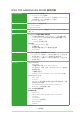
2.7 監控選單(Monitor) 監控選單可讓您查看系統溫度/電力狀況,並且對風扇做進階設定。 往下捲動可顯示其他 BIOS 項目。 2.7.1 CPU Temperature / Motherboard Temperature [xxxºC/xxxºF] 本系列主機板具備了中央處理器、主機板的溫度感測器,可自動檢測並顯示目前 主機板與處理器的溫度。若是您不想檢測這個項目,請選擇 [Ignore]。 2.7.2 CPU Fan Speed/ Water Pump Speed/ Chassis Fan 1 Speed [xxxx RPM]/ [N/A]/ [N/A] 為了避免系統因為過熱而造成損毀,本系列主機板備有風扇的轉速 RPM (Rotations Per Minute)監控,所有的風扇都設定了轉速安全範圍,一旦風扇轉速低 於安全範圍,華碩智慧型主機板就會發出警訊,通知使用者注意。如果風扇並未連接 至主機板,本項目會顯示 N/A。若是您不想檢測這個項目,請選擇 [Ignore]。 2.7.3 CPU Core Voltage/ 3.
CPU Q-Fan Control [Auto] [Auto] 偵測安裝的處理器風扇類型,並自動切換控制模式。 [Disabled] 關閉 CPU Q-Fan 控制功能。 [PWM Mode] 啟動 PWM 模式的處理器 Q-Fan 控制來使用 4-pin 處理器風扇。 [DC Mode] 啟動 DC 模式的處理器 Q-Fan 控制來使用 3-pin 處理器風扇。 CPU Fan Speed Lower Limit [200 RPM] 本項目可讓您手動設定處理器風扇的最低轉速限制。當處理器風扇轉速低於所設 定的最小值時,系統將發出嗶聲警告。設定值有:[Ignore] [100RPM] [200RPM] [300 RPM] [400 RPM] [500 RPM]。 CPU Fan Profile [Standard] 本項目用來設定處理器風扇適當的效能。 [Standard] 設定為 [Standard] 讓處理器風扇依據處理器的溫度自動調整。 [Silent] 設定為 [Silent] 將風扇速度調整到最低,並擁有最安靜的運作環境。 [Turbo] 設定為 [Turbo] 來獲得處
Chassis Fan 1 Q-Fan Control [DC Mode] [PWM mode] 啟動 PWM 模式的機殼 Q-Fan 控制來使用 4-pin 機殼風扇。 [DC mode] 啟動 DC 模式的機殼 Q-Fan 控制來使用 3-pin 機殼風扇。 [Disabled] 關閉此功能。 以下的項目只有在 Chassis Fan 1 Q-Fan Control 設為 [PWM Mode] 或 [DC Mode] 時才會出現。 Chassis Fan 1 Q-Fan Source [CPU] 依據所選擇的溫度來源,本項目可控制該風扇。設定值有:[CPU] [MotherBoard]。 Chassis Fan 1 Speed Low Limit [600 RPM] 本項目可讓您手動設定機殼風扇的最低轉速限制。當機殼風扇轉速低於所設定 的最小值時,系統將發出嗶聲警告。設定值有:[Ignore] [200RPM] [300 RPM] [400 RPM] [500 RPM] [600 RPM]。 Chassis Fan 1 Profile [Standard] 本項目用來設定機殼風扇適當的效能
Chassis Fan 1 Min. Duty Cycle(%) [60] 請使用 <+> 與 <-> 鍵調整機殼風扇的最小轉速。數值的更改範圍由 60% 至 100%。當機殼溫度低於 40℃ 時,機殼風扇將以最小轉速運作。 Allow Fan Stop [Disabled] 本項目用來讓您的風扇在來源溫度掉到最低溫以下時可以 0% 工作週期運作。設 定值有:[Disabled] [Enabled]。 Water Pump Control [Disabled] [Disabled] 關閉水泵控制功能。 [DC Mode] 啟動 DC 模式的水泵控制來使用 3-pin 機殼風扇。 [PWM Mode] 啟動 PWM 模式的水泵控制來使用 4-pin 機殼風扇。 以下的項目只有當您將 Water Pump Control 設為 [DC Mode] 或 [PWM Mode] 時才會出現。 Water Pump Upper Temperature [70] 使用 <+> 與 <-> 鍵調整水泵溫度的最大值。數值的變更範圍由 25℃ 至 75℃。 Water Pump Max.
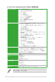
2.8 啟動選單(Boot) 本選單可讓您改變系統啟動裝置與相關功能。 2.8.1 Fast Boot [Enabled] [Enabled] 加速系統啟動速度。 [Disabled] 使系統使用正常啟動速度。 Next Boot after AC Power Loss [Normal Boot] [Normal Boot] 在電源中斷後回復至正常啟動速度。 [Fast Boot] 在電源中斷後加快啟動速度。 2.8.
2.8.4 Wait For ‘F1’ If Error [Enabled] 啟用本項目時,當系統在開機過程出現錯誤資訊,將會等待您按下 鍵確認才 會繼續進行開機程式。設定值有:[Disabled] [Enabled]。 2.8.5 Option ROM Messages [Force BIOS] [Force BIOS] 選購裝置韌體程式資訊會在開機顯示。 [Keep Current] 開機時只顯示 ASUS 標誌。 2.8.6 Interrupt 19 Capture [Disabled] 啟用本項目以允許附加 ROM 捕捉中斷 19。設定值有:[Disabled] [Enabled]。 2.8.7 Setup Mode [EZ Mode] [Advanced Mode] 本項目可讓您在 POST 之後進入 BIOS 設定程式的進階模式。 [EZ Mode] 本項目可讓您在 POST 之後進入 BIOS 設定程式的 EZ 模式。 2.8.
2.8.
Delete key 本項目用來刪除系統中的密鑰。設定值有:[Yes] [No]。 DB Management db(Authorized Signature database)包含授權認證和數位簽章等,可載入後 執行。 Set New Key 本項目可讓您從 USB 儲存裝置載入已下載的 db。 Append Key 本 項目可讓您從 USB 儲存裝置載入額外的 db,以安全的載入更多映像 檔。 db 檔案必須格式化為一個基於時間認證變量的 UEFI 變量結構。 Delete key 本項目用來刪除系統中的密鑰。設定值有:[Yes] [No]。 DBX Management dbx(revoked signature database)包含禁止使用的授權認證和數字簽章等, 不被允許載入或運作。 Set New Key 本項目可讓您從 USB 儲存裝置載入已下載的 dbx。 Append Key 本項目可讓您從 USB 儲存裝置載入額外的 dbx,使其無法載入更多 db 的 映像檔。 dbx 檔案必須格式化為一個基於時間認證變量的 UEFI 變量結構。 Delete key 本項目用來刪除系統中的密鑰
2.9 工具選單(Tools) 本工具選單可以讓您針對特別功能進行設定。請選擇選單中的選項並按下 鍵來顯示子選單。 2.9.1 ASUS EZ Flash 3 Utility 本項目可以讓您啟動華碩 EZ Flash 3 程式,按下 會出現再次確認的視 窗,請使用左右鍵選擇 [Yes] 或 [No],接著按下 確認。 請參考 2.1.2 使用華碩 EZ Flash 3 的說明。 2.9.
狀態定義:: Frozen(凍結): 這個狀態為 BIOS 的保護措施, BIOS 守衛在開機前凍 結沒有密碼保護的驅動程式。如果驅動程式被凍結,則 必須關機或必須將電腦用 Secure Erase. 執行硬體重置。 Locked(鎖定): 若 Secure Erase 執行不完整或已經停止,SSD 可能被鎖 住。這可能需要使用由華碩定義的第三方不同密碼。您 必須在使用 Secure Erase 前,先使用軟體將 SSD 解鎖。 2.9.3 Setup Animator [Disabled] 啟用或停用 Setup Animator。設定值有:[Enabled] [Disabled]。 2.9.
2.9.6 Graphics Card Information 本選單會顯示已安裝在系統內的顯示卡資訊。 僅會顯示部分 ASUS 顯示卡的資訊。 GPU Post 本項目會顯示針對安裝顯示卡之 PCIE 插槽的資訊與建議設定。 Bus Interface 本項目可以讓您選擇 bus interface。 2.
2.11 安裝作業系統 由於主機板與周邊硬體裝置的選項設定繁多,本章僅就軟體的安裝程式供 您參考。您也可以參閱您使用的作業系統說明檔案以取得更詳盡的資訊。 2.11.1 在 100 系列主機板上安裝 Windows® 7 與 USB 3.0 驅動程 式 根據晶片組規格,100 系列需要預先載入 USB 3.0 驅動程式以便在安裝 Windows® 7 作業系統的過程中使用滑鼠與鍵盤。本章節主要提供您預載 USB 3.0 驅動程式與安 裝 Windows® 7 的方法與資訊。 方法一 : 使用 SATA 光碟機 及 USB 裝置 使用華碩隨附的驅動程式及公用程式 DVD 光碟後安裝 Windows® 7。 所需項目 : ˙ 1 x 華碩驅動程式及公用程式 DVD 光碟 ˙ 1 x Windows® 7 安裝來源 ˙ 1 x SATA 光碟機 ˙ 1 x USB 裝置 (光碟機或儲存裝置) USB 儲存裝置需要 8G 或更多的儲存空間,建議您先將儲存裝置格式化 後使用。 1.
5. 選擇 USB 光碟機或 USB 儲存裝置設定為開機裝置。 6. USB 3.0 驅動程式會在安裝時自動載入。 當螢幕出現“Setup is starting...” 時,表示您已成功載入 USB 3.0 驅動 程式。 7.
方法二 : 使用修改後的 Windows® 7 ISO 檔案 使用修改後的 Windows® 7 安裝 DVD 光碟安裝 Windows® 7 與載入 USB 3.0 驅動 程式。 所需項目: ˙ 1 x 華碩驅動程式及公用程式 DVD 光碟 ˙ 1 x Windows® 7 安裝來源 ˙ 1 x SATA 光碟機 ˙ 1 x 工作系統 ( PC 或 筆記型電腦) 1. 在您工作系統上使用第三方 ISO 軟體創造一個 Windows® 7 安裝程式的 ISO 檔 案。 2. 將華碩驅動程式及公用程式 DVD 光碟目錄內的“Auto_Unattend”資料夾 及 “Auto_Unattend.xml”檔案完整複製到您的工作系。 3. 編輯並將“Auto_Unattend”資料夾 及“Auto_Unattend.xml”檔案增至 ISO 映像 檔中。 4. 將 ISO 映像檔燒錄到空白 DVD 光碟中。 5. 將修正版 Windows® 7 安裝 DVD 光碟放入 SATA 光碟機中並連接至您的 100 系 列平台。 6.
方法三 : 使用華碩 EZ 安裝程式 使用華碩 EZ 安裝程式創造一個修改後的 Windows® 7 安裝來源。 所需項目 : ˙ 1 x 華碩驅動程式及公用程式 DVD 光碟 ˙ 1 x Windows® 7 安裝 DVD 光碟 ˙ 1 x 工作系統 ( PC 或 筆記型電腦) ˙ 1 x SATA 光碟機 ˙ 1 x USB 儲存裝置 (8GB 或更多的儲存空間) 1. 放入 Windows® 7 安裝 DVD 光碟。 2. 啟動華碩驅動程式及公用程式 DVD 光碟內的華碩 EZ 安裝程式。 3.
- 選擇 Windows® 7 安裝來源後點選 Next。 - 選擇 USB 儲存裝置後點選 Next。 若 USB 儲存裝置未顯示,點選 重新整理。 - 點 選 Yes 以清除 USB 儲存裝置裡的資料後,創造一個 USB 啟動裝置。 建議您備份 USB 儲存裝置裡的資料,以避免因格式化造成資料遺失。 - 完 成後點選 OK。 華碩 B150I PRO GAMING/AURA SERIES 主機板使用手冊 2-47
Windows® 7 安裝光碟至 ISO 映像檔 - 選擇 Windows 7 OS disk to ISO file 後點選 Next。 - 勾選 I agree 後點選 Next。 - 選擇 Windows® 7 安裝來源後點選 Next。 2-48 第二章:BIOS 資訊
- 選 擇一個資料夾以儲存修改後的 Windows ® 7 安裝程式 ISO 映像檔後點選 Next。 - 完成後點選 OK。 - 將 ISO 映像檔燒錄到空白 DVD 光碟中。 4. 將 Windows® 7 的安裝程式 DVD 光碟放入 USB 光碟機或是複製光碟內的所有資 料至 USB 儲存裝置,並連接至您的 100 系列平台。 5. 請在開機自我偵測 (Power-On Self Test, POST) 時按下 。 6. 選擇 USB 光碟機或 USB 儲存裝置設定為開機裝置。 7. USB 3.0 驅動程式會在安裝時自動載入。 當螢幕出現 “Setup is starting...” 時,表示您已成功載入 USB 3.0 驅動 程式。 8.
2-50 第二章:BIOS 資訊
附錄 華碩的連絡資訊 華碩電腦公司 ASUSTeK COMPUTER INC.(台灣) 市場訊息 技術支援 地址: 台灣臺北市北投區立德路15號 電話:+886-2-2894-3447 傳真:+886-2-2890-7798 電子郵件:info@asus.com.tw 全球資訊網:http://www.asus.com/tw/ 電話:+86-21-38429911 傳真:+86-21-5866-8722 轉 9101 線上支援: http://www.asus.com/tw/support/ 華碩電腦公司 ASUSTeK COMPUTER INC.(亞太地區) 市場訊息 技術支援 地址: 台灣臺北市北投區立德路15號 電話:+886-2-2894-3447 傳真:+886-2-2890-7798 電子郵件:info@asus.com.tw 全球資訊網:http://www.asus.com/tw/ 電話:+86-21-38429911 傳真: +86-21-58668722, ext. 9101# 線上支援: http://www.asus.
ASUS COMPUTER GmbH HARKORT STR. 21-23, 40880 RATINGEN GERMANY Authorized representative in Europe: Address, City: Country: ASUS COMPUTER GmbH HARKORT STR.
DECLARATION OF CONFORMITY Per FCC Part 2 Section 2. 1077(a) Asus Computer International Responsible Party Name: 800 Corporate Way, Fremont, CA 94539. Address: Phone/Fax No: (510)739-3777/(510)608-4555 hereby declares that the product Product Name : Motherboard Model Number : B150I PRO GAMING/AURA B150I PRO GAMING/WIFI/AURA Conforms to the following specifications: FCC Part 15, Subpart B, Unintentional Radiators Supplementary Information: This device complies with part 15 of the FCC Rules.