Motherboard B250 MINING EXPERT
E13594 Second Edition October 2017 Copyright © 2017 ASUSTeK COMPUTER INC. All Rights Reserved. No part of this manual, including the products and software described in it, may be reproduced, transmitted, transcribed, stored in a retrieval system, or translated into any language in any form or by any means, except documentation kept by the purchaser for backup purposes, without the express written permission of ASUSTeK COMPUTER INC. (“ASUS”).
Contents Safety information....................................................................................... iv About this guide.......................................................................................... iv Package contents........................................................................................ vi B250 MINING EXPERT specifications summary....................................... vi Chapter 1: Product introduction Motherboard overview.....................................
Safety information Electrical safety • To prevent electrical shock hazard, disconnect the power cable from the electrical outlet before relocating the system. • When adding or removing devices to or from the system, ensure that the power cables for the devices are unplugged before the signal cables are connected. If possible, disconnect all power cables from the existing system before you add a device.
Where to find more information Refer to the following sources for additional information and for product and software updates. 1. ASUS websites The ASUS website provides updated information on ASUS hardware and software products. Refer to the ASUS contact information. 2. Optional documentation Your product package may include optional documentation, such as warranty flyers, that may have been added by your dealer. These documents are not part of the standard package.
Package contents Check your motherboard package for the following items. Motherboard ASUS B250 MINING EXPERT motherboard Cables 2 x Serial ATA 6.0 Gb/s cables Accessories 1 x I/O Shield Application DVD 1 x Support DVD Documentation User Guide If any of the above items is damaged or missing, contact your retailer.
B250 MINING EXPERT specifications summary Realtek® ALC887 8-channel* High Definition Audio CODEC Audio * Use a chassis with HD audio module in the front panel to support an 8-channel audio output.
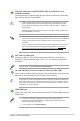
1 Product introduction Motherboard overview • Unplug the power cord from the wall socket before touching any component. • Before handling components, use a grounded wrist strap or touch a safely grounded object or a metal object, such as the power supply case, to avoid damaging them due to static electricity. • Before you install or remove any component, ensure that the ATX power supply is switched off or the power cord is detached from the power supply.
ATX power connectors (24-pin EATXPWR_A/B/C, 8-pin EATX12V, 4-pin AUXPWR_A1/A2/A3) Correctly orient the ATX power supply plugs into these connectors and push down firmly until the connectors completely fit. • In order to fully support 19 graphic cards mining, we recommend that you use 3 power supply units (PSU) that are designed for mining with sufficient 12V power plugs and provide a minimum power of 3750W in total (2*1250W + 1*1350W are recommended).
USB 3.1 Gen 1 connector (20-1 pin U31G1_12) Connect a USB 3.1 Gen 1 module to this connector for additional USB 3.1 Gen 1 front or rear panel ports. This connector complies with USB 3.1 Gen 1 specifications and provide faster data transfer speeds of up to 5 Gbps, faster charging time for USB-chargeable devices, optimized power efficiency, and backward compatibility with USB 2.0.
Front panel audio connector (10-1 pin AAFP) This connector is for a chassis-mounted front panel audio I/O module that supports either HD Audio or legacy AC`97 audio standard. Connect one end of the front panel audio I/O module cable to this connector. • We recommend that you connect a high-definition front panel audio module to this connector to avail of the motherboard’s high-definition audio capability.
LAN port LED indications Activity Link LED Activity/Link LED Status Description Speed LED Status Description Off Orange Orange (Blinking) Orange (Blinking then steady) OFF ORANGE GREEN 10Mbps connection 100Mbps connection 1Gbps connection - - No link Linked Data activity Speed LED LAN port Ready to wake up from S5 mode 5. Line In port (light blue). This port connects to the tape, CD, DVD player, or other audio sources. 6. Line Out port (lime). This port connects to a headphone or a speaker.
Central Processing Unit (CPU) This motherboard comes with a surface mount LGA1151 socket designed for the 7th/6th Generation Intel® Core™ i7 / Core™ i5 / Core™ i3, Pentium® and Celeron® processors. Unplug all power cables before installing the CPU. • Ensure that you install the correct CPU designed for the LGA1151 socket only. DO NOT install a CPU designed for LGA1150, LGA1155 and LGA1156 sockets on the LGA1151 socket.
System memory Overview This motherboard comes with two Double Data Rate 4 (DDR4) Dual Inline Memory Module (DIMM) sockets. A DDR4 module is notched differently from a DDR, DDR2, or DDR3 module. DO NOT install a DDR, DDR2, or DDR3 memory module to the DDR4 slot. DIMM_A1 DIMM_B1 1-7 Channel Sockets Channel A DIMM_A1 Channel B DIMM_B1 • You may install varying memory sizes in Channel A and Channel B. The system maps the total size of the lower-sized channel for the dual-channel configuration.
Installing a DIMM 1 2 A A B To remove a DIMM A B Expansion slots This motherboard comes with one PCIe x16 and eighteen (18) PCIe x1 expansion card slots that support graphics cards, network cards, and other cards that comply with PCIe specifications. The added expansion slots and power connectors are uniquely designed to support up to 19 mining graphics cards for professional cryptocurrency mining.
Installing mining cards Unplug the power cord before adding or removing expansion cards. Failure to do so may cause you physical injury and damage motherboard components. Graphic cards Quantity of graphic cards for mining 19* 18* 17* 16 15 14 13 12 11 10 P106 8 7-8 NVIDIA Regular cards N/A N/A AMD 9-11* 7-8 9 8 5-8 7 6 5 4 3 2 No limit 5-8 * need AMD driver support. To install mining cards: • Seven (7) or less mining cards 1.
• 8 ~ 13 mining cards To make your build more stable, when using 8 or more mining cards, we recommend that you install 4GB memory modules and change the size of the virtual memory paging file to 20GB. 1. Install your mining cards into the PCIe x16 slot and the PCIe x1 slots labeled Axx and Bxx in sequential order A01 ~ B12. 2. Connect your power supply unit (PSU) to the 24-pin EATX power connectors labeled EATXPWR_A and EATXPWR_B.
• 14 ~ 19 mining cards 1. Install your mining cards into the PCIe x16 slot and the PCIe x1 slots labeled Axx, Bxx and Cxx in sequential order A01 ~ C18. 2. Connect your power supply unit (PSU) to 24-pin EATX power connectors labeled EATXPWR_A, EATXPWR_B and EATXPWR_C.
Changing the mining mode in BIOS To change the mining mode in BIOS: 1. Press or during POST to enter BIOS Setup. 2. Go to the Advanced menu > Mining Mode. This item is set to [Enabled] by default. You can change this item by yourself. Viewing the mining card status To view the mining card status in BIOS: 1. Press or during POST to enter BIOS Setup. 2. Go to the Advanced menu > On Board Slot States, then press to display the status of the expansion cards.
To view the mining card status during POST: ® An image appears during POST to display the status of the mining cards. Working Error None • Green slot: The mining card works normally. • Red slot: There is an error with the mining card. • Gray slot: Your system failed to detect the mining card. To make your build more stable, when using 8 or more mining cards, we recommend that you install 4GB memory modules and change the size of the virtual memory paging file to 20GB.
BIOS information 2 Scan the QR code to view the BIOS update guide. BIOS setup program Use the BIOS Setup program to update the BIOS or configure its parameters. The BIOS screens include navigation keys and brief online help to guide you in using the BIOS Setup program. Entering BIOS Setup at startup To enter BIOS Setup at startup: Press or during the Power-On Self Test (POST). If you do not press or , POST continues with its routines.
EZ Mode By default, the EZ Mode screen appears when you enter the BIOS setup program. The EZ Mode provides you an overview of the basic system information, and allows you to select the display language, system performance mode, fan profile and boot device priority. To access the Advanced Mode, click Advanced Mode(F7) or press . The default screen for entering the BIOS setup program can be changed. Refer to the Setup Mode item under the Boot menu for details.
Advanced Mode The Advanced Mode provides advanced options for experienced end-users to configure the BIOS settings. The figure below shows an example of the Advanced Mode. Refer to the following sections for the detailed configurations. To access the EZ Mode, click EzMode(F7) or press .
Search on FAQ Move your mouse over this button to show a QR code. Scan this QR code with your mobile device to connect to the ASUS BIOS FAQ web page. You can also scan the QR code below. Exit menu The Exit menu items allow you to load the optimal default values for the BIOS items, and save or discard your changes to the BIOS items. Load Optimized Defaults This option allows you to load the default values for each of the parameters on the Setup menus.
Appendix Notices Federal Communications Commission Statement This device complies with Part 15 of the FCC Rules. Operation is subject to the following two conditions: • This device may not cause harmful interference. • This device must accept any interference received including interference that may cause undesired operation. This equipment has been tested and found to comply with the limits for a Class B digital device, pursuant to Part 15 of the FCC Rules.
VCCI: Japan Compliance Statement Class B ITE KC: Korea Warning Statement REACH Complying with the REACH (Registration, Evaluation, Authorisation, and Restriction of Chemicals) regulatory framework, we published the chemical substances in our products at ASUS REACH website at http://csr.asus.com/english/REACH.htm. DO NOT throw the motherboard in municipal waste. This product has been designed to enable proper reuse of parts and recycling.
Google™ License Terms Copyright© 2017 Google Inc. All Rights Reserved. Licensed under the Apache License, Version 2.0 (the “License”); you may not use this file except in compliance with the License. You may obtain a copy of the License at: http://www.apache.org/licenses/LICENSE-2.0 Unless required by applicable law or agreed to in writing, software distributed under the License is distributed on an “AS IS” BASIS, WITHOUT WARRANTIES OR CONDITIONS OF ANY KIND, either express or implied.
ASUS contact information ASUSTeK COMPUTER INC. Address Telephone Fax Web site Technical Support Telephone Fax Online support 4F, No. 150, Li-Te Road, Peitou, Taipei 112, Taiwan +886-2-2894-3447 +886-2-2890-7798 www.asus.com +86-21-38429911 +86-21-5866-8722, ext. 9101# http://qr.asus.com/techserv ASUS COMPUTER INTERNATIONAL (America) Address 800 Corporate Way, Fremont, CA 94539, USA Telephone +1-510-739-3777 Fax +1-510-608-4555 Web site http://www.asus.
DECLARATION OF CONFORMITY Per FCC Part 2 Section 2. 1077(a) Asus Computer International Responsible Party Name: 800 Corporate Way, Fremont, CA 94539. Address: Phone/Fax No: (510)739-3777/(510)608-4555 hereby declares that the product Product Name : Motherboard Model Number : B250 MINING EXPERT Conforms to the following specifications: FCC Part 15, Subpart B, Unintentional Radiators Supplementary Information: This device complies with part 15 of the FCC Rules.