B250M-C PRO/ CSM Motherboard B250M-C PRO
E13586 Revised Edition October 2017 Copyright © 2017 ASUSTeK COMPUTER INC. All Rights Reserved. No part of this manual, including the products and software described in it, may be reproduced, transmitted, transcribed, stored in a retrieval system, or translated into any language in any form or by any means, except documentation kept by the purchaser for backup purposes, without the express written permission of ASUSTeK COMPUTER INC. (“ASUS”).
Contents Safety information....................................................................................... iv About this guide.......................................................................................... iv Package contents........................................................................................ vi B250M-C PRO specifications summary..................................................... vi Chapter 1 : Product introduction Motherboard overview.............................
Safety information Electrical safety • To prevent electrical shock hazard, disconnect the power cable from the electrical outlet before relocating the system. • When adding or removing devices to or from the system, ensure that the power cables for the devices are unplugged before the signal cables are connected. If possible, disconnect all power cables from the existing system before you add a device.
Where to find more information Refer to the following sources for additional information and for product and software updates. 1. ASUS websites The ASUS website provides updated information on ASUS hardware and software products. Refer to the ASUS contact information. 2. Optional documentation Your product package may include optional documentation, such as warranty flyers, that may have been added by your dealer. These documents are not part of the standard package.
Package contents Check your motherboard package for the following items. Motherboard ASUS B250M-C PRO motherboard Cables 2 x Serial ATA 6.0 Gb/s cables Accessories 1 x ASUS I/O Shield 1 x M.2 Screw package Application DVD Support DVD Documentation User Guide If any of the above items is damaged or missing, contact your retailer.
B250M-C PRO specifications summary Audio Realtek® ALC887 8-channel High Definition Audio CODEC - Supports jack-detection and front panel jack-retasking Multi-GPU support Cross Fire X LAN Intel® I219V Gigabit LAN Controller USB Intel® B250 Chipset: - 6 x USB 3.0/2.0 ports (2 ports at mid-board; 4 ports at back panel) - 6 x USB 2.0/1.
B250M-C PRO specifications summary 1 x 24-pin EATX Power connector 1 x 4-pin ATX 12V Power connector 1 x Speaker connector 2 x COM headers Internal connectors 1 x LPT header 1 x Chassis Intrusion header 1 x Clear CMOS header 1 x MONO-out header(with AMP IC) 1 x 14-1 pin TPM header BIOS features 64 Mb Flash ROM, UEFI AMI BIOS, PnP, DMI3.0, WfM2.0, SM BIOS 3.0, ACPI 5.1, Multi-language BIOS, ASUSbackup, LOGO flash, ME update, DMI value edit, BIOS value edit Manageability WfM 2.0, DMI 3.
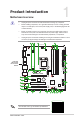
1 Product introduction Motherboard overview • Unplug the power cord from the wall socket before touching any component. • Before handling components, use a grounded wrist strap or touch a safely grounded object or a metal object, such as the power supply case, to avoid damaging them due to static electricity. • Before you install or remove any component, ensure that the ATX power supply is switched off or the power cord is detached from the power supply.
CPU and chassis fan connectors (4-pin CPU_FAN, 4-pin CHA_FAN1/2) Connect the fan cables to the fan connectors on the motherboard, ensuring that the black wire of each cable matches the ground pin of the connector. Do not forget to connect the fan cables to the fan connectors. Insufficient air flow inside the system may damage the motherboard components. These are not jumpers! Do not place jumper caps on the fan connectors! The CPU_FAN connector supports a CPU fan of maximum 1A (12 W) fan power.
Intel® B250 Serial ATA 6.0Gb/s connectors (7-pin SATA6G_1~6) These connectors connect to Serial ATA 6.0 Gb/s hard disk drives via Serial ATA 6.0 Gb/s signal cables. When using hot-plug and NCQ, set the SATA Mode Selection item in the BIOS to [AHCI]. USB 3.0 connector (20-1 pin USB3_12) Connect a USB 3.0 module to this connector for additional USB 3.0 front or rear panel ports. This connector complies with USB 3.
Chassis intrusion header (4-1 pin CHASSIS) This header is for a chassis-mounted intrusion detection sensor or switch. Connect one end of the chassis intrusion sensor or switch cable to this connector. The chassis intrusion sensor or switch sends a high-level signal to this connector when a chassis component is removed or replaced. The signal is then generated as a chassis intrusion event. By default, the pin labeled “Chassis Signal” and “Ground” are shorted with a jumper cap.
Rear panel connectors 2 1 3 10 4 8 9 5 6 8 7 1. PS/2 mouse port (green). This port is for a PS/2 mouse. 2. DVI-I port. This port is for any DVI-I compatible device. 3. DisplayPorts. These ports are for a DisplayPort-compatible device. 4. LAN (RJ-45) port. This port allows Gigabit connection to a Local Area Network (LAN) through a network hub.
Audio 2.1, 4.1, 5.1, or 7.1-channel configuration Headset 2.1-channel Port Light Blue (Rear panel) Lime (Rear panel) Pink (Rear panel) Lime (Front panel) 4.1-channel 5.1-channel 7.1-channel Line In Rear Speaker Out Rear Speaker Out Rear Speaker Out Line Out Mic In - Front Speaker Out Mic In - Front Speaker Out Bass/Center - Front Speaker Out Bass/Center Side Speaker Out To configure a 7.1-channel audio output: Use a chassis with HD audio module in the front panel to support a 7.
Central Processing Unit (CPU) This motherboard comes with a surface mount LGA1151 socket designed for 7th / 6th Generation Intel® Core™ i7 / i5 / i3, Pentium®, and Celeron® processors. Unplug all power cables before installing the CPU. • Ensure that you install the correct CPU designed for the LGA1151 socket only. DO NOT install a CPU designed for LGA1150, LGA1155 and LGA1156 sockets on the LGA1151 socket.
System memory Overview This motherboard comes with four Double Data Rate 4 (DDR4) Dual Inline Memory Module (DIMM) sockets. A DDR4 module is notched differently from a DDR, DDR2, or DDR3 module. DO NOT install a DDR, DDR2, or DDR3 memory module to the DDR4 slot. DIMM_A1 DIMM_A2 DIMM_B1 DIMM_B2 Channel Channel A Channel B Sockets DIMM_A1 & DIMM_A2 DIMM_B1 & DIMM_B2 • You may install varying memory sizes in Channel A and Channel B.
Recommended memory configuration Installing a DIMM 1 2 A A B To remove a DIMM A B ASUS B250M-C PRO 1-9
BIOS information 2 Scan the QR code to view the BIOS update guide. BIOS setup program Use the BIOS Setup program to update the BIOS or configure its parameters. The BIOS screens include navigation keys and brief online help to guide you in using the BIOS Setup program. Entering BIOS Setup at startup To enter BIOS Setup at startup: Press or during the Power-On Self Test (POST). If you do not press or , POST continues with its routines.
BIOS menu screen General Help Menu bar Main Aptio Setup Utility - Copyright (C) 2016 American Megatrends, Inc. Ai Tweaker Advanced Monitor Boot Tool Exit BIOS Information BIOS Version Build Date ME Firmware Version PCH Stepping Processor Information Brand String CPU Speed Total Memory Memory Frequency 0205 x64 03/24/2017 11.6.0.1126 AO Intel(R)Core(TM)CPU G3900TE @ 2.
Exit menu The Exit menu items allow you to load the optimal default values for the BIOS items, and save or discard your changes to the BIOS items. Main Aptio Setup Utility - Copyright (C) 2016 American Megatrends, Inc. Ai Tweaker Advanced Monitor Boot Tool Exit Load Optimized Defaults Save Changes & Reset Discard Changes & Exit Launch EFI Shell from USB drives Exit system setup without saving any changes. :Select Screen : Select Item Enter: Select +/-: Change Opt.
Appendix Notices Federal Communications Commission Statement This device complies with Part 15 of the FCC Rules. Operation is subject to the following two conditions: • This device may not cause harmful interference. • This device must accept any interference received including interference that may cause undesired operation. This equipment has been tested and found to comply with the limits for a Class B digital device, pursuant to Part 15 of the FCC Rules.
Compliance Statement of Innovation, Science and Economic Development Canada (ISED) This Class B digital apparatus complies with Canadian ICES-003, RSS-210, and CAN ICES3(B)/NMB-3(B). This device complies with Industry Canada license exempt RSS standard(s). Operation is subject to the following two conditions: (1) this device may not cause interference, and (2) this device must accept any interference, including interference that may cause undesired operation of the device.
REACH Complying with the REACH (Registration, Evaluation, Authorisation, and Restriction of Chemicals) regulatory framework, we published the chemical substances in our products at ASUS REACH website at http://csr.asus.com/english/REACH.htm. DO NOT throw the motherboard in municipal waste. This product has been designed to enable proper reuse of parts and recycling.
English ASUSTeK Computer Inc. hereby declares that this device is in compliance with the essential requirements and other relevant provisions of related Directives. Full text of EU declaration of conformity is available at: www.asus.com/support Français AsusTek Computer Inc. déclare par la présente que cet appareil est conforme aux critères essentiels et autres clauses pertinentes des directives concernées. La déclaration de conformité de l’UE peut être téléchargée à partir du site Internet suivant : www.
ASUS contact information ASUSTeK COMPUTER INC. Address Telephone Fax Web site Technical Support Telephone Fax Online support 4F, No. 150, Li-Te Road, Peitou, Taipei 112, Taiwan +886-2-2894-3447 +886-2-2890-7798 www.asus.com +86-21-38429911 +86-21-5866-8722, ext. 9101# http://qr.asus.com/techserv ASUS COMPUTER INTERNATIONAL (America) Address 800 Corporate Way, Fremont, CA 94539, USA Telephone +1-510-739-3777 Fax +1-510-608-4555 Web site http://www.asus.
DECLARATION OF CONFORMITY Per FCC Part 2 Section 2. 1077(a) Asus Computer International Responsible Party Name: 800 Corporate Way, Fremont, CA 94539. Address: Phone/Fax No: (510)739-3777/(510)608-4555 hereby declares that the product Product Name : Motherboard Model Number : B250M-C PRO Conforms to the following specifications: FCC Part 15, Subpart B, Unintentional Radiators Supplementary Information: This device complies with part 15 of the FCC Rules.