Motherboard B85-A R2.
E9137 First Edition V1 March 2014 Copyright © 2014 ASUSTeK COMPUTER INC. All Rights Reserved. No part of this manual, including the products and software described in it, may be reproduced, transmitted, transcribed, stored in a retrieval system, or translated into any language in any form or by any means, except documentation kept by the purchaser for backup purposes, without the express written permission of ASUSTeK COMPUTER INC. (“ASUS”).
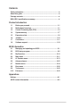
Contents Safety information....................................................................................... iv About this guide.......................................................................................... iv Package contents........................................................................................ vi B85-A R2.0 specifications summary.......................................................... vi Product introduction 1.1 Before you proceed....................................
Safety information Electrical safety • To prevent electrical shock hazard, disconnect the power cable from the electrical outlet before relocating the system. • When adding or removing devices to or from the system, ensure that the power cables for the devices are unplugged before the signal cables are connected. If possible, disconnect all power cables from the existing system before you add a device.
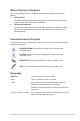
Where to find more information Refer to the following sources for additional information and for product and software updates. 1. ASUS websites The ASUS website provides updated information on ASUS hardware and software products. Refer to the ASUS contact information. 2. Optional documentation Your product package may include optional documentation, such as warranty flyers, that may have been added by your dealer. These documents are not part of the standard package.
Package contents Check your motherboard package for the following items. Motherboard ASUS B85-A R2.0 motherboard Cables 2 x Serial ATA 6.0 Gb/s cables Accessories 1 x I/O Shield Application DVD Support DVD Documentation User Guide If any of the above items is damaged or missing, contact your retailer. B85-A R2.
B85-A R2.0 specifications summary Audio Realtek® ALC887 8-channel High Definition Audio CODEC - Supports jack-detection, multi-streaming and front panel jack-retasking * Use a chassis with HD audio module in the front panel to support an 8-channel audio output. Storage Intel® B85 Express Chipset: - 2 x Serial ATA 3.0 Gb/s connectors - 4 x Serial ATA 6.0 Gb/s connectors Supports Intel® Rapid Start Technology, Intel® Smart Connect Technology* * These functions will work depending on the CPU installed.
B85-A R2.0 specifications summary Back Panel I/O ports 1 x PS/2 keyboard port (purple) 1 x PS/2 mouse port (green) 1 x DVI port 1 x D-Sub port 1 x LAN (RJ-45) port 4 x USB 2.0/1.1 ports 2 x USB 3.0/2.0 ports 3 x Audio jacks support 8-channel audio output Internal connectors 1 x USB 3.0 connector supports additional 2 USB 3.0 ports 2 x USB 2.0 connectors support additional 4 USB 2.0 ports 1 x System panel connector 1 x S/PDIF connector 1 x Front panel audio connector (AAFP) 2 x SATA 3.
Product introduction 1.1 Before you proceed 1 Take note of the following precautions before you install motherboard components or change any motherboard settings. 1.2 • Unplug the power cord from the wall socket before touching any component. • Before handling components, use a grounded wrist strap or touch a safely grounded object or a metal object, such as the power supply case, to avoid damaging them due to static electricity. • Hold components by the edges to avoid touching the ICs on them.
Place this side towards the rear of the chassis 1.2.3 B85-A R2.0 Motherboard layout 1 2 3 1 4 5 20.8cm(8.2in) CPU_FAN KBMS DIGI +VRM BATTERY CHA_FAN1 PCIEX1_1 B85-A R2.0 Realtek 8111GR Super I/O SATA6G_2 USB3_12 AUDIO SATA6G_1 LAN_USB34 2 30.5cm(12.
1.2.4 Layout contents Connectors/Slots/LED 1. CPU and chassis fan connectors (4-pin CPU_FAN, 4-pin CHA_FAN1) 2. ATX power connectors (24-pin EATXPWR, 8-pin EATX12V) 3. Intel® LGA1150 CPU socket 4. DDR3 DIMM slots 5. USB 3.0 connector (20-1 pin USB3_12) 6. Intel® B85 Serial ATA 6.0Gb/s connectors (7-pin SATA6G_1~4) 7. Clear RTC RAM (2-pin CLRTC) 8. Intel® B85 Serial ATA 3.0Gb/s connectors (7-pin SATA3G_1~2) 9. System panel connector (20-8 pin F_PANEL) 10. USB 2.0 connectors (10-1 pin USB11~14) 11.
Unplug all power cables before installing the CPU. 1.3.1 • Ensure that you install the correct CPU designed for the LGA1150 socket only. DO NOT install a CPU designed for LGA1155 and LGA1156 sockets on the LGA1150 socket. • Upon purchase of the motherboard, ensure that the PnP cap is on the socket and the socket contacts are not bent. Contact your retailer immediately if the PnP cap is missing, or if you see any damage to the PnP cap/socket contacts/motherboard components.
4 5 C A B 1.3.2 CPU heatsink and fan assembly installation Apply the Thermal Interface Material to the CPU heatsink and CPU before you install the heatsink and fan if necessary. ASUS B85-A R2.
To install the CPU heatsink and fan assembly 1 2 A B B A 3 4 To uninstall the CPU heatsink and fan assembly 1 2 A B B A 1-6 Chapter 1: Product introduction
1.4 System memory 1.4.1 Overview This motherboard comes with four Double Data Rate 3 (DDR3) Dual Inline Memory Module (DIMM) sockets. A DDR3 module is notched differently from a DDR or DDR2 module. DO NOT install a DDR or DDR2 memory module to the DDR3 slot. DIMM_A1 DIMM_A2 DIMM_B1 DIMM_B2 According to Intel® CPU spec, DIMM voltage below 1.65V is recommended to protect the CPU. Channel Channel A Channel B Sockets DIMM_A1 & DIMM_A2 DIMM_B1 & DIMM_B2 B85-A R2.0 B85-A R2.
1.4.3 • The default memory operation frequency is dependent on its Serial Presence Detect (SPD), which is the standard way of accessing information from a memory module. • For system stability, use a more efficient memory cooling system to support a full memory load (4 DIMMs). • Visit the ASUS website at: www.asus.com for the latest QVL.
To remove a DIMM B A A 1.5 Expansion slots In the future, you may need to install expansion cards. The following sub‑sections describe the slots and the expansion cards that they support. Unplug the power cord before adding or removing expansion cards. Failure to do so may cause you physical injury and damage motherboard components. 1.5.1 Installing an expansion card To install an expansion card: 1.
1.5.3 PCI slots The PCI slot supports cards such as a LAN card, SCSI card, USB card, and other cards that comply with PCI specifications. 1.5.4 PCI Express 2.0 x1 slot This motherboard supports PCI Express x1 network cards, SCSI cards, and other cards that comply with the PCI Express specifications. 1.5.5 PCI Express x16 slots This motherboard has two PCI Express x16 slots that support PCI Express x16 graphic cards complying with the PCI Express specifications.
B85-A R2.0 CLRTC Normal (Default) Clear RTC B85-A R2.0 Clear RTC RAM To erase the RTC RAM: 1. Turn OFF the computer and unplug the power cord. 2. Use a metal object such as a screwdriver to short the two pins. 3. Plug the power cord and turn ON the computer. 4. Hold down the key during the boot process and enter BIOS setup to reenter data. • If the steps above do not help, remove the onboard battery and short the two pins again to clear the CMOS RTC RAM data.
1. PS/2 mouse port (green). This port is for a PS/2 mouse. 2. Video Graphics Adapter (VGA) port. This 15-pin port is for a VGA monitor or other VGA-compatible devices. 3. LAN (RJ-45) port. This port allows Gigabit connection to a Local Area Network (LAN) through a network hub.
• Due to USB 3.0 controller limitations, USB 3.0 devices can only be used under a Windows® OS environment and after USB 3.0 driver installation. • The plugged USB 3.0 device may run on xHCI or EHCI mode, depending on the operating system’s setting. • USB 3.0 devices can only be used for data storage. • We strongly recommend that you connect USB 3.0 devices to USB 3.0 ports for faster and better performance from your USB 3.0 devices.
2. ATX power connectors (24-pin EATXPWR, 8-pin EATX12V) These connectors are for ATX power supply plugs. The power supply plugs are designed to fit these connectors in only one orientation. Find the proper orientation and push down firmly until the connectors completely fit. +12V DC +12V DC +12V DC +12V DC EATX12V +3 Volts +12 Volts +12 Volts +5V Standby Power OK GND +5 Volts GND +5 Volts GND +3 Volts +3 Volts GND GND GND GND B85-A R2.
4. Front panel audio connector (10-1 pin AAFP) B85-A R2.0 NC AGND NC NC PIN 1 HD-audio-compliant pin definition MIC2 MICPWR Line out_R NC Line out_L PIN 1 PORT1 L PORT1 R PORT2 R SENSE_SEND PORT2 L AAFP SENSE2_RETUR AGND NC SENSE1_RETUR This connector is for a chassis-mounted front panel audio I/O module that supports either HD Audio or legacy AC`97 audio standard. Connect one end of the front panel audio I/O module cable to this connector. Legacy ACʼ97 compliant definition B85-A R2.
6. USB 3.0 connector (20-1 pin USB3_12) This connector allows you to connect a USB 3.0 module for additional USB 3.0 front or rear panel ports. With an installed USB 3.0 module, you can enjoy all the benefits of USB 3.0 including faster data transfer speeds of up to 5Gbps, faster charging time for USB-chargeable devices, optimized power efficiency, and backward compatibility with USB 2.0. USB3_12 PIN 1 B85-A R2.
8. Intel® B85 Serial ATA 6.0Gb/s connectors (7-pin SATA6G_1~4) These connectors connect to Serial ATA 6.0 Gb/s hard disk drives via Serial ATA 6.0 Gb/s signal cables. SATA6G_1 GND RSATA_TXP1 RSATA_TXN1 GND RSATA_RXN1 RSATA_RXP1 GND SATA6G_2 GND RSATA_TXP2 RSATA_TXN2 GND RSATA_RXN2 RSATA_RXP2 GND SATA6G_4 SATA6G_3 GND RSATA_RXP4 RSATA_RXN4 GND RSATA_TXN4 RSATA_TXP4 GND GND RSATA_RXP3 RSATA_RXN3 GND RSATA_TXN3 RSATA_TXP3 GND B85-A R2.0 B85-A R2.0 SATA 6.
9. System panel connector (10-1 pin PANEL) This connector supports several chassis-mounted functions. PANEL SPEAKER +5V Ground Ground Speaker PWR_LED- PWR_LED+ PWR_LED Reset Ground HDD_LED PWRSW RESET HDD_LED+ HDD_LED- PWR Ground PIN 1 B85-A R2.0 * Requires an ATX power supply B85-A R2.0 System panel connector • System power LED (2-pin PWR_LED) This 2-pin connector is for the system power LED. Connect the chassis power LED cable to this connector.
1.8 1.8.1 Software support Installing an operating system This motherboard supports Windows® 7 (32bit/64bit), Windows® 8 (32bit/64bit) and Windows® 8.1 (32bit/64bit) Operating Systems (OS). Always install the latest OS version and corresponding updates to maximize the features of your hardware. Motherboard settings and hardware options vary. Refer to your OS documentation for detailed information. 1.8.
1-20 Chapter 1: Product introduction
BIOS information 2.1 Managing and updating your BIOS 2 Save a copy of the original motherboard BIOS file to a USB flash disk in case you need to restore the BIOS in the future. Copy the original motherboard BIOS using the ASUS Update utility. 2.1.1 EZ Update EZ Update is a utility that allows you to automatically update your motherboard’s softwares, drivers and the BIOS version easily. With this utlity, you can also manually update the saved BIOS and select a boot logo when the system goes into POST.
2.1.2 ASUS EZ Flash 2 The ASUS EZ Flash 2 feature allows you to update the BIOS without using an OS‑based utility. Before you start using this utility, download the latest BIOS file from the ASUS website at www.asus.com. To update the BIOS using EZ Flash 2: 2-2 1. Insert the USB flash disk that contains the latest BIOS file to the USB port. 2. Enter the Advanced Mode of the BIOS setup program. Go to the Tool menu to select ASUS EZ Flash Utility and press to enable it. 3.
2.1.3 ASUS CrashFree BIOS 3 utility The ASUS CrashFree BIOS 3 is an auto recovery tool that allows you to restore the BIOS file when it fails or gets corrupted during the updating process. You can restore a corrupted BIOS file using the motherboard support DVD or a USB flash drive that contains the updated BIOS file. • Before using this utility, rename the BIOS file in the removable device into B85AR2.CAP. • The BIOS file in the support DVD may not be the latest version.
Booting the system to a DOS environment 1. Insert the USB flash drive with the latest BIOS file and BIOS Updater to the USB port. 2. Boot your computer. When the ASUS Logo appears, press to show the BIOS Boot Device Select Menu. Insert the support DVD into the optical drive and select the optical drive as the boot device. 3. When the Make Disk menu appears, select the FreeDOS command prompt item by pressing the item number. 4.
3. Press to switch between screen fields and use the keys to select the BIOS file and press . BIOS Updater checks the selected BIOS file and prompts you to confirm BIOS update. 4. Select Yes and press . When BIOS update is done, press to exit BIOS Updater. Restart your computer. DO NOT shut down or reset the system while updating the BIOS to prevent system boot failure! • For BIOS Updater version 1.
2.2 BIOS setup program Use the BIOS Setup program to update the BIOS or configure its parameters. The BIOS screens include navigation keys and brief online help to guide you in using the BIOS Setup program. Entering BIOS Setup at startup To enter BIOS Setup at startup: • Press during the Power-On Self Test (POST). If you do not press , POST continues with its routines. Entering BIOS Setup after POST To enter BIOS Setup after POST: • Press ++ simultaneously.
EZ Mode By default, the EZ Mode screen appears when you enter the BIOS setup program. The EZ Mode provides you an overview of the basic system information, and allows you to select the display language, system performance mode and boot device priority. To access the Advanced Mode, click Exit/Advanced Mode, then select Advanced Mode or press F7 for the advanced BIOS settings. The default screen for entering the BIOS setup program can be changed. Refer to the Setup Mode item in section 2.
Back button Menu items Menu bar Configuration fields Pop-up window Submenu item General help Navigation keys Scroll bar Last modified settings Menu bar Quick note The menu bar on top of the screen has the following main items: My Favorites For saving the frequently-used system settings and configuration Main For changing the basic system configuration Ai Tweaker For changing the overclocking settings Advanced Boot For changing the advanced system settings For displaying the system temperature
Pop-up window Select a menu item and press to display a pop-up window with the configuration options for that item. Scroll bar A scroll bar appears on the right side of a menu screen when there are items that do not fit on the screen. Press the Up/Down arrow keys or / keys to display the other items on the screen. Navigation keys At the bottom right corner of the menu screen are the navigation keys for the BIOS setup program.
2.3 My Favorites MyFavorites is your personal space where you can easily save and access your favorite BIOS items. Adding items to My Favorites To add frequently-used BIOS items to My Favorites: 1. Use the arrow keys to select an item that you want to add. When using a mouse, hover the pointer to the item. 2. Press on your keyboard or right-click on your mouse to add the item to My Favorites page.
2.4 Main menu 2.4.1 System Language [English] The Main menu screen appears when you enter the Advanced Mode of the BIOS Setup program. The Main menu provides you an overview of the basic system information, and allows you to set the system date, time, language, and security settings. Allows you to choose the BIOS language version from the options. Configuration options: [English] [Español] [Русский] [한국어] 2.4.2 System Date [Day xx/xx/xxxx] Allows you to set the system date. 2.4.
Administrator Password If you have set an administrator password, we recommend that you enter the administrator password for accessing the system. Otherwise, you might be able to see or change only selected fields in the BIOS setup program. To set an administrator password: 1. Select the Administrator Password item and press . 2. From the Create New Password box, key in a password, then press . 3. Confirm the password when prompted. To change an administrator password: 1.
2.5 Ai Tweaker menu The Ai Tweaker menu items allow you to configure overclocking-related items. Be cautious when changing the settings of the Ai Tweaker menu items. Incorrect field values can cause the system to malfunction. The configuration options for this section vary depending on the CPU and DIMM model you installed on the motherboard. Scroll down to display the following items: ASUS B85-A R2.
Scroll down to display the following items: Target CPU Turbo-Mode Speed : xxxxMHz Displays the target CPU Turbo-Mode speed. Target DRAM Speed : xxxxMHz Displays the target DRAM speed. Target Cache Speed : xxxxMHz Displays the target Cache speed. Target DMI/PEG Clock : xxxxMHz Displays the target DMI/PEG clock. Target iGPU Speed : xxxxMHz Displays the target iGPU speed. 2.5.1 Ai Overclock Tuner [Auto] Allows you to select the CPU overclocking options to achieve the desired CPU internal frequency.
The following two items appear only when you set the CPU Core Ratio to [Sync All Cores] or [Per Core]. 1-Core Ratio Limit [Auto] Allows you to set the 1-Core Ratio Limit. Select [Auto] to apply the CPU default Turbo Ratio setting or manually assign a 1-Core Ratio Limit value that is higher than or equal to the 2-Core Ratio Limit. 2-Core Ratio Limit [Auto] This item becomes configurable only when you set CPU Core Ratio to [Per Core] and allows you to set the 2-Core Ratio Limit.
2.5.7 Max. CPU Graphics Ratio [Auto] [Auto] The CPU Graphics Max. ratio is set to its optimized setting depending on the system loading. [Manaul] Use the <+> or <-> keys to adjust the optimal CPU Graphics Max. ratio. The value may vary depending on the system loading. 2.5.8 GPU Boost [As is] GPU Boost accelerates the integrated GPU for extreme graphics performance. Configuration options: [As Is] [Enabled]. 2.5.
Configuration options: [Auto] [1 DRAM Clock] – [65535 DRAM Clock] DRAM WRITE Recovery Time [Auto] Configuration options: [Auto] [1 DRAM Clock] – [16 DRAM Clock] DRAM READ to PRE Time [Auto] Configuration options: [Auto] [1 DRAM Clock] – [15 DRAM Clock] DRAM FOUR ACT WIN Time [Auto] Configuration options: [Auto] [1 DRAM Clock] – [255 DRAM Clock] DRAM WRITE to READ Delay [Auto] Configuration options: [Auto] [1 DRAM Clock] – [15 DRAM Clock] DRAM CKE Minimum pulse width [Auto] Configuration options: [Auto] [1 D
tWRWR_dr [Auto] Configuration options: [Auto] [1 DRAM Clock] – [15 DRAM Clock] tWRWR_dd [Auto] Configuration options: [Auto] [1 DRAM Clock] – [15 DRAM Clock] Dec_WRD [Auto] Configuration options: [Auto] [0] [1] tRDWR [Auto] Configuration options: [Auto] [1 DRAM Clock] – [31 DRAM Clock] tRDWR_dr [Auto] Configuration options: [Auto] [1 DRAM Clock] – [31 DRAM Clock] tRDWR_dd [Auto] Configuration options: [Auto] [1 DRAM Clock] – [31 DRAM Clock] MISC MRC Fast Boot [Enabled] Allows you to enable or disable the MR
CPU Fixed Frequency [XXX] This item allows you to set a fixed CPU frequency. Use the <+> or <-> keys to adjust the value. The values range from 200kHz to 350kHz with a 50kHz interval. CPU Power Phase Control [Auto] Allows you to set the power phase based on the CPU. Configuration options: [Auto] [Standard] [Optimized] [Extreme] [Manual Adjustment] DO NOT remove the thermal module when setting this item to [Extreme] and [Manual Adjustment]. The thermal conditions should be monitored.
• Turbo Mode is only available on selected CPU models only. • The following first three items appear only when you set the Turbo Mode to [Enabled]. Turbo Mode Parameters Long Duration Package Power Limit [Auto] Allows you to limit the turbo ratio’s long duration package power. Use the <+> and <-> keys to adjust the value. Package Power Time Window [Auto] Allows you to set the package power time window. Use the <+> and <-> keys to adjust the value.
Power Current Slope [Auto] Allows you to set the power current slope. Configuration options: [Auto] [Level -4] ~ [Level 4]. Power Current Offset [Auto] Allows you to set the power current offset. Configuration options: [Auto] [100%] [87.5%] [75%] [62.5%] [50%] [37.5%] [25%] [12.5%] [0%] [-12.5%] [-25%] [-37.5%] [-50.0%] [-62.5%] [-75%] [-87.5%] [-100%] Power Fast Ramp Response [Auto] Allows you to increase to enhance the response of the voltage regulator during the load transient. Configurations: [Auto] [0.
CPU Core Voltage Offset [Auto] This item appears only when you set the CPU Core Voltage to [Offset Mode] or [Adaptive Mode] and allows you to set the CPU core voltage offset. The values range from 0.001V to 0.999V with a 0.001V interval. Additional Turbo Mode CPU Core Voltage [Auto] This item appears only when you set the CPU Core Voltage to [Adaptive Mode] and allows you to set the additional turbo mode CPU core voltage. The values range from 0.001V to 1.920V with a 0.001V interval.
2.5.16 CPU Graphics Voltage [Auto] This item allows you to set the CPU graphics voltage. Increase the graphics voltage when increasing the iGPU frequency. Configuration options: [Auto] [Manual Mode] [Offset Mode] [Adaptive Mode]. [Adaptive Mode] is available for some specific CPU types. CPU Graphics Voltage Override [Auto] This item appears only when you set the CPU Graphics Voltage to [Manual Mode] and allows you to set the CPU graphics voltage override. The values range from 0.001V to 1.920V with a 0.
2.5.19 CPU Digital I/O Voltage Offset Mode Sign [+] This item allows you to set the CPU digital I/O voltage offset mode sign. Configuration options: [+] [-]. CPU Digital I/O Voltage Offset [Auto] This item allows you to set the CPU digital I/O voltage offset. Increase the value when increasing DRAM frequency. The values range from 0.001V to 0.999V with a 0.001V interval. 2.5.20 SVID Support [Auto] Disabling SVID Support stops the processor from commmunicating with the external voltage regulator.
2.5.26 DRAM DATA REF Voltage on CHA [Auto] Allows you to set the DRAM DATA REF Voltage on CHA. The values range from 0.3950x to 0.6300x with a 0.0050x interval 2.5.27 DRAM DATA REF Voltage on CHB [Auto] Allows you to set the DRAM DATA REF Voltage on CHB. The values range from 0.3950x to 0.6300x with a 0.0050x interval 2.5.28 CPU Spread Spectrum [Auto] [Auto] Automatic configuration. [Disabled] Enhances the BCLK overclocking ability. [Enabled] Sets to [Enabled] for EMI control. 2.
2.6.1 CPU Configuration The items in this menu show the CPU-related information that the BIOS automatically detects. The items shown in submenu may be different due to the CPU you installed. Intel® Adaptive Thermal Monitor [Enabled] [Enabled] Enables the overheated CPU to throttle its clock speed to cool down. [Disabled] Disables the CPU thermal monitor function.
Boot performance mode [Max Non-Tu...] This item allows you to select the boot performance mode. Configuration options: [Max NonTurbo Performance] [Max battery] [Turbo Performance] CPU Power Management Configuration This item allows you to manage and configure the CPU’s power. EIST [Enabled] Allows you to enable or disable the Enhanced Intel® SpeedStep Technology (EIST). [Disabled] The CPU runs at its default speed. [Enabled] The operating system controls the CPU speed.
Package C State Support [Auto] Allows you to disable or enable the whole C-State package support. Configuration options: [Auto] [Enabled] [C0/C1] [C2] [C3] [C6] [CPU C7] [CPU C7s] 2.6.2 PCH Configuration PCI Express Configuration DMI Link ASPM Control [Auto] Allows you to control the Active State Power Managemennt on both NB and SB side of the DMI Link. Configuration options: [Auto] [Enabled] [Disabled] ASPM Support [Disabled] Allows you to set the ASPM support.
Intel® Smart Connect Technology [Disabled] ICST Configuration [Disabled] Allows you to enable or disable the ISCT configuration. Configuration options: [Enabled] [Disabled] 2.6.3 SATA Configuration While entering Setup, the BIOS automatically detects the presence of SATA devices. The SATA Port items show Not Present if no SATA device is installed to the corresponding SATA port. SATA Mode Selection [AHCI] Allows you to set the SATA configuration. [Disabled] Disables the SATA function.
CPU Audio Device [Disabled] Allows you to enable or disable CPU SA Audio Device. Configuration options: [Enabled] [Disabled] Graphics Configuration Allows you to select a primary display from iGPU, and PCIe graphical devices. Primary Display [Auto] Allows you to select which of the iGPU/PCIE/PCI Graphics device should be the Primary Display. Configuration options: [Auto] [iGPU] [PCIE] [PCI] iGPU Memory [Auto] Allows you to select the amount of system memory allocated to DVMT 5.0 used by the iGPU.
Memory Remap [Enabled] Allows you to enable or disable remapping the memory above 4GB. [Enabled] Enables the function. [Disabled] 2.6.5 Disables this function. USB Configuration The items in this menu allow you to change the USB-related features. The USB Devices item shows the auto-detected values. If no USB device is detected, the item shows None. Legacy USB Support [Enabled] [Disabled] The USB devices can be used only for the BIOS setup program.
Native ASPM [Disabled] The item appears only when you set the previous item to [Enabled] and allows you to enable or disable ASPM. Configuration options: [Enabled] [Disabled] 2.6.7 Onboard Devices Configuration HD Audio Controller [Enabled] [Enabled] Enables the HD Audio Device. [Disabled] Disables the HD Audio Device. The following three items appear only when you set the HD Audio Controller item to [Enabled].
2.6.8 APM Deep S4 [Disabled] Allows you to enable or disable entering deep S4 sleep mode. The system in deep S4 state can be woken up via power button, devices in LAN, or other ways except the USB and PS/2 devices. Configuration options: [Enabled] [Disabled] Restore AC Power Loss [Power Off] [Power On] The system goes into on state after an AC power loss. [Power Off] The system goes into off state after an AC power loss.
2.6.9 Network Stack Network Stack [Disabled] This item allows user to disable or enable the UEFI network stack. Configuration options: [Disabled] [Enabled] The following two items appear only when you set the previous item to [Enabled]. Ipv4 PXE Support [Enabled] This item allows user to disable or enable the Ipv4 PXE Boot support. Configuration options: [Disable Link] [Enabled] Ipv6 PXE Support [Enabled] This item allows user to disable or enable the Ipv6 PXE Boot support.
speeds in rotations per minute (RPM). If the fan is not connected to the motherboard, the field shows N/A. Select Ignore if you do not wish to display the detected speed. 2.7.3 CPU Input Voltage (VCCIN), CPU Core Voltage, 3.3V Voltage, 5V Voltage, 12V Voltage The onboard hardware monitor automatically detects the voltage output through the onboard voltage regulators. Select Ignore if you do not want to detect this item. 2.7.
2.8 Boot menu The Boot menu items allow you to change the system boot options. Scroll down to display the following items: 2.8.1 Fast Boot [Enabled] [Enabled] Select to accelerate the boot speed. [Disabled] Select to go back to normal boot. The following four items appear when you set Fast Boot to [Enabled].
SATA Support [All Devices] [All Devices] All devices connected to SATA ports will be available during POST. This process will extend the POST time. [Hard Drive Only] Only hard drives connected to SATA ports will be detected during POST. Any hardware change will disable fast boot. [Boot Drive Only] Only boot drive connected to SATA ports will be detected during POST. Any hardware change will disable fast boot.
POST Delay Time [3 sec] This item appears only when you set Boot Logo Display to [Enabled]. This item allows you to select the desired additional POST waiting time to easily enter the BIOS setup. You can only execute the POST delay time during Normal Boot. The values range from 0 to 10 seconds This feature will only work under normal boot. Post Report [5 sec] This item appears only when you set Boot Logo Display to [Disabled]. This item allows you to select a desired post report waiting time.
[Disabled] Disable the CSM to fully support the Windows® Security Update and Security Boot. The following four items appear when you set Launch CSM to [Enabled]. Boot Devices Control [UEFI and Legacy OPROM] Allows you to select the type of devices that you want to boot up. Configuration options: [UEFI and Legacy OPROM] [Legacy OPROM only] [UEFI only] Boot from Network Devices [Legacy OPROM first] Allows you to select the type of network devices that you want to launch.
Clear Secure Boot keys This item appears only when you load the default Secure Boot keys. This item allows you to clear all default Secure Boot keys. Save Secure Boot keys This item appears only when you load the default Secure Boot keys. This item allows you to save all default Secure Boot keys. PK Management The Platform Key (PK) locks and secures the firmware from any non-permissible changes. The system verifies the PK before your system enters the OS.
Append db from file Allows you to load the additional db from a storage device so that more images can be loaded securely. The DB file must be formatted as a UEFI variable structure with time-based authenticated variable. DBX Management The dbx (Revoked Signature database) lists the forbidden images of db items that are no longer trusted and cannot be loaded. Delete the DBX Allows you to delete the DBX file from your system.
2.9 Tools menu 2.9.1 ASUS EZ Flash 2 Utility The Tools menu items allow you to configure options for special functions. Select an item then press to display the submenu. Allows you to run ASUS EZ Flash 2. Press [Enter] to launch the ASUS EZ Flash 2 screen. For more details, see section 2.1.2 ASUS EZ Flash 2. 2.9.2 ASUS Overclocking Profile This item allows you to store or load multiple BIOS settings. The Setup Profile Status items show Not Installed if no profile is created.
2.10 Exit menu The Exit menu items allow you to load the optimal default values for the BIOS items, and save or discard your changes to the BIOS items. You can access the EZ Mode from the Exit menu. Load Optimized Defaults This option allows you to load the default values for each of the parameters on the Setup menus. When you select this option or if you press , a confirmation window appears. Select Yes to load the default values.
2-44 Chapter 2: Getting started
Appendices Notices Federal Communications Commission Statement This device complies with Part 15 of the FCC Rules. Operation is subject to the following two conditions: • This device may not cause harmful interference. • This device must accept any interference received including interference that may cause undesired operation. This equipment has been tested and found to comply with the limits for a Class B digital device, pursuant to Part 15 of the FCC Rules.
Canadian Department of Communications Statement This digital apparatus does not exceed the Class B limits for radio noise emissions from digital apparatus set out in the Radio Interference Regulations of the Canadian Department of Communications. This class B digital apparatus complies with Canadian ICES-003.
ASUS contact information ASUSTeK COMPUTER INC. Address Telephone Fax E-mail Web site Technical Support Telephone Fax Online support 15 Li-Te Road, Peitou, Taipei, Taiwan 11259 +886-2-2894-3447 +886-2-2890-7798 info@asus.com.tw www.asus.com/tw/ +86-21-38429911 +86-21-58668722, ext.9101# http://www.asus.
A-4 Appendices (510)739-3777/(510)608-4555 800 Corporate Way, Fremont, CA 94539. Asus Computer International Date : Signature : Representative Person’s Name : Mar. 16, 2014 Steve Chang / President This device complies with part 15 of the FCC Rules. Operation is subject to the following two conditions: (1) This device may not cause harmful interference, and (2) this device must accept any interference received, including interference that may cause undesired operation.