® BP5120 ASUS Desktop PC SD MMC MS SMC CF MD
E3680 First Edition April 2008 Copyright © 2008 ASUSTeK COMPUTER INC. All Rights Reserved. No part of this manual, including the products and software described in it, may be reproduced, transmitted, transcribed, stored in a retrieval system, or translated into any language in any form or by any means, except documentation kept by the purchaser for backup purposes, without the express written permission of ASUSTeK COMPUTER INC. (“ASUS”).
ASUS contact information ASUSTeK COMPUTER INC. Address Telephone Fax E-mail Web site Technical Support Telephone Online support 15 Li-Te Road, Peitou, Taipei, Taiwan 11259 +886-2-2894-3447 +886-2-2890-7798 info@asus.com.tw www.asus.com.tw +86-21-38429911 support.asus.com ASUS COMPUTER INTERNATIONAL (America) Address Fax Web site Technical Support Telephone Support fax Online support 44370 Nobel Drive, Fremont, CA 94538, USA +1-510-608-4555 usa.asus.
Contents Notices.......................................................................................................... vi Safety information...................................................................................... vii General precautions.................................................................................. viii About this guide.......................................................................................... ix System package contents.....................................
Contents Chapter 3 Getting started 3.1 Installing an operating system.................................................... 3-1 3.2 Powering your system.................................................................. 3-1 3.3 Support CD information............................................................... 3-2 3.4 3.3.1 Running the support CD.................................................. 3-2 3.3.2 Drivers menu.................................................................... 3-3 3.3.
Notices Federal Communications Commission Statement This device complies with Part 15 of the FCC Rules. Operation is subject to the following two conditions: • This device may not cause harmful interference, and • This device must accept any interference received including interference that may cause undesired operation. This equipment has been tested and found to comply with the limits for a Class B digital device, pursuant to Part 15 of the FCC Rules.
Safety information Electrical safety • To prevent electrical shock hazard, disconnect the power cable from the electrical outlet before relocating the system. • When adding or removing devices to or from the system, ensure that the power cables for the devices are unplugged before the signal cables are connected. • If the power supply is broken, do not try to fix it by yourself. Contact a qualified service technician or your retailer.
General precautions Before using the ASUS BP5120 Desktop PC, carefully read the general precautions below. Improper operation could lead to personal injury or damage to the product. viii • Before using the product, ensure that all components are correctly installed and all cables are correctly connected. If you detect any damage, contact your dealer immediately. • Avoid dust and extreme temperatures. Do not place the product in any area where it may receive direct sunlight.
About this guide Audience This guide provides general information and installation instructions about ASUS BP5120 Desktop PC. This guide is intended for experienced users and integrators with hardware knowledge of personal computers. How this guide is organized This guide contains the following parts: 1. Chapter 1: System introduction This chapter gives a general description of ASUS BP5120 Desktop PC.
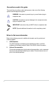
Conventions used in this guide To ensure that you perform certain tasks properly, take note of the following symbols used throughout this guide. WARNING: Information to prevent injury to yourself when trying to complete a task. CAUTION: Information to prevent damage to the components when trying to complete a task. IMPORTANT: Instructions that you MUST follow to complete a task. NOTE: Tips and additional information to aid in completing a task.
System package contents Check your BP5120 system package for the following items. Standard items 1. ASUS BP5120 Desktop PC with • ASUS Desktop x 1 • Mouse x 1 • Keyboard x 1 • AC power cable x 1 • LAN cable x 1 2. 3. Cables Accessories • Electric strip x 1 • Mouse pad x 1 4. Support CD x 1 and Recovery CD x 1 5. Installation Manual x 1 6. Warranty card x 1 If any of the items is damaged or missing, contact your retailer immediately. Optional items 1.
xii
This chapter gives a general description of the desktop PC. The chapter lists the system features including introduction on the front and rear panel, and internal components.
Chapter summary 1 1.1 Front panel..................................................................................... 1-1 1.2 Rear panel...................................................................................... 1-2 1.3 Connecting the keyboard and the mouse................................... 1-4 1.4 Connecting other peripheral devices.......................................... 1-4 1.5 Internal components.....................................................................
1.1 Front panel The ASUS BP5120 Desktop PC is made up of an ASUS motherboard, a power supply unit, a front panel, and a rear panel, etc. All of these components are integrated in a system casing elaborately designed by ASUS. The illustration below shows the front panel and the components on it. 1 x Storage card reader* SD MMC MS 1 x Headphone port 1 x Optical disk drive (ODD)* SMC CF MD 4 x USB 2.
1.2 Rear panel The system rear panel includes the power connector and several I/O ports that allow convenient connection of devices. The illustration below shows the rear panel and the components on it. 1 x Parallel port 4 x low profile Expansion slots* 1 x RJ-45 port 1 x PS/2 Mouse port 1 x Power connector LINE IN 15 MIC IN 1 x PS/2 Keyboard port 6-Channel audio ports 1 x COM port Voltage selector 1 x VGA port 4 x USB 2.
Selecting the voltage The system’s power supply unit has a 115V / 230V voltage selector switch located below the power connector. Use this switch to select the appropriate system input voltage according to the voltage supply in your area. If the voltage supply in your area is 100-127V, set the switch to 115V. If the voltage supply in your area is 200-240V, set the swith to 230V.
1.3 Connecting the keyboard and the mouse The ASUS BP5120 Desktop PC is equipped with a PS/2 keyboard and a USB mouse. Connect the PS/2 keyboard to the PS/2 keyboard port at the rear panel and the USB mouse to a USB port at the rear panel or front panel as you like. 1.4 Connecting other peripheral devices The ASUS BP5120 Desktop PC is equipped with a number of ports at the rear and the front panels where you can connect peripheral devices to the system. Refer to the illustration below for details.
1.5 Internal components The illustration below is the internal view of the system when you remove the top cover and the chassis support bracket. The installed components are labeled for your reference. Proceed to Chapter 2 for instructions on installing additional system components. 8 7 1 6 5 2 4 10 9 3 1. 5.25-inch empty optical drive bay 7. 2. Front panel cover (Removed) 3. Power supply unit 4. Expansion slots 5. ASUS motherboard 6. DIMM slots LGA775 socket (under the CPU fan) 8.
1- Chapter 1: System introduction
Chapter 2 SD MMC MS SMC CF MD Basic installation This chapter provides step-bystep instructions on how to install components in the system.
Chapter summary 2 2.1 Removing the covers.................................................................... 2-1 2.2 Preparation.................................................................................... 2-3 2.3 Installing a CPU............................................................................. 2-4 2.4 Installing a DIMM........................................................................... 2-8 2.5 Installing an expansion card................................................
2.1 Removing the covers 2.1.1 Removing the system cover The system panel is secured with four screws on the rear panel. Before you remove it, place the system horizontally. To remove the system panel: 1. On the rear panel, locate the four screws that secure the cover to the chassis. Use a Philips screw driver to remove the screws and keep them for later use. 2. Slightly push the cover toward the rear panel until the side tabs are disengaged from the chassis. 3. Lift the cover, then set aside.
2.1.2 Removing the front panel assembly To remove the front panel assembly: 1. Place the system vertically. Locate the front panel assembly hooks and pull the hooks outward to release the front panel assembly. 2. Swing the left edge of the front panel assembly outward and unhook the hinge-like tabs from the holes on the right side of the chassis to detach. 1 CF MD MS 1 SD MMC SMC 2 Do not use too much force when removing the front panel assembly.
2.2 Preparation Take note of the following precautions before you install components into the system. • Unplug the power cables before you touch any component in the system. • Use a grounded wrist strap or touch a safely grounded object or a metal object, such as the power supply case, before handling components to avoid damaging them due to static electricity. • Hold components by the edges to avoid touching the ICs on them.
2.3 Installing a CPU The motherboard comes with a surface mount LGA775 socket designed for the Intel® Core™2 Duo / Pentium® D/ Pentium® 4 / Celeron® D processors. 2.3.1 • Your boxed Intel® LGA775 processor package should come with installation instructions for the CPU, heatsink, and retention mechanism. If the instructions in this section do not match the CPU documentation, follow the latter. • Check your motherboard to ensure that the PnP cap is on the socket and the socket contacts are not bent.
2. Press the load lever with your thumb (A), then move it to the left (B) until it is released from the retention tab. To prevent damage to the socket pins, do not remove the PnP cap unless you are installing a CPU. 3. 4. Retention tab A B Load lever Lift the load lever in the direction of the arrow to a 135º angle. PnP cap Load plate 4B Lift the load plate with your thumb and forefinger to a 100º angle (4A), then push the PnP cap from the load plate window to remove (4B). 4A 3 5.
6. Apply Thermal Interface Material on the CPU before closing the load plate. DO NOT eat the Thermal Interface Material. If it gets into your eyes or touches your skin, ensure that you wash it off immediately, and seek professional medical help. 7. Close the load plate (A), then push the load lever (B) until it snaps into the retention tab. A B Intel® Hyper-Threading Technology 2- • The motherboard supports Intel® Pentium® 4 / Core™2 Duo LGA775 processors with Hyper-Threading Technology.
2.3.2 Installing the CPU fan and heatsink assembly The Intel LGA775 processor requires a specially designed heatsink and fan assembly to ensure optimum thermal condition and performance. ® Ensure that the Thermal Interface Material is properly applied to the CPU heatsink or CPU before you install the heatsink and fan assembly. To install the CPU heatsink and fan: 1. Place the heatsink on top of the installed CPU, ensuring that the four fasteners match the holes on the motherboard. 2.
3. When the fan and heatsink assembly is in place, connect the CPU fan cable to the connector on the motherboard. CPU_FAN CPU FAN PWM CPU FAN IN CPU FAN PWR GND R Rotation +12V GND P5KPL-VM CHA_FAN PWR_FAN Rotation +12V GND P5KPL-VM Fan Connectors Do not forget to connect the CPU fan connector! Hardware monitoring errors can occur if you fail to plug this connector. 2.4 Installing a DIMM To install a DDR2 DIMM: 2- 1. Locate the two DIMM slots on the motherboard. 2.
2.5 Installing an expansion card In the future, you may need to install expansion cards. The motherboard has two PCI slots, one PCI Express™ x1 slot, and one PCI Express™ x16 slot. The following subsections describe the slots and the expansion cards that they support. The system only supports low profile PCI, PCI Express x16, and PCI Express x1 cards. You can only install low profile expansion cards on this system. 2.5.
3. Align the card connector with the slot and press firmly until the card is completely seated on the slot. Replace the metal bracket lock. 4. Replace the metal bracket lock screw to secure the card. This system only supports low profile PCI, PCI Express x1, and PCI Express x16 cards. You can only install low profile expansion cards on this system.
2.5.2 Expansion cards PCI slots The PCI slots support cards such as LAN card, SCSI card, audio card, USB card and other cards that comply with PCI specifications. The figure shows a LAN card installed on a PCI slot. PCI Express x1 slot This motherboard supports PCI Express x1 network cards, SCSI cards and other cards that comply with PCI Express specifications. The figure shows a network card installed on a PCI Express x 1 slot.
2.5.
2.6 Installing a storage device Before you install a storage device to the system, remove the system cover and front panel assembly first. To remove the front panel assembly: 1 Swing the left edge of the front panel assembly outward and unhook the hinge-like tabs from the holes on the right side of the chassis to detach. 1 3. Place the system horizontally. Push the retention bracket locks (A) on both sides toward the front panel and disengage the supporting stand from the tenons (B).
2.6.1 Installing / Uninstalling a hard disk drive Installing a hard disk drive To install a hard disk drive: 1. Insert the hard disk to the 3.5 inch drive bay and carefully push the disk until its screw holes are aligned with the holes on the supporting stand. 3 2 3 1 2 2. Pull the retention brackets on both sides of the bay outward and align the hard disk to the retention brackets. 3. Press the retention bracket locks until the they are parallel to the hard disk. 4.
Uninstalling a hard disk drive To uninstall a hard disk drive: 1. Pull the retention bracket locks upward until they are vertical to the hard disk. 2. Push the retention brackets inward to disengage the hard disk. 3. Remove the hard disk from the back of the supporting stand. 1 3 2 1 2 Before you uninstalll a hard disk drive, be certain to unplug the cables.
2.6.2 Installing / Uninstalling a card reader / a floppy disk drive Installing a card reader To install a card reader: 1. Insert the card reader to the 3.5 inch drive bay and carefully push the card reader until its screw holes are aligned with the holes on the supporting stand. 2. Pull the retention brackets on both sides of the bay outward and align the hard disk to the retention brackets. 3. Press the retention bracket locks until they are parallel to the card reader. 4.
Uninstalling a card reader / floppy disk drive To uninstall a card reader: 1. Pull the retention bracket locks upward until they are vertical to the hard disk. 2. Push the retention brackets inward to disengage the card reader. 3. Remove the card reader from the back of the supporting stand. 1 2 1 2 3 Before you uninstall a card reader, be certain to unplug the cables.
2.6.3 Installing / Uninstalling an optical disk drive Installing an optical disk drive To install an optical disk drive: 1. Insert the optical disk to the 5.25 inch drive bay and carefully push the disk until its screws holes align with the holes on the supporting stand. 2. Pull the retention brackets on both sides of the bay outward and align the optical disk to the retention brackets. 3. Press the retention bracket locks until they are parallel to the hard disk.
Uninstalling an optical disk drive To uninstall an optical disk drive: 1. Pull the retention bracket locks upward until they are vertical to the hard disk. 2. Push the retention brackets inward to disengage the hard disk. 3. Remove the optical disk from the back of the supporting stand. 3 2 3 1 1 Before you uninstall an optical disk drive, be certain to unplug the cables.
2.7 Replacing the supporting stand and the covers After you have installed all the necessary components on the system, replace the supporting stand and the covers following the instructions in this section. 2.7.1 Replace the supporting stand To replace the supporting stand: 1. Insert the supporting stand into the tenons (A). 2. Push down the retention bracket locks (B) to secure the supporting stand to the system. B A B A 2.7.
2.7.3 Replacing the system cover To replace the system cover: 1. Place the system horizontally. Slightly push the cover toward the front panel until the side tabs are engaged into the chassis. 2. Secure the cover with the four screws that you removed earlier.
2-22 Chapter 2: Basic installation
Chapter 3 SD MMC MS SMC CF MD Getting started This chapter helps you to power up the system and install drivers and utilities from the support CD.
Chapter summary 3 3.1 Installing an operating system.................................................... 3-1 3.2 Powering your system.................................................................. 3-1 3.3 Support CD information............................................................... 3-2 3.4 Recovery CD..................................................................................
3.1 Installing an operating system This motherboard supports Windows® 2000 / XP / Vista operating systems (OS). Always install the latest OS version and corresponding updates to maximize the features of your hardware. When you start the system for the first time, the system automatically detects the built-in audio and graphics chips and attempts to install the drivers. Select NO when a window appears asking if you want to restart the system.
3.3 Support CD information The support CD that comes with the system package contains the drivers, software applications, and utilities that you can install to avail all system features. The contents of the support CD are subject to change at any time without notice. Visit the ASUS website at http://www.asus.com for updates. 3.3.1 Running the support CD Place the support CD to the optical drive. The CD automatically displays the Drivers menu if Autorun is enabled in your computer.
3.3.2 Drivers menu The drivers menu shows the available device drivers if the system detects installed devices. Install the necessary drivers to activate the devices. ASUS InstAll-Drivers Installation Wizard Installs the ASUS InstAll-Drivers Installation Wizard. Intel(R) Chipset Inf Update Program Installs the Intel® chipset Inf update program. Realtek Audio Driver Installs the Realtek® ALC883 audio driver and application.
3.3.3 Utilities menu The Utilities menu shows the applications and other software that the motherboard supports. Tap an item from the screen to install. ASUS InstAll-Installation Wizard for Utilities Installs all of the utilities through the Installation Wizard. ASUS Update Allows you to download the latest version of the BIOS from the ASUS website. Before using the ASUS Update, ensure that you have an Internet connection so that you can connect to the ASUS website.
3.3.4 Manuals menu The Support CD includes the manual of Realtek HD Audio. The manual is in PDF format. To open it, install the Adobe Acrobat Reader from the Utilities menu. 3.3.5 ASUS contact information Click the Contact tab to display the ASUS contact information.
3.3.6 Other information The icons on the top right corner of the screen give additional information on the motherboard and the contents of the support CD. Click an icon to display the specified information. Motherboard Info Displays the general specifications of the motherboard. Browse this CD Displays the support CD contents in graphical format.
Technical support Form Displays the ASUS Technical Support Request Form that you have to fill out when requesting technical support. Filelist Displays the contents of the support CD and a brief description of each in text format.
3.4 Recovery CD The ASUS PC Recovery CD assists you in reinstalling the OS and restoring it to its original working state. Before using the recovery CD, copy your data files to a USB device or to a network drive and make note of any customized configuration settings such as network settings. To recover a Windows XP OS: 1. Insert the first Recovery CD into the Optical Disk Drive. Press when the ASUS logo appears . Select the optical drive as the boot device. 2.
To recover a Windows Vista OS: 1. Turn on your ASUS Desktop PC and press F8 when the ASUS logo appears. 2. Insert the recovery CD into the optical drive when a Please select boot device menu appears. Select the optical drive as the boot device and then press Enter to continue. If you want to recover the system from the hidden partition, press F9 when the ASUS logo appears. Then follow the instructions 3-6 below. 3. After the system reboots, an ASUS Preload window appears. Press Next to continue. 4.
3-10 Chapter 3: Getting started