R C-P55T2D CPU Card USER'S MANUAL
USER'S NOTICE No part of this product, including the product and software may be reproduced, transmitted, transcribed, stored in a retrieval system, or translated into any language in any form by any means without the express written permission of ASUSTeK COMPUTER INC. (hereinafter referred to as ASUS) except documentation kept by the purchaser for backup purposes. Specifications are subject to change without notice.
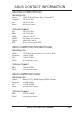
ASUS CONTACT INFORMATION ASUSTeK COMPUTER INC. Marketing Info: Address: Telephone: Fax: Email: 150 Li-Te Road, Peitou, Taipei, Taiwan, ROC 886-2-894-3447 886-2-894-3449 info@asus.com.tw Technical Support: Fax: BBS: Email: WWW: Gopher: FTP: 886-2-895-9254 886-2-896-4667 tsd@asus.com.tw http://www.asus.com.tw/ gopher.asus.com.tw ftp.asus.com.
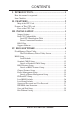
CONTENTS I. INTRODUCTION ........................................................ 1 How this manual is organized .......................................................... 1 Item Checklist .................................................................................. 1 II. FEATURES ................................................................. 2 Map of the CPU Card ................................................................. 2 Features of This CPU card ..........................................
CONTENTS V. DESKTOP MANAGEMENT ................................... 31 Desktop Management Interface (DMI) .......................................... 31 Introducing the DMI Configuration Utility ........................ 31 System Requirements ......................................................... 31 Using the DMI Configuration Utility ................................. 32 Notes: ..................................................................................
FCC & DOC COMPLIANCE Federal Communications Commission Statement This device complies with FCC Rules Part 15. Operation is subject to the following two conditions: • • This device may not cause harmful interference, and This device must accept any interference received, including interference that may cause undesired operation. This equipment has been tested and found to comply with the limits for a Class B digital device, pursuant to Part 15 of the FCC Rules.
I. INTRODUCTION I. INTRODUCTION (Manual / Checklist) How this manual is organized This manual is divided into the following sections: I. II. III. IV. V. Introduction: Features: Installation: BIOS Setup: DMI Utility: Manual information and checklist Information and specifications concerning this product Instructions on setting up the CPU card BIOS software setup information BIOS supported Desktop Management Interface Item Checklist Please check that your package is complete.
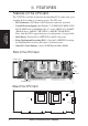
II. FEATURES Features of This CPU card II. FEATURES (Features) The C-P55T2D is carefully designed for the demanding PC user who wants great versatility in the assembly of a computer system. This CPU card: • PS/2 Connectors: PS/2 Mouse & PS/2 Keyboard connectors on bracket. • Versatile Processor Support: Intel Pentium® 75-233MHz (P55C-MMX™, P54C/ P54CS), IBM®/Cyrix® 6x86-PR166+ (Rev 2.7 or later), IBM®/Cyrix® 6x86MX™ (PR166 & above), AMD-K5™ (PR75-PR133), AMD-K6™ (PR166-PR233).
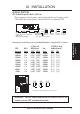
III. INSTALLATION Jumper Settings CPU to BUS Frequency Ratio (JP15, 16) These jumpers set the frequency ratio between the Internal frequency of the CPU and the External frequency (called the BUS Clock) within the CPU. 2 1 3/2 2 5/2 3 2.5x(5/2) 2.5x(5/2) 1.0x(1/1) 3.0x(3/1) 3.0x(3/1) 4.0x(4/1) JP15 JP16 Complete Names: Intel Pentium P54C, P55C-MMX AMD K5, K6 IBM/Cyrix 6X86, 6x86MX 1.5x(3/2) 2.0x(2/1) P54C/K5 3.5X(7/2) 2.0x(2/1) P55C/K6/MX 3.0x(3/1) 2.
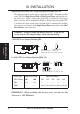
III. INSTALLATION Single/Dual Power Plane CPU Voltage Regulator Selections (JP1, 20) The following jumpers set the voltage supplied to the CPU. Determine whether your CPU has a Single Power Plane or Dual Power Planes and then the voltage that it uses. When a single power plane CPU is installed, the dual power plane selections will be automatically disabled. When a dual power plane CPU is installed, the single power plane selections will be automatically disabled.
III. INSTALLATION APIC Dual CPU Selection (JP14) This jumper turns on or off the multiprocessor operating system’s support for multiprocessors regardless of the number of processors installed in the system. For single processor operating systems (e.g. DOS, OS/2 Warp, Win3.1x, Win95, Nextstep): You can use one (or two) processor(s) and this “APIC Dual CPU Selection” jumper has no function (you may leave on default setting). For multiprocessor operating systems (e.g. WinNT, Unixware, SCO Unix MP, Solaris 2.
III. INSTALLATION Dual CPU Identification Table For 75-, 90, 100-, 120-, 133-, 150-, 166-, 200-MHz Pentium Processors III.
III. INSTALLATION Power Connection Procedures 1. After all jumpers and connections are made, close the system case cover. 2. Make sure that all switches are in the off position as marked by . 3. Connect the power supply cord into the power supply located on the back of your system case as instructed by your system user's manual. 4. Connect the power cord into an power outlet that is equipped by a surge protector. 5. You may then turn on your devices in the following order: a. Your monitor b.
IV. BIOS SOFTWARE Flash Memory Writer Utility 1. Enable "Boot Block Programming" jumper as shown in section III. 2. Make sure the system is running in real mode. This utility will not operate if the system is under protected mode or virtual mode. This means that you cannot reprogram the motherboard BIOS under the Windows environment or with any memory management software, including HIMEM.SYS.
IV. BIOS SOFTWARE 1. Save Current BIOS to File (Perform as soon as system is running) This option allows you to copy the contents of the Flash memory chip into a file in the \FLASH directory. This gives you a backup copy of the original motherboard BIOS in case you need to re-install it. In such cases where the data on the chip get lost or corrupted, you can reprogram the chip using this backup copy. 2. Update BIOS Main Block from File This option updates the BIOS from a file on the disk.
IV. BIOS SOFTWARE To select an option, type its corresponding number in the provided space and then press the key. Follow these procedure to update the PnP motherboard BIOS. 1. Download the new BIOS by selecting the second command option from the Advanced Features screen. The program displays a second screen prompting you for the name of the BIOS file. Type in the complete name of the file, including the file name extension, and then press the key.
IV. BIOS SOFTWARE 6. BIOS Setup The motherboard supports two programmable Flash ROM chips: 5 Volt and 12 Volt. Either of these memory chips can be updated when BIOS upgrades are released. Use the Flash Memory Writer utility to download the new BIOS file into the ROM chip as described in detail at the beginning of BIOS Software section IV. All computer motherboards provide a Setup utility program for specifying the system configuration and settings.
IV. BIOS SOFTWARE Load Defaults The “Load BIOS Defaults” option loads the minimized settings for troubleshooting. “Load Setup Defaults”, on the other hand, is for loading optimized defaults for regular use. Choosing defaults at this level, will modify all applicable settings. A section at the bottom of the above screen displays the control keys for this screen. Take note of these keys and their respective uses.
IV. BIOS SOFTWARE Details of Standard CMOS Setup: Date To set the date, highlight the “Date” field and then press the page up/page down or +/- keys to set the current date. Follow the month, day and year format. Valid values for month, day and year are: Month: Day: Year: 1 to 12 1 to 31 up to 2099 Time To set the time, highlight the “Time” field and then press the page up/page down or +/- keys to set the current time. Follow the hour, minute and second format.
IV. BIOS SOFTWARE For IDE hard disk drives, you can: • • • Use the Auto setting for detection during bootup (see below) Use the IDE HDD AUTO DETECTION in the main menu to automatically enter the drive specifications, or you can: Enter the specifications yourself manually by using the “User” option The entries for specifying the hard disk type include CYLS (number of cylinders), HEAD (number of read/write heads), PRECOMP (write precompensation), LANDZ (landing zone), SECTOR (number of sectors) and MODE.
IV. BIOS SOFTWARE Drive A, Drive B These fields record the types of floppy disk drives installed in your system. The available options for drives A and B are: 360KB, 5.25 in. 1.2MB, 5.25 in. 720KB, 3.5 in. 1.44MB, 3.5 in. 2.88MB, 3.5 in. None To enter the configuration value for a particular drive, highlight its corresponding field and then select the drive type using the left- or right-arrow key. Floppy 3 Mode Support This is the Japanese standard floppy drive. The standard stores 1.2MB in a 3.
IV. BIOS SOFTWARE BIOS Features Setup This “BIOS Features Setup” option consists of configuration entries that allow you to improve your system performance, or let you set up some system features according to your preference. Some entries here are required by the motherboard’s design to remain in their default settings. IV. BIOS (BIOS Features) A section at the lower right of the screen displays the control keys you can use. Take note of these keys and their respective uses.
IV. BIOS SOFTWARE Quick Power On Self Test This field speeds up the Power-On Self Test (POST) routine by skipping retesting a second, third, and fourth time. Setup default setting for this field is Enabled. A complete test of the system is done on each test. HDD Sequence SCSI/IDE First When using both SCSI and IDE hard disk drives, IDE is always the boot disk using drive letter C (default setting of IDE). This feature allows a SCSI hard disk drive to be the boot disk when set to SCSI.
IV. BIOS SOFTWARE PCI/VGA Palette Snoop Some display cards that are nonstandard VGA such as graphics accelerators or MPEG Video Cards may not show colors properly. The setting Enabled should correct this problem. Otherwise leave this on the setup default setting of Disabled. OS/2 Onboard Memory > 64M When using OS/2 operating systems with installed DRAM of greater than 64MB, you need to Enable this option otherwise leave this on the setup default of Disabled. MPS 1.4 Support MPS 1.
IV. BIOS SOFTWARE Chipset Features Setup This “Chipset Features Setup” option controls the configuration of the board’s chipset. Control keys for this screen are the same as for the previous screen. Auto Configuration The default setting of 60ns DRAM sets the optimal timings for items 2 through 9 for 60ns DRAM modules. If you are using 70ns DRAM modules, you must change this item to 70ns DRAM. See Section III (Installation) of the baseboard user’s manual for DRAM installation information. IV.
IV. BIOS SOFTWARE [DRAM and ECC] If all your DRAM modules have parity chips (e.g. 8 chips + 4 parity chips), they are considered 36bits. This motherboard sums the memory per bank and therefore two modules will give 72bits and the following will be displayed: If your DRAM modules do not have parity chips (e.g. 8 chips), they are considered 32bits and the following will be displayed instead: The default of Disabled for Memory parity SERR# (NMI) will not show memory errors on your monitor.
IV. BIOS SOFTWARE Onboard Parallel Port This field sets the address of the onboard parallel port connector. You can select either: 3BCH / IRQ 7, 378H / IRQ 7 (default), 278H / IRQ 5, Disabled. If you install an I/O card with a parallel port, ensure that there is no conflict in the address assignments. The PC can support up to three parallel ports as long as there are no conflicts for each port. Parallel Port Mode This field allows you to set the operation mode of the parallel port.
IV. BIOS SOFTWARE Power Management Setup This “Power Management Setup” option allows you to reduce power consumption. This feature turns off the video display and shuts down the hard disk after a period of inactivity. Details of Power Management Setup: IV. BIOS (Power Management) Power Management (User Define) This field acts as the master control for the power management modes.
IV. BIOS SOFTWARE Suspend Switch This field enables or disables the SMI connector on the motherboard. This connector connects to the lead from the Suspend switch mounted on the system case. Default setting for this field is Enable. Doze Speed (div by), Stdby Speed (div by) These two fields set the CPU speed during each mode. The number indicates what the normal CPU speed is divided by. PM Timers This section controls the time-out settings for the Power Management scheme.
IV. BIOS SOFTWARE PNP and PCI Setup This “PNP and PCI Setup” option configures the PCI bus slots. All PCI bus slots on the system use INTA#, thus all installed PCI cards must be set to this value. PNP OS Installed This field allows you to use a Plug-and-Play (PnP) operating system to configure the PCI bus slots instead of using the BIOS. Default setting is No. IV. BIOS (Plug & Play / PCI) Slot 1 (RIGHT) IRQ to Slot 4 (LEFT) IRQ These fields set how IRQ use is determined for each PCI slot.
IV. BIOS SOFTWARE DMA x Used By ISA These fields indicate whether or not the displayed DMA channel for each field is being used by a legacy (non-PnP) ISA card. Available options include: No/ICU and Yes. The first option, the default setting, indicates either that the displayed DMA channel is not used or an ICU is being used to determine if an ISA card is using that channel.
IV. BIOS SOFTWARE Load BIOS Defaults This “Load BIOS Defaults” option allows you to load the troubleshooting default values permanently stored in the BIOS ROM. These default settings are non-optimal and disable all high performance features. To load these default settings, highlight “Load BIOS Defaults” on the main screen and then press the key. The system displays a confirmation message on the screen. Press the key and then the key to confirm.
IV. BIOS SOFTWARE Supervisor Password and User Password IV. BIOS (Passwords) These two options set the system passwords. “Supervisor Password” sets a password that will be used to protect the system and the Setup utility; “User Password” sets a password that will be used exclusively on the system. By default, the system comes without any passwords. To specify a password, highlight the type you want and then press . A password prompt appears on the screen.
IV. BIOS SOFTWARE IDE HDD Auto Detection This “IDE HDD Auto Detection” option detects the parameters of an IDE hard disk drive, and automatically enters them into the Standard CMOS Setup screen. IV. BIOS (Hard Drive Detect) Up to four IDE drives can be detected, with parameters for each listed inside the box. To accept the optimal entries, press , otherwise select from the numbers displayed under the OPTIONS field (2, 1, 3 in this case); to skip to the next drive, press .
IV. BIOS SOFTWARE IMPORTANT: If your hard disk was already formatted on an older previous system, incorrect parameters may be detected. You will need to enter the correct parameters manually or use low-level format if you do not need the data stored on the hard drive. If the parameters listed differ from the ones used when the drive was formatted, the drive will not be readable. If the auto-detected parameters do not match the ones that should be used for your drive, do not accept them.
(This page was intentionally left blank) 30 ASUS C-P55T2D User’s Manual
V. DESKTOP MANAGEMENT Desktop Management Interface (DMI) Introducing the ASUS DMI Configuration Utility This motherboard supports DMI within the BIOS level and provides a DMI Configuration Utility to maintain the Management Information Format Database (MIFD). DMI is able to auto-detect and record information pertinent to a computer’s system such as the CPU type, CPU speed, and internal/external frequencies, and memory size.
V. DESKTOP MANAGEMENT Using the DMI Configuration Utility Edit DMI (or delete) Use the ← → (left-right) cursors to move the top menu items and the ↑↓ (up-down) cursor to move between the left hand menu items. The bottom of the screen will show the available keys for each screen. Press enter at the menu item to enter the right hand screen for editing. “Edit component” appears on top. The reversed color field is the current cursor position and the blue text are available for editing.
V. DESKTOP MANAGEMENT Save MIFD You can save the MIFD (normally only saved to flash ROM) to a file by entering the drive and path here. If you want to cancel save, you may press ESC and a message “Bad File Name” appears here to show it was not saved. Load MIFD You can load the disk file to memory by entering a drive and path and file name here. V. DMI (Using DMI Utility) Load BIOS Defaults You can load the BIOS defaults from a MIFD file and can clear all user modified and added data.
(This page was intentionally left blank) 34 ASUS C-P55T2D User’s Manual