® CUBX-L/CUBX-E Socket 370 ATX Motherboard USER’S MANUAL Special Features CUBX-L • UltraDMA/33 Support • 2 USB Ports CUBX-E • UltraDMA/100 Support • 5 USB Ports (2 standard, 3 upgradeable)
USER'S NOTICE No part of this manual, including the products and software described in it, may be reproduced, transmitted, transcribed, stored in a retrieval system, or translated into any language in any form or by any means, except documentation kept by the purchaser for backup purposes, without the express written permission of ASUSTeK COMPUTER INC. (“ASUS”).
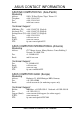
ASUS CONTACT INFORMATION ASUSTeK COMPUTER INC. (Asia-Pacific) Marketing Address: Telephone: Fax: Email: 150 Li-Te Road, Peitou, Taipei, Taiwan 112 +886-2-2894-3447 +886-2-2894-3449 info@asus.com.tw Technical Support MB/Others (Tel): +886-2-2890-7121 (English) Notebook (Tel): +886-2-2890-7122 (English) Desktop/Server (Tel):+886-2-2890-7123 (English) Fax: +886-2-2895-9254 Email: tsd@asus.com.tw WWW: www.asus.com.tw FTP: ftp.asus.com.
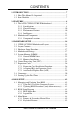
CONTENTS 1. INTRODUCTION .............................................................................. 7 1.1 How This Manual Is Organized .................................................. 7 1.2 Item Checklist ............................................................................. 7 2. FEATURES ......................................................................................... 8 2.1 The ASUS CUBX-L/CUBX-E Motherboard ............................. 8 2.1.1 Specifications .........................
CONTENTS 4.4 Advanced Menu ........................................................................ 54 4.4.1 Chip Configuration ........................................................ 58 4.4.2 I/O Device Configuration .............................................. 60 4.4.3 PCI Configuration ......................................................... 62 4.4.4 Shadow Configuration ................................................... 65 4.5 Power Menu .............................................................
FCC & DOC COMPLIANCE Federal Communications Commission Statement This device complies with FCC Rules Part 15. Operation is subject to the following two conditions: • • This device may not cause harmful interference, and This device must accept any interference received, including interference that may cause undesired operation. This equipment has been tested and found to comply with the limits for a Class B digital device, pursuant to Part 15 of the FCC Rules.
1. INTRODUCTION 1. INTRODUCTION Manual / Checklist 1.1 How This Manual Is Organized This manual is divided into the following sections: 1. 2. 3. 4. 5. 6. 7. INTRODUCTION FEATURES HARDWARE SETUP BIOS SETUP SOFTWARE SETUP SOFTWARE REFERENCE APPENDIX Manual information and checklist Production information and specifications Intructions on setting up the motherboard.
2. FEATURES 2.1 The ASUS CUBX-L/CUBX-E Motherboard The ASUS CUBX-L/CUBX-E is carefully designed for the demanding PC user who wants advanced features processed by the fastest CPU. 2.1.1 Specifications • 2. FEATURES Specifications FC-PGA FC-PGA PPGA • Intel AGPset: Features Intel’s 440BX AGPset with I/O subsystems and front-side bus (FSB) platform, which boosts the traditional 66MHz external bus speed to 100MHz.
• Multi-I/O: Provides two high-speed UART compatible serial ports and one parallel port with EPP and ECP capabilities. • UltraDMA/33 Bus Master IDE: Comes with an onboard PCI Bus Master IDE controller with two connectors that support four UltraDMA/33 IDE devices on two channels. Supports UltraDMA/33, PIO Modes 3 and 4, and Bus Master IDE DMA Mode 2, as well as Enhanced IDE devices, such as Tape Backup, CDROM, CD-R/RW, and LS-120 drives.
2. FEATURES 2.1.2 Special Features • 2. FEATURES Specifications • • • ACPI Ready: Advanced Configuration Power Interface (ACPI) provides more Energy Saving Features for operating systems that support OS Direct Power Management (OSPM) functionality. With these features implemented in the OS, PCs can be ready around the clock, yet satisfy all the energy saving standards. To fully utilize the benefits of ACPI, an ACPI-supported OS such as Windows 98 must be used.
2. FEATURES 2.1.4 Intelligence • • • • • Dual Function Power Button: Pushing the power button for less than 4 seconds when the system is in the working state places the system into one of two states: sleep mode or soft-off mode, depending on the BIOS or OS setting (see PWR Button < 4 Secs in 4.5 Power Menu). When the power button is pressed for more than 4 seconds, the system enters the soft-off mode regardless of the BIOS setting.
2. FEATURES 2.2 Motherboard Components See opposite page for locations. Location Processor Support Socket 370 for Pentium III/Celeron Processors ....................... 1 Feature Setting DIP Switches ................................................... 8 100/66MHz system bus (Frequency Multiples 2.0-8.0) 2. FEATURES MB Components Chipsets Intel 440BX AGPset ................................................................. 3 Multi-I/O Chipset .................................................................
2. FEATURES 2.2.1 Component Locations 1 2 3 4 5 4 2.
3. HARDWARE SETUP 3.1 CUBX-L/CUBX-E Motherboard Layout 21.8 cm (8.6 in) Promise ATA100 Row CR2032 3V Lithium Cell CMOS Power WOL_CON 6 7 LED1 DSW DIP Switches FLOPPY PCI2 SMB CHASIS CHA_FAN 2Mb Flash EEPROM (Programable BIOS) PCI3 PCI4 Intel PIIX4E PCIset CLRTC ASUS ASIC with Hardware Monitor WOR PCI5 JEN ISA1 ISA2 PANEL USB3A USB2 IDELED (Grayed components are only available on the CUBX-E motherboard.
3. HARDWARE SETUP 3.2 Layout Contents Motherboard Settings 1) JEN p. 18 JumperFree Mode Setting (Disable/Enable) 2) DSW 6 p. 20 AGP Bus Frequency Setting 3) DSW 5–10 p. 20 CPU External Frequency Selection 4) DSW 1-4 p. 21 CPU Core:BUS Frequency Multiple Selection 1) System Memory p.22 System Memory Support 2) DIMM1/2/3/4 p.22 DIMM Memory Module Support 3) Socket 370 p.25 CPU Support 4) PCI1/2/3/4/5 p.27 32-bit PCI Bus Expansion Slots 5) ISA1/ISA2 p.
3. HARDWARE SETUP 19) MSG.LED (PANEL) p. 38 System Message LED (2 pins) 20) SMI (PANEL) p. 38 System Management Interrupt Lead (2 pins) 21) PWR.SW (PANEL) p. 38 ATX / Soft-Off Switch Lead (2 pins) 22) RESET (PANEL) p. 38 Reset Switch Lead (2 pins) 23) ATXPWR p. 39 ATX Power Supply Connector (20 pins) 24) JTPWR p. 39 Power Supply Thermal Sensor Connector (2 pins) 3.
3. HARDWARE SETUP 3.3 Hardware Setup Procedure Before using your computer, you must complete the following steps: 1. Check Motherboard Settings 2. Install Memory Modules 3. Install the Central Processing Unit (CPU) 4. Install Expansion Cards 5. Connect Ribbon Cables, Panel Wires, and Power Supply 6. Setup the BIOS Software 3.4 Motherboard Settings This section explains in detail how to change your motherboard’s function settings through the use of switches and/or jumpers. 3.
3. HARDWARE SETUP Motherboard Features Settings (DIP Switches - DSW) The motherboard’s onboard functions are adjusted through the DIP switches. The white block represents the switch’s position. The example below shows all the switches in the OFF position. ® 1. Frequency Multiple 2. Frequency Multiple 3. Frequency Multiple 4. Frequency Multiple 5. (Reserved) 6. AGP Frequency Selection 7. Frequency Selection 8. Frequency Selection 9. Frequency Selection 10.
3. HARDWARE SETUP 2) AGP Bus Frequency Setting (DSW Switch 6) This option sets the frequency ratio between the AGP bus frequency and the DRAM (CPU bus) frequency. The default sets the AGP bus frequency to be 2/3 of the DRAM frequency. When the CPU/DRAM frequency is set to 66MHz, set this switch to [ON]. See the processor table on the next page. ON ON 1 2 3 4 5 6 7 8 9 10 1 2 3 4 5 6 7 8 9 10 DRAM Freq. x1 DRAM Freq. x2/3 3.
3. HARDWARE SETUP 3) CPU External Frequency Selection (DSW Switches 7-10) This option tells the clock generator what frequency to send to the CPU, DRAM, and the PCI bus. This allows the selection of the CPU’s External frequency (or BUS Clock). The BUS Clock multiplied by the Frequency Multiple equals the CPU’s Internal frequency (the advertised CPU speed). ON ON 1 2 3 4 5 6 7 8 9 10 1 2 3 4 5 6 7 8 9 10 1 2 3 4 5 6 7 8 9 10 75.0MHz 37.5MHz 83.0MHz 41.6MHz CPU/DRAM → 66.0MHz PCI BUS → 33.
3. HARDWARE SETUP 4) CPU Core:BUS Frequency Multiple (DSW Switches 1-4) This option sets the frequency multiple between the Internal frequency of the CPU and the CPU’s External frequency. These must be set in conjunction with the CPU Bus Frequency. DSW ON ON ON 1 2 3 4 5 6 7 8 9 10 1 2 3 4 5 6 7 8 9 10 2.0x(2/1) 2.5x(5/2) ON ON 3.0x(3/1) ON 1 2 3 4 5 6 7 8 9 10 1 2 3 4 5 6 7 8 9 10 3.5x(7/2) 4.0x(4/1) ON 1 2 3 4 5 6 7 8 9 10 4.
3. HARDWARE SETUP 3.5 System Memory (DIMM) NOTE: No hardware or BIOS setup is required after adding or removing memory. This motherboard uses only Dual Inline Memory Modules (DIMMs). Sockets are available for 3.3Volt (power level) unbuffered Synchronous Dynamic Random Access Memory (SDRAM). One side (with memory chips) of the DIMM takes up one row on the motherboard.
3. HARDWARE SETUP 3.5.2 Memory Installation WARNING! Make sure that you unplug your power supply when adding or removing memory modules or other system components. Failure to do so may cause severe damage to both your motherboard and expansion cards (see 3.3 Hardware Setup Procedure for more information). Insert the module(s) as shown. Because the number of pins are different on either side of the breaks, the module will only fit in the orientation shown.
3. HARDWARE SETUP (This page was intentionally left blank.) 3.
3. HARDWARE SETUP 3.6 Central Processing Unit (CPU) The motherboard provides a ZIF Socket 370. The CPU that came with the motherboard should have a fan attached to it to prevent overheating. If this is not the case, then purchase a fan before you turn on your system. WARNING! Be sure that there is sufficient air circulation across the processor’s heatsink by regularly checking that your CPU fan is working.
3. HARDWARE SETUP 3.7 Expansion Cards WARNING! Unplug your power supply when adding or removing expansion cards or other system components. Failure to do so may cause severe damage to both your motherboard and expansion cards. 3.7.1 Expansion Card Installation Procedure 3. H/W SETUP Expansion Cards 1. Read the documentation for your expansion card and make any necessary hardware or software settings for your expansion card, such as jumpers. 2.
3. HARDWARE SETUP 3.7.2 Assigning IRQs for Expansion Cards Some expansion cards need an IRQ to operate. Generally, an IRQ must be exclusively assigned to one use. In a standard design, there are 16 IRQs available but most of them are already in use, leaving 6 IRQs free for expansion cards. If your motherboard has PCI audio onboard, an additional IRQ will be used. If your motherboard also has MIDI enabled, another IRQ will be used, leaving 4 IRQs free.
3. HARDWARE SETUP 3. H/W SETUP DMA Channels Both ISA and PCI expansion cards may require IRQs. System IRQs are available to cards installed in the ISA expansion bus first, then any remaining IRQs are available to PCI cards. Currently, there are two types of ISA cards. The original ISA expansion card design, now referred to as legacy ISA cards, requires that you configure the card’s jumpers manually and then install it in any available slot on the ISA bus.
3. HARDWARE SETUP 3.7.3 Accelerated Graphics Port (AGP) 3. H/W SETUP Expansion Cards ® This motherboard provides an accelerated graphics port (AGP) slot to support a new generation of AGP graphics cards with ultra-high memory bandwidth. CUBX-L/CUBX-E Accelerated Graphics Port (AGP) WARNING! Make sure that you unplug your power supply when adding or removing an expansion card or other system components. Failure to do so may cause severe damage to both your motherboard and expansion cards (see 3.
3. HARDWARE SETUP 3.8 Connectors WARNING! Some pins are used for connectors or power sources. These are clearly distinguished from jumpers in the Motherboard Layout. Placing jumper caps over these connector pins will cause damage to your motherboard. IMPORTANT: Ribbon cables should always be connected with the red stripe to Pin 1 on the connectors. Pin 1 is usually on the side closest to the power connector on hard drives and CD-ROM drives, but may be on the opposite side on floppy disk drives.
3. HARDWARE SETUP 3) Universal Serial Bus Ports (Black two 4-pin USB) Two USB ports are available for connecting USB devices. USB 1 Universal Serial Bus (USB) 2 3. H/W SETUP Connectors 4) Parallel Port Connector (Burgundy 25-pin PRINTER) You can enable the parallel port and choose the IRQ through Onboard Parallel Port (see 4.4.2 I/O Device Configuration). NOTE: Serial printers must be connected to the serial port.
3. HARDWARE SETUP Chassis Signal GND ® +5VSB_MB 6) Chassis Intrusion Lead (4-1 pin CHASSIS) This requires an external detection mechanism such as a chassis intrusion monitor/sensor or microswitch. The sensor is triggered when a high level signal is sent to the Chassis Signal lead, which occurs when a panel switch or light detector is triggered. This function requires the optional ASUS CIDB chassis intrusion module to be installed (see 7. APPENDIX).
3. HARDWARE SETUP 8) IDE Connectors (40-1 pin PRIMARY / SECONDARY IDE) These connectors support the provided IDE hard disk ribbon cable. After connecting the single end to the board, connect the two plugs at the other end to your hard disk(s). If you install two hard disks, you must configure the second drive to Slave mode by setting its jumper accordingly. Please refer to your hard disk documentation for the jumper settings.
3. HARDWARE SETUP 9) Wake-On-LAN Connector (3-pin WOL_CON) This connector connects to a LAN card with a Wake-On-LAN output, such as the ASUS PCI-L101 Ethernet card (see 7. APPENDIX). The connector powers up the system when a wakeup packet or signal is received through the LAN card. IMPORTANT: This feature requires that Wake-On-LAN features are enabled (see 4.5.1 Power Up Control) and that your system has an ATX power supply with at least 720mA +5V standby power. ® WOL_CON +5VSB Ground PME 3.
3. HARDWARE SETUP 11) IDE Activity LED (2-pin IDELED) This connector supplies power to the cabinet’s IDE activity LED. Read and write activity by devices connected to the Primary or Secondary IDE connectors will cause the LED to light up. ® TIP: If the case-mounted LED does not light, try reversing the 2-pin plug. IDELED CUBX-L/CUBX-E IDE Activity LED 3.
3. HARDWARE SETUP 13) Infrared Module Connector (5-pin IR) This connector supports an optional wireless transmitting and receiving infrared module. This module mounts to a small opening on system cases that support this feature. You must also configure the setting through UART2 Use Infrared (see 4.4.2 I/O Device Configuration) to select whether UART2 is directed for use with COM2 or IrDA.
3. HARDWARE SETUP USB Power USBP2– USBP2+ GND NC 15) USB Headers (10-1 pin USB2, 5-1 pin USB3A) If the USB port connectors on the back panel are inadequate, two USB headers are available for three additional USB port connectors. Connect a 3-port USB connector set to these headers and mount it to an open slot on your chassis. 1 5 6 10 USB3A 1 3.
3. HARDWARE SETUP 16) ATX Power Supply Connector (20-pin block ATXPWR) This connector connects to an ATX power supply. The plug from the power supply will only insert in one orientation because of the different hole sizes. Find the proper orientation and push down firmly making sure that the pins are aligned. +5.0 Volts +5.0 Volts -5.0 Volts Ground Ground Ground Power Supply On Ground -12.0 Volts +3.
3. HARDWARE SETUP The following PANEL illustration is used for items 18–24. +5V Ground Ground SPKR PLED Keylock Ground Message LED SMI Lead ResetCon Ground +5 V MLED ExtSMI# Ground PWR_SW Ground ® +5 V * Requires an ATX power supply. Speaker Keyboard Lock Connector Power LED Reset SW ATX Power Switch* CUBX-L/CUBX-E System Panel Connections 3. H/W SETUP Connectors 18) System Power LED Lead (3-pin PWR.
3. HARDWARE SETUP (This page was intentionally left blank.) 3.
3. HARDWARE SETUP 3.9 Starting Up the First Time 1. After all connections are made, close the system case cover. 2. Be sure that all switches are off (in some systems, marked with ). 3. Connect the power supply cord into the power supply located on the back of your system case according to your system user’s manual. 4. Connect the power cord into a power outlet that is equipped with a surge protector. 3. H/W SETUP Powering Up 5. You may then turn on your devices in the following order: a. Your monitor b.
4. BIOS SETUP 4.1 Managing and Updating Your BIOS 4.1.1 Upon First Use of the Computer System It is recommended that you save a copy of the original motherboard BIOS along with a Flash Memory Writer utility (AFLASH.EXE) to a bootable floppy disk in case you need to reinstall the BIOS later. AFLASH.EXE is a Flash Memory Writer utility that updates the BIOS by uploading a new BIOS file to the programmable flash ROM on the motherboard. This file works only in DOS mode.
4. BIOS SETUP 5. Select 1. Save Current BIOS to File from the Main menu and press . The Save Current BIOS To File screen appears. 6. Type a filename and the path, for example, A:\XXX-XX.XXX and then press . 4.1.2 Updating BIOS Procedures (only when necessary) ASUS CUBX-L\CUBX-E User’s Manual 4. BIOS SETUP Updating BIOS 1. Download an updated ASUS BIOS file from the Internet (WWW or FTP) (see ASUS CONTACT INFORMATION on page 3 for details) and save to the disk you created earlier. 2.
4. BIOS SETUP 6. When prompted to confirm the BIOS update, press Y to start the update. 7. The utility starts to program the new BIOS information into the flash ROM. The boot block will be updated automatically only when necessary. This will minimize the chance of a failed updating. When the programming is finished, Flashed Successfully will be displayed. 4. BIOS SETUP Updating BIOS 8. Follow the onscreen instructions to continue.
4. BIOS SETUP 4.2 BIOS Setup Program This motherboard supports a programmable EEPROM that can be updated using the provided utility as described in 4.1 Managing and Updating Your BIOS. The utility is used if you are installing a motherboard, reconfiguring your system, or prompted to “Run Setup”. This section describes how to configure your system using this utility. Even if you are not prompted to use the Setup program, at some time in the future you may want to change the configuration of your computer.
4. BIOS SETUP 4.2.1 BIOS Menu Bar The top of the screen has a menu bar with the following selections: MAIN Use this menu to make changes to the basic system configuration. ADVANCED Use this menu to enable and make changes to the advanced features. POWER Use this menu to configure and enable Power Management features. BOOT Use this menu to configure the default system device used to locate and load the Operating System. EXIT Use this menu to exit the current menu or specify how to exit the Setup program.
4. BIOS SETUP General Help In addition to the Item Specific Help window, the BIOS setup program also provides a General Help screen. This screen can be called up from any menu by simply pressing or the + combination. The General Help screen lists the legend keys with their corresponding alternates and functions. Saving Changes and Exiting the Setup Program See 4.7 Exit Menu for detailed information on saving changes and exiting the setup program.
4. BIOS SETUP 4.3 Main Menu When the Setup program is accessed, the following screen appears: 4. BIOS SETUP Main Menu System Time [XX:XX:XX] Sets your system to the time that you specify (usually the current time). The format is hour, minute, second. Valid values for hour, minute and second are Hour: (00 to 23), Minute: (00 to 59), Second: (00 to 59). Use the or + keys to move between the hour, minute, and second fields.
4. BIOS SETUP 4.3.1 Primary & Secondary Master/Slave 4. BIOS SETUP Master/Slave Drives NOTE: Before attempting to configure a hard disk drive, make sure you have the configuration information supplied by the manufacturer of the drive. Incorrect settings may cause your system to not recognize the installed hard disk. To allow the BIOS to detect the drive type automatically, select [Auto]. Type [Auto] Select [Auto] to automatically detect an IDE hard disk drive.
4. BIOS SETUP IMPORTANT: If your hard disk was already formatted on an older previous system, incorrect parameters may be detected. You will need to enter the correct parameters manually or use low-level format if you do not need the data stored on the hard disk. If the parameters listed differ from the ones used when the disk was formatted, the disk will not be readable.
4. BIOS SETUP ASUS CUBX-L\CUBX-E User’s Manual 4. BIOS SETUP Master/Slave Drives Head This field configures the number of read/write heads. Refer to your drive documentation to determine the correct value to enter into this field. NOTE: To make changes to this field, the Type field must be set to [User Type HDD] and the Translation Method field must be set to [Manual]. Sector This field configures the number of sectors per track.
4. BIOS SETUP Other options for “Type:” are: [CD-ROM] - for IDE CD-ROM drives [LS-120] - for LS-120 compatible floppy disk drives [ZIP-100] - for ZIP-100 compatible disk drives [MO] - for IDE magneto optical disk drives [Other ATAPI Device] - for IDE devices not listed here After using the legend keys to make your selections on this sub-menu, press the key to exit back to the Main menu.
4. BIOS SETUP ® Intel PIIX4E PCIset 4. BIOS SETUP Main Menu Language [English] This allows selection of the BIOS’ displayed language. Configuration options: [English] Supervisor Password [Disabled], User Password [Disabled] This field allows you to set the password. To set the password, highlight the appropriate field and press . Type in a password and press . You can type up to eight alphanumeric characters. Symbols and other keys are ignored.
4. BIOS SETUP 4.4 Advanced Menu 4. BIOS SETUP Advanced Menu CPU Speed [Manual] When the motherboard is set to JumperFree mode (see 3.4 Motherboard Settings), this field allows you to select the internal speed of your CPU. Available options include multiples of 66 and 100. Select [Manual] if you want to make changes to the subsequent 2 fields. Note that selecting a frequency higher than the CPU manufacturer recommends may cause the system to hang or crash. See System Hangup later in this section.
4. BIOS SETUP CPU Vcore This field displays the core voltage supplied to the CPU. If you want to set it manually, always refer to the CPU documentation for the reasonable voltage range. Using Celeron processors Using Pentium III processors CPU Level 1 Cache, CPU Level 2 Cache [Enabled] These fields allow you to choose from the default of [Enabled] or choose [Disabled] to turn on or off the CPU’s Level 1 and Level 2 built-in cache.
4. BIOS SETUP Notes for JumperFree Mode CPU Upgrade/Reinstallation To ensure that your system can enter BIOS setup after the processor has been changed or reinstalled, your system will start up running at a bus speed of 66MHz and a fail-safe CPU speed (4x66MHz for the Intel Coppermine processor or 2x66MHz for non-Coppermine processors). It will then automatically take you to the Advanced menu with a popup menu of all the officially possible CPU speeds. 4.
4. BIOS SETUP System Hangup If your system crashes or hangs due to improper CPU settings, power OFF your system and restart. The system will start up in safe mode running at a bus speed of 66MHz and enter BIOS setup. 4. BIOS SETUP JumperFree Notes Cause for Hangup: Improper CPU Speed Cause for Hangup: Improper CPU Bus/PCI Freq.
4. BIOS SETUP 4.4.1 Chip Configuration (Scroll down to see more items as shown.) 4. BIOS SETUP Chip Configuration SDRAM Configuration [By SPD] This sets the optimal timings for items 2–5, depending on the memory modules that you are using. The default setting is [By SPD], which configures items 2–5 by reading the contents in the SPD (Serial Presence Detect) device.
4. BIOS SETUP SDRAM MA Wait State [Normal] This controls the leadoff clocks for CPU read cycles. Leave on default setting. Configuration options: [Fast] [Normal] [Slow] Snoop Ahead [Enabled] [Enabled] allows PCI streaming.
4. BIOS SETUP 4.4.2 I/O Device Configuration Onboard FDC Swap A & B [No Swap] This field allows you to reverse the hardware drive letter assignments of your floppy disk drives. Configuration options: [No Swap] [Swap AB] 4. BIOS SETUP I/O Device Config Floppy Disk Access Control [R/W] When set to [Read Only], this field protects files from being copied to floppy disks by allowing reads from the floppy disk drive but not writes. The setup default [R/W] allows both reads and writes.
4. BIOS SETUP Onboard Parallel Port [378H/IRQ7] This field sets the address of the onboard parallel port connector. If you disable this feature, Parallel Port Mode and ECP DMA Select configurations will not be available. Configuration options: [Disabled] [378H/ IRQ7] [278H/IRQ5] Parallel Port Mode [ECP+EPP] This field allows you to set the operation mode of the parallel port.
4. BIOS SETUP 4.4.3 PCI Configuration Slot 1 IRQ, Slot 2 IRQ, Slot 3/6 IRQ, Slot 4/5 IRQ [Auto] These fields set how IRQ use is determined for each PCI slot. The default setting for each field is [Auto], which uses auto-routing to determine IRQ use. Configuration options: [Auto] [NA] [3] [4] [5] [7] [9] [10] [11] [12] [14] [15] 4. BIOS SETUP PCI Configuration PCI/VGA Palette Snoop [Disabled] Some nonstandard VGA cards, such as graphics accelerators or MPEG Video Cards, may not show colors properly.
4. BIOS SETUP USB IRQ [Enabled] [Enabled] reserves an IRQ# for the USB to work. [Disabled] does not allow the USB to have an IRQ# and therefore prevents the USB from functioning. If you are not using any USB devices, you may set this feature to [Disabled] to save an extra IRQ# for expansion cards. Configuration options: [Disabled] [Enabled] Primary VGA BIOS [PCI Card] If your computer has both PCI and AGP VGA cards, this field allows you to select which of the cards will act as your primary graphics card.
4. BIOS SETUP PCI/PNP ISA DMA Resource Exclusion 4. BIOS SETUP PCI Configuration DMA x Used By ISA [No/ICU] These fields indicate whether or not the displayed DMA channel for each field is being used by a legacy (non-PnP) ISA card. The default setting indicates either that the displayed DMA channel is not used or an ICU is being used to determine if an ISA card is using that channel.
4. BIOS SETUP ISA MEM Block BASE [No/ICU] This field allows you to set the base address and block size of a legacy ISA card that uses any memory segment within the C800 and DFFF address range. If you have such a card and you are not using an ICU to specify its address range, select a base address from the six available options; the ISA MEM Block SIZE field will then appear for selecting the block size.
4. BIOS SETUP 4.5 Power Menu The Power menu allows you to reduce power consumption. This feature turns off the video display and shuts down the hard disk after a period of inactivity. 4. BIOS SETUP Power Menu Power Management [User Define] This option must be enabled to use any of the automatic power saving features. If this menu item is set to [Disabled], power management features will not function regardless of other field settings on this menu.
4. BIOS SETUP Video Off Option [Suspend -> Off ] This field determines when to activate the video off feature for monitor power management. Configuration options: [Always On] [Suspend -> Off] Video Off Method [DPMS OFF] This field defines the video off features. The DPMS (Display Power Management System) feature allows the BIOS to control the video display card if it supports the DPMS feature. [Blank Screen] only blanks the screen. (Use this for monitors without power management or “green” features.
4. BIOS SETUP 4.5.1 Power Up Control 4. BIOS SETUP Power Up Control AC PWR Loss Restart [Disabled] This allows you to set whether you want your system to reboot after the power has been interrupted. [Disabled] leaves your system off and [Enabled] reboots your system. [Previous State] sets your system back to the state it is before the power interruption.
4. BIOS SETUP PWR Up On PS2 KB/Mouse [Disabled] Select [Auto] if you wish to use your PS2 keyboard or PS2 mouse (by clicking on the left button) to power up your computer. The BIOS program will then determine whether your system has an ATX power supply that can supply at least 300mA on the +5VSB lead to support this feature. The default is set to [Disabled] because not all computers have the appropriate ATX power supply.
4. BIOS SETUP 4.5.2 Hardware Monitor MB Temperature, CPU Temperature [xxxC/xxxF] JTPWR Temperature [Ignore] The onboard hardware monitor is able to detect the MB (motherboard), CPU (for supported processors only), and power supply temperatures. Set to [Ignore] only if necessary. 4.
4. BIOS SETUP 4.6 Boot Menu Boot Sequence 4. BIOS SETUP Boot Menu The Boot menu allows you to select among the four possible types of boot devices listed using the up and down arrow keys. By using the <+> or key, you can promote devices and by using the <-> key, you can demote devices. Promotion or demotion of devices alters the priority which the system uses to search for a boot device on system power up.
4. BIOS SETUP Other Boot Device Select [INT18 Device (Network)] Configuration options: [Disabled] [SCSI Boot Device/Onboard ATA Boot Device] [INT18 Device (Network)] [LANDesk (R) Service Agent] IMPORTANT: The option [SCSI Boot Device/Onboard ATA Boot Device] is available only on the CUBX-E model. If [SCSI/Onboard ATA Boot Device] is selected, the system will boot from the UltraDMA/100/ 66 device first if Onboard ATA Device First is set to [Yes] (see 4.4.3 PCI Configuration).
4. BIOS SETUP 4.7 Exit Menu Once you have made all of your selections from the various menus in the Setup program, you should save your changes and exit Setup. Select Exit from the menu bar to display the following menu: 4. BIOS SETUP Exit Menu NOTE: Pressing does not exit this menu. You must select one of the options from this menu or from the legend bar to exit this menu.
4. BIOS SETUP Load Setup Defaults This option allows you to load the default values for each of the parameters on the Setup menus. When this option is selected or if is pressed, a confirmation is requested. Select [Yes] to load default values. You can now select Exit Saving Changes or make other changes before saving the values to the non-volatile RAM. Discard Changes This option allows you to discard the selections you made and restore the values you previously saved.
5. SOFTWARE SETUP 5.1 Install Operating System You should always use the latest operating system and updates when using new hardware to ensure full compliancy. You may use any version of Windows 98, but for Windows 95, you must use OSR 2.0 or later. For Windows NT 4.0, you must use Service Pack 3.0 or later. 5.2 Start Windows When you start Windows 98 for the first time after installing your motherboard, Windows will detect all plug-and play devices.
5. SOFTWARE SETUP 5.3.2 Support CD Installation Menu NOTE: The support CD contents are subject to change at any time without notice. To begin using your support CD disc, just insert it into your CD-ROM drive and the support CD installation menu should appear. If the menu does not appear, doubleclick or run E:\ASSETUP.EXE (assuming that your CD-ROM drive is drive E:). 5.
5. SOFTWARE SETUP • • • • • • • • • • Intel LDCM Administrator Setup (recommended): Installs software to monitor PC systems on the network within the same bridge address with the Client software installed. The administrator should install both Administrator and Client software. Intel LDCM Client Setup (recommended): Installs software to monitor the Client system. The LANDesk Client Manager must be installed to use the hardware manager features.
5. SOFTWARE SETUP (This page was intentionally left blank.) 5.
6. S/W REFERENCE ASUS PC Probe 6. SOFTWARE REFERENCE 6.1 ASUS PC Probe ASUS PC Probe is a convenient utility to continuously monitor your computer system’s vital components, such as fan rotations, voltages, and temperatures. It also has a utility that lets you review useful information about your computer, such as hard disk space, memory usage, and CPU type, CPU speed, and internal/external frequencies through the DMI Explorer. 6.1.
6. SOFTWARE REFERENCE 6. S/W REFERENCE ASUS PC Probe 6.1.2 Using ASUS PC Probe Monitoring Monitor Summary Shows a summary of the items being monitored. Temperature Monitor Shows the PC’s temperature (for supported processors only). Temperature Warning threshold adjustment (Move the slider up to increase the threshold level or down to decrease the threshold level) Fan Monitor Shows the PC’s fan rotation.
6. S/W REFERENCE ASUS PC Probe 6. SOFTWARE REFERENCE Settings Lets you set threshold levels and polling intervals or refresh times of the PC’s temperature, fan rotation, and voltages. CPU Cooling System Setup Lets you select when to enable software CPU cooling. When When CPU Overheated is selected, the CPU cooling system is enabled whenever the CPU temperature reaches the threshold value. History Lets you record the monitoring activity of a certain component of your PC for future reference.
6. SOFTWARE REFERENCE 6. S/W REFERENCE ASUS PC Probe Memory Shows the PC’s memory load, memory usage, and paging file usage. Device Summary Shows a summary of devices in your PC. DMI Explorer Shows information pertinent to the PC, such as CPU type, CPU speed, and internal/external frequencies, and memory size. Utility Lets you run programs outside of the ASUS Probe modules. To run a program, click Execute Program. NOTE: This feature is currently unavailable.
6. S/W REFERENCE ASUS PC Probe 6. SOFTWARE REFERENCE 6.1.3 ASUS PC Probe Task Bar Icon Right clicking the PC Probe icon will bring up a menu to open or exit ASUS PC Probe and pause or resume all system monitoring. When the ASUS PC Probe senses a problem with your PC, portions of the ASUS PC Probe icon changes to red, the PC speaker beeps, and the ASUS PC Probe monitor is displayed.
6. SOFTWARE REFERENCE 6. S/W REFERENCE ASUS Update 6.2 ASUS Update ASUS LiveUpdate is a utility that allows you to update your motherboard’s BIOS and drivers. The use of this utility requires that you are properly connected to the Internet through an Internet Service Provider (ISP). 1. Start ASUS Update Launch the utility from Start | Programs | ASUS Utility | ASUS Update Vx.xx. 2. Select an update method. 3.
7. APPENDIX 7. APPENDIX ASUS LAN Card 7.1 PCI-L101 Fast Ethernet Card LEDs LAN Activity Output Signal Intel Chipset RJ45 Wake on LAN Output Signal ASUS Motherboard type Other If you are using the ASUS PCI-L101 on an ASUS motherboard, leave the jumper on its defaut setting of “ASUS.” If you are using another brand of motherboard, set the jumper to “Other.” Connect the Wake on LAN (WOL) output signal to the motherboard’s WOL_CON in order to utilize the wake on LAN feature of the motherboard.
7. APPENDIX 7.1.1 Features 7. APPENDIX ASUS LAN Card • • • • • • • • • • • • Intel 82558 Ethernet LAN Controller (Fully integrated 10BASE-T/100BASE-TX) Wake-On-LAN Remote Control Function Supported PCI Bus Master Complies to PCI Local Bus Rev. 2.1 specifications Consists of MAC & PHY (10/100Mbps) interfaces Complies to IEEE 802.3 10BASE-T and IEEE 802.3u 100BASE-TX interfaces Fully supports 10BASE-T & 100BASE-TX operations through a single RJ45 port Supports 32-bit Bus Master Technology / PCI Rev. 2.
7. APPENDIX 7.2 ASUS CIDB Intrusion Detection Module Connectors to detect intrusion by chassis mounted micro switches 7. APPENDIX ASUS CIDB Module The optional ASUS CIDB is a module for providing audible intrusion alarm and logging for ASUS motherboards equipped with the chassis connector. The module detects a chassis intrusion by either light striking its photo sensor or by the closing or opening of a chassis-mounted momentary toggle switch.
7. APPENDIX 5. To stop the alarm from sounding, use the BIOS setup or momentarily place a jumper on (or short manually) the CLR jumper. Note that the jumper must be removed for the CIDB to work normally again. 6. If you have an updated BIOS with intrusion support, booting the computer after an intrusion may require a password if configured through BIOS. 7.2.2 Setting up the ASUS CIDB 7.
7. APPENDIX 7.3 Glossary Bus PCI AGP 1X AGP 2X AGP 4X Bus Frequency 33MHz 66MHz 66MHz 66MHz Bandwidth 33MHz 66MHz 133MHz 266MHz 7 . APPENDIX Glossary 1394 1394 is the IEEE designation for the high performance serial bus at 12.5, 25 or 50MBytes/sec speeds. This serial bus defines both a back plane physical layer and a point-to-point cable-connected virtual bus.
7. APPENDIX 7. APPENDIX Glossary Boot Boot means to start the computer operating system by loading it into system memory. When the manual instructs you to “boot” your system (or computer), it means to turn ON your computer. “Reboot” means to restart your computer. When using Windows 95 or later, selecting “Restart” from “Start | Shut Down...” will reboot your computer. Bus Master IDE PIO (Programmable I/O) IDE requires that the CPU be involved in IDE access and waiting for mechanical events.
7. APPENDIX ASUS CUBX-L/CUBX-E User’s Manual 7 . APPENDIX Glossary LPT Port (Line Printer Port) Logical device name reserved by DOS for the computer parallel ports. Each LPT port is configured to use a different IRQ and address assignment. MMX A set of 57 new instructions based on a technique called Single Instruction, Multiple Data (SIMD), which is built into the new Intel Pentium PP/MT (P55C) and Pentium II (Klamath) CPU as well as other x86-compatible microprocessors.
7. APPENDIX 7. APPENDIX Glossary ROM (Read Only Memory) ROM is nonvolatile memory used to store permanent programs (called firmware) used in certain computer components. Flash ROM (or EEPROM) can be reprogrammed with new programs (or BIOS). SCSI (Small Computer System Interface) High speed multi-threaded I/O interface defined by the X3T9.2 committee of the American National Standards Institute (ANSI) for connecting many peripheral devices.
INDEX Symbols 16-bit I/O Recovery Time 59 8-bit I/O Recovery Time 59 A AC PWR Loss Restart 68 Accelerated Graphics Port 29 AGP 29 ASUS PC Probe Using 79 ASUS Update Using 84 ATAPI CD-ROM 71 ATX Power Supply Connector 38 Automatic Power Up 69 B Beep Codes 41 BIOS Beep Codes 41 Managing 42 Updating 42 BIOS Beep Codes 41 BIOS Update 55 Boot Sequence 71 Boot Up Floppy Seek 72 Boot Up NumLock Status 52 Boot Virus Detection 72 C C8000-DFFFF Shadow 65 Central Processing Unit 25 Chassis Fan Speed 70 Chassis Intr
INDEX Hardware Monitor 70 Hardware Setup CPU Installation 25 Memory Installation 23 HDD Power Down 67 Head 51 Headers USB 37 Host Bus Fast Data Ready 59 I IDE Activity LED Lead 35 IDE Connectors 33 IDE Hard Drive 71 Installation CPU 25 Installed Memory 53 Interrupts Request Table 27 Standard Assignments 27 IRQ XX Used By ISA 63 ISA MEM Block BASE 65 K Keyboard Auto-Repeat Delay 52 Keyboard Auto-Repeat Rate 52 Keyboard Connector 30 Keyboard Lock Switch Lead 38 L Language 53 Leads Chassis Intrusion 32 IDE
INDEX Reset Switch Lead 38 S Save Changes 74 SDRAM CAS Latency 58 SDRAM Configuration 58 SDRAM RAS Precharge Time 58 SDRAM RAS to CAS Delay 58 Sector 51 Serial Port Connectors 31 Shadow Configuration 65 Slot 1 IRQ 62 Slot 2 IRQ 62 Slot 3/6 IRQ 62 Slot 4/5 IRQ 62 SMART Monitoring 51 SMBus Connector 36, 37 Snoop Ahead 59 Starting Up 41 Supervisor Password 53 Suspend Mode 67 Suspend-to-RAM Capability 67 SYMBIOS SCSI BIOS 62 System Date 48 System Hangup 57 System Message LED Lead 38 System Power LED Lead 38 Sy
INDEX (This page was intentionally left blank.
® Goes Mobile! L8400 Series Compact Professional Notebook PC • • • • • 14.1” TFT Color Display 450MHz to 700MHz+ 64MB to 192MB Memory 2X AGP 3D w/8MB VRAM 100MHz Processor Side Bus M8300/8200 Series Thin & Light Convertible Notebook PC • • • • 13.3” or 12.1” TFT Color Display 366MHz to 650MHz+ 64MB to 192MB Memory Supports Two Hard Drives L7300/7200 Series All-in-One Compact Notebook PC • 13.3” or 12.1” TFT Color Display • 366MHz to 650MHz+ • 64MB to 192MB Memory Visit www.asus.
® Barebone Servers Pentium® III PC100 ECC Ultra2 SCSI 5.25” Pentium® II Max. Memory Onboard Fixed Storage Support (GB) (Channels) Devices Hot-Swap Trays AP100 1 1 1 3 0 AP200 2 1 1 3 0 AP2000 2 1 1 4 3 or 5* AP2500 2 1 1 4 3 or 5* AP3000 2 Xeon™ 2 2 4 3 or 5* AP6000 2 1 1 4 8** AP7500 2 1 1 4 8** AP8000 2 Xeon™ 2 2 4 8** * ** Three 1.6-inch or five 1-inch SCA-2 SCSI hard drives Eight 1.
ASUS AR1000 RAID Sub-system with DA3000 SCSI-to-SCSI RAID Controller • • • • • • • • • • • • • • • • Supports 5x86 RAID processor and two 72-pin SIMM sockets for up to 128MB cache memory Supports three Ultra2 SCSI channels; up to 80MB/sec data transfer rate Supports multiple Host/Drive channel capacity Redundant controller capacity Supports non-RAID, RAID levels 0, 1, 0+1, 3, 5 On-line failure drive rebuilding Automatic rebuilding — supports local/global spare drive On-line expansion capacity Supports SAF-
® 8x DVD-ROM Drive • Industry-leading performance for even the most demanding applications • Maximum transfer rate: 8X DVD-ROM / 40X CD-ROM • High speed digital audio extraction • Supports UltraDMA/33 transfer mode • Complies with MPC3 standard • Supports Multi-Read function ® Ultra-Fast CD-ROM • • • • • Supports high speed CD-Audio playback Supports high speed digital audio extraction Supports UltraDMA/33 transfer mode Compatible with all CD formats Supports multi-read function (CD-R/CD-RW) Visit www