R P2B-D / P2B-DS Dual Pentium II Motherboards ® USER’S MANUAL Special Features • P2B-DS • Adaptec 7890 SCSI Chipset • Adaptec 3860 SCSI Transceiver
USER'S NOTICE No part of this manual, including the products and software described in it, may be reproduced, transmitted, transcribed, stored in a retrieval system, or translated into any language in any form or by any means, except documentation kept by the purchaser for backup purposes, without the express written permission of ASUSTeK COMPUTER INC. (“ASUS”).
ASUS CONTACT INFORMATION ASUSTeK COMPUTER INC. Marketing Address: Telephone: Fax: Email: 150 Li-Te Road, Peitou, Taipei, Taiwan 112 +886-2-2894-3447 +886-2-2894-3449 info@asus.com.tw Technical Support Fax: BBS: Email: WWW: FTP: +886-2-2895-9254 +886-2-2896-4667 tsd@asus.com.tw www.asus.com.tw ftp.asus.com.tw/pub/ASUS ASUS COMPUTER INTERNATIONAL Marketing Address: Fax: Email: 6737 Mowry Ave, Mowry Business Center, Building 2, Newark, CA 94560, USA +1-510-608-4555 info-usa@asus.com.
CONTENTS I. INTRODUCTION 7 How this Manual is Organized ........................................................... 7 Item Checklist ..................................................................................... 7 II. FEATURES 8 Features ............................................................................................... 8 The ASUS P2B-D/P2B-DS Motherboard ........................................... 9 III. INSTALLATION 10 ASUS P2B-D/P2B-DS Motherboard Layout ...............................
CONTENTS Power Management Setup ........................................................... 49 Details of Power Management Setup .................................... 49 PNP and PCI Setup ..................................................................... 52 Details of PNP and PCI Setup ............................................... 52 Load BIOS Defaults .................................................................... 54 Load Setup Defaults .............................................................
FCC & DOC COMPLIANCE Federal Communications Commission Statement This device complies with FCC Rules Part 15. Operation is subject to the following two conditions: • • This device may not cause harmful interference, and This device must accept any interference received, including interference that may cause undesired operation. This equipment has been tested and found to comply with the limits for a Class B digital device, pursuant to Part 15 of the FCC Rules.
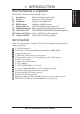
I. INTRODUCTION I. INTRODUCTION Manual / Checklist How this Manual is Organized This manual is divided into the following sections: I. Introduction II. Features III. Installation IV. BIOS Software V. Support Software VI. Desktop Management VII. ASUS LAN Card VIII. Adaptec SCSI Select IX. Adaptec EZ-SCSI Manual information and checklist Information and specifications Setting up the motherboard.
II. FEATURES Features The ASUS P2B-D/P2B-DS motherboards are carefully designed for the demanding PC user who wants advanced features processed by the fastest CPU. • • • II. FEATURES Specifications • • • • • • • • • • • • • 8 Multi-Speed: Supports Dual Intel Pentium® II processors from 233MHz to 450MHz. Intel AGPset: Features Intel’s 440BX AGPset with I/O subsystems and front-side bus (FSB) platform, which boosts the traditional 66-MHz internal bus speed to 100MHz.
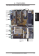
II. FEATURES The ASUS P2B-D/P2B-DS Motherboard SEC CPU Slots Intel 440BX AGPset 4 DIMM Sockets T: PS/2 Mouse B: PS/2 Keyboard II.
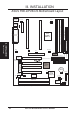
III. INSTALLATION FIR CIR JP4 1 Floppy Disk Drives DIMM Socket 0 (64 bit, 168 pin module) DIMM Socket 1 (64 bit, 168 pin module) Intel 440BX AGPset DIMM Socket 2 (64 bit, 168 pin module) COM 2 III.
III. INSTALLATION Jumpers 1) 2) 3) 4) 5) CLRTC KBPWR FS0, FS1, FS2 CF1, CF2, CF3, CF4 JP18 p. 13 p. 13 p. 14 p. 14 p. 15 Clear Real Time Clock (RTC) RAM Keyboard Power Up (Enable/Disable) CPU Bus Frequency CPU Core:Bus Frequency Multiple Chassis Intrusion Sensor Setting (Enable/Disable) p. 18 p. 19 p. 24 p. 25 p.
III. INSTALLATION Installation Steps Before using your computer, you must complete the following steps: 1. 2. 3. 4. 5. 6. Set Jumpers on the Motherboard Install System Memory Modules Install the Central Processing Unit (CPU) Install Expansion Cards Connect Ribbon Cables, Cabinet Wires, and Power Supply Setup the BIOS Software 1. Jumpers III. INSTALLATION Jumpers Several hardware settings are made through the use of jumper caps to connect jumper pins (JP) on the motherboard.
III. INSTALLATION Jumper Settings 1. Clear Real Time Clock (RTC) RAM (CLRTC) The CMOS RAM is powered by the onboard button cell battery. To clear the RTC data: (1) Turn off your computer and unplug its AC power, (2) Short the two solder points labeled CLRTC, (3) Turn on your computer, (4) Hold down during bootup and enter BIOS setup to re-enter user preferences. R Short the solder points to clear CMOS 1 1 III. INSTALLATION Jumpers P2B-D/DS Real Time Clock RAM (CLRTC) 2.
III. INSTALLATION 3. CPU Bus Frequency (FS0, FS1, FS2) This option tells the clock generator what frequency to send to the CPU, DRAM, and 440BX AGPset. This allows the selection of the CPU’s External frequency (or BUS Clock). The BUS Clock multiplied by the BUS Ratio equals the CPU’s Internal frequency (the advertised CPU speed). 4. CPU Core:BUS Frequency Multiple (BF0, BF1, BF2, BF3) This option sets the frequency ratio between the Internal frequency of the CPU and the CPU’s External frequency.
5. Chassis Intrusion Sensor Setting (JP18) (optional/reserved) This allows you to disable or enable the chassis intrusion sensor. Set to Enable if you want to use this function to monitor intrusion into your computer, for example, when the drive bay doors are opened. The default is set to Disable. JP18 JP18 R Disable (Default) Enable 1 1 III.
(This page was intentionally left blank.
III. INSTALLATION 2. System Memory (DIMM) This motherboard uses only Dual Inline Memory Modules (DIMMs). Three sockets are available for 3.3Volt (power level) unbuffered Synchronous Dynamic Random Access Memory (SDRAM) of either 8, 16, 32, 64, 128, or 256MB to form a memory size between 8MB and 1GB. One side (with memory chips) of the DIMM takes up one row on the motherboard.
III. INSTALLATION DIMM Memory Installation Procedures Insert the module(s) as shown. Because the number of pins is different on either side of the breaks, the module will only fit in the orientation as shown. DRAM SIMM modules have the same pin contacts on both sides. SDRAM DIMMs have different pin contacts on each side and therefore have a higher pin density. R 20 Pins 60 Pins 88 Pins 1 1 III. INSTALLATION System Memory Lock (FRONT) P2B-D/DS 168-Pin DIMM Memory Sockets The DIMMs must be 3.
III. INSTALLATION 3. Central Processing Unit (CPU) This motherboard provides two Single Edge Contact (SEC) slots for Pentium II processors packaged in SEC cartridges. Pentium II Processor You should check to see that you have the following items: Lock Holes Pentium II Retention Mechanism III.
III. INSTALLATION Installing the Pentium II Processor 1. Connect the Heat Sensor Cable to JP4/JP5 (optional): If you purchased the specially designed fan and thermal monitor heatsinks, you may connect the heat sensor cables to the motherboard’s CPU heat sensor connectors (JP4/JP5) now. NOTE: If you are installing only one processor, you may use JP5 to connect a heat sensor cable to monitor the power supply temperature to make sure that it is operating at a safe heat level.
III. INSTALLATION 3. Mount the Dual Processor Retention Mechanism: The dual processor retention mechanism is designed to fit into the SEC slots only one way. Be sure to align the notches in the retention mechanism with the small ribs (see preceding figure) on each side of the slots and that the mechanism is properly seated on the board. Then, screw the captive nuts in place. III. INSTALLATION CPU WARNING! Do not overtighten the captive nuts. Doing so could damage your motherboard.
III. INSTALLATION 5. Insert the SEC Cartridge: Push the SEC cartridge’s two locks inward until you hear a click (the preceding picture shows the locks in the outward position and inward in the picture below). With the heatsink facing the motherboard’s chipset, press the cartridge gently but firmly until it is fully inserted. (NOTE: The procedures shown here are for installing the AAVID heatsink with fan.) Push lock inward III.
III. INSTALLATION Recommended Heatsinks The recommended heatsinks for the Pentium II processor are those with three-pin fans that can be connected to the CPU fan connector on the motherboard. These heatsinks have the added benefits of proper heat dissipation and with the LM78 hardware monitor, the ability to monitor the fan’s RPM and use the alert function through the included LANDesk Client Manager (LDCM) software. IMPORTANT: The heatsinks must not be more than 2.8 cm (1.1 inch) thick. III.
III. INSTALLATION 4. Expansion Cards WARNING! Unplug your power supply when adding or removing expansion cards or other system components. Failure to do so may cause severe damage to both your motherboard and expansion cards. Expansion Card Installation Procedure III. INSTALLATION Expansion Cards 1. Read the documentation for your expansion card and make any necessary hardware or software settings for your expansion card, such as jumpers. 2.
III. INSTALLATION To simplify this process, this motherboard complies with the Plug and Play (PnP) specification, which was developed to allow automatic system configuration whenever a PnP-compliant card is added to the system. For PnP cards, IRQs are assigned automatically from those available. If the system has both legacy and PnP ISA cards installed, IRQs are assigned to PnP cards from those not used by legacy cards.
III. INSTALLATION 5. External Connectors WARNING! Some pins are used for connectors or power sources. Placing jumper caps over these will cause damage to your motherboard. IMPORTANT: Ribbon cables should always be connected with the red stripe on the Pin 1 side of the connector. The four corners of the connectors are labeled on the motherboard. Pin 1 is the side closest to the power connector on hard drives and floppy drives.
III. INSTALLATION 3. Parallel Printer Connector (25-pin Female) You can enable the parallel port and choose the IRQ through “Onboard Parallel Port” in Chipset Features Setup of the BIOS SOFTWARE. NOTE: Serial printers must be connected to the serial port. Parallel (Printer) Port (25-pin Female) III. INSTALLATION Connectors 4. Serial Port COM1 and COM2 Connectors (Two 9-pin Male) The two serial ports can be used for pointing devices or other serial devices. See “Onboard Serial Port...
III. INSTALLATION 6. Universal Serial BUS Ports 1 & 2 (Two 4-pin Female) Two USB ports are available for connecting USB devices. USB 1 Universal Serial Bus (USB) 2 III. INSTALLATION Connectors 7. Primary / Secondary IDE connectors (Two 40-1pin IDE) These connectors support the provided IDE hard disk ribbon cable. After connecting the single end to the board, connect the two plugs at the other end to your hard disk(s).
III. INSTALLATION 8. Hard Disk Activity LED (2-pin IDELED) This connector supplies power to the cabinet’s hard disk or IDE activity LED. Read and write activity by devices connected to the Primary or Secondary IDE connectors will cause the LED to light up. IDE_LED R 1 1 TIP: If the case-mounted LED does not light, try reversing the 2-pin plug. III. INSTALLATION Connectors P2B-D/DS IDE Activity LED 9.
III. INSTALLATION 10. IrDA-Compliant infrared module connector (5-pin IR) This connector supports the optional wireless transmitting and receiving infrared module. This module mounts to a small opening on system cases that support this feature. You must also configure the setting through “UART2 Use Infrared” in Chipset Features Setup to select whether UART2 is directed for use with COM2 or IrDA.
III. INSTALLATION 12. Wake-On-LAN (3-pin WOL) This connector connects to LAN cards with a Wake-On-LAN output, such as the AUS PCI-L101 (see section VII. ASUS LAN Card). The connector powers up the system when a wakeup packet or signal is received through the LAN card. IMPORTANT: This feature requires that the Wake-On-LAN Power Up Control is set to Enabled (see “Power Management Setup” under IV. BIOS SOFTWARE) and that your system has an ATX power supply with at least 720mA +5V standby power.
III. INSTALLATION III. INSTALLATION Connectors 14. LED Lead (MSG.LED) This indicates whether a message has been received from a fax/modem. The LED will remain lit when there is no signal and blink when there is data transfer or waiting in the inbox. This function requires ACPI OS and driver support. 15.
III. INSTALLATION 21. Fast (50 pins)/Wide (68 pins)/Ultra2 (68 pins) SCSI Connectors This motherboard has onboard 50-Pin Fast SCSI connector for 8-bit SCSI devices, 68-Pin Wide SCSI connector for 16-bit SCSI devices, and 68-Pin Ultra2 SCSI connector for 16-bit differential SCSI devices. 50-pin Fast SCSI II Connector 68-pin Wide SCSI Connector 68-pin Ultra2 SCSI Connector R 1 1 P2B-D/P2B-DS Onboard SCSI Connectors III.
III. INSTALLATION 22. SB-Link™ Connector (6-1 pin DMA_HEADER) (optional/reserved) Using Intel’s PC-PCI and serialized IRQ protocols found in this motherboard’s AGPset, this connector allows Sound Blaster 16 compatibility to AWE64D (Digital) or other PCI audio cards, enabling users to play Real-mode DOS games and multimedia applications. SB-Link acts as a bridge between the motherboard and the PCI audio card by providing the DMA and IRQ signals present in the ISA bus but not available on the PCI bus.
III. INSTALLATION Power Connection Procedures 1. After all jumpers and connections are made, close the system case cover. 2. Be sure that all switches are off (in some systems, marked with ). 3. Connect the power supply cord into the power supply located on the back of your system case according to your system user’s manual. 4. Connect the power cord into a power outlet that is equipped with a surge protector. III. INSTALLATION Power Connections 5.
IV. BIOS SOFTWARE Flash Memory Writer Utility This motherboard has an onboard SCSI BIOS and boot virus protection and therefore, requires a 2Mbit flash ROM. AFLASH.EXE: This is the Flash Memory Writer utility that updates the BIOS by uploading a new BIOS file to the 2Mbit programmable flash ROM chip on the motherboard. To determine the BIOS version of your motherboard, check the last four numbers of the code displayed on the upper left-hand corner of your screen during bootup.
IV. BIOS SOFTWARE 2. Update BIOS Including Boot Block and ESCD This option updates the boot block, the baseboard BIOS, and the ACPI extended system configuration data (ESCD) parameter block from a new BIOS file. See the next page for procedures on downloading an updated BIOS file. To update your current BIOS, type 2 at the Main Menu and then press . The Update BIOS Including Boot Block and ESCD screen appears. Type the filename of your new BIOS and the path, for example, A:\BX2I1002.
IV. BIOS SOFTWARE Managing and Updating Your Motherboard’s BIOS Upon First Use of the Computer System 1. Create a bootable system floppy disk by typing [FORMAT A:/S] from the DOS prompt without creating “AUTOEXEC.BAT” and “CONFIG.SYS” files. 2. Copy AFLASH.EXE to the just created boot disk. 3. Run AFLASH.EXE from this new disk and select option 1. Save Current BIOS to File. See 1. Save Current BIOS To File on the previous page for more details and the rest of the steps.
IV. BIOS SOFTWARE 6. BIOS Setup The motherboard supports two programmable Flash ROM chips: 5-Volt and 12Volt. Either of these memory chips can be updated when BIOS upgrades are released. Use the Flash Memory Writer utility to download the new BIOS file into the ROM chip as described in detail in this section. All computer motherboards provide a Setup utility program for specifying the system configuration and settings.
IV. BIOS SOFTWARE Load Defaults The “Load BIOS Defaults” option loads the minimum settings for troubleshooting. “Load Setup Defaults”, on the other hand, is for loading optimized defaults for regular use. Choosing defaults at this level, will modify all applicable settings. A section at the bottom of the above screen displays the control keys for this screen. Take note of these keys and their respective uses.
IV. BIOS SOFTWARE Time To set the time, highlight the “Time” field and then press either / or <+>/<–> to set the current time. Follow the hour, minute and second format. Valid values for hour, minute and second are: (Hour: (00 to 23), Minute: (00 to 59), Second: (00 to 59). NOTE: You can bypass the date and time prompts by creating an AUTOEXEC.BAT file. For information on how to create this file, please refer to the MS-DOS manual.
IV. BIOS SOFTWARE Auto detection of hard disks on bootup For each field: Primary Master, Primary Slave, Secondary Master, and Secondary Slave, you can select Auto under the TYPE and MODE fields. This will enable auto detection of your IDE hard disk during bootup. This will allow you to change your hard disks (with the power off) and then power on without having to reconfigure your hard disk type.
IV. BIOS SOFTWARE BIOS Features Setup The “BIOS Features Setup” option consists of configuration entries that allow you to improve your system performance, or let you set up some system features according to your preference. Some entries are required by the motherboard’s design to remain in their default settings. A section at the lower right of the screen displays the control keys you can use. Take note of these keys and their respective uses.
IV. BIOS SOFTWARE CPU Level 1 Cache / CPU Level 2 Cache (Enabled) These fields allow you to choose from the default of Enabled or choose Disabled to turn on or off the CPU’s Level 1 and Level 2 built-in cache. CPU Level 2 Cache ECC Check (Disabled) This function controls the ECC check capability in the CPU level 2 cache. BIOS Update (Enabled) This functions as an update loader integrated into the BIOS to supply the processor with the required data.
IV. BIOS SOFTWARE Security Option (System) When you specify a Supervisor Password and/or User Password (explained later in this section), the Security Option field determines when the system prompts for the password. The default setting is System, where the system prompts for the User Password every time you start your system. The other option is Setup, where the system goes through its startup routine unless the Setup utility is called, when the system prompts for the Supervisor Password.
IV. BIOS SOFTWARE Chipset Features Setup The “Chipset Features Setup” option controls the configuration of the board’s chipset. NOTE: SETUP Defaults are noted in parenthesis next to each function heading. Details of Chipset Features Setup IV. BIOS Chipset Features SDRAM Configuration (By SPD) This sets the optimal timings of settings for items 2–5, depending on the memory modules that you are using.
IV. BIOS SOFTWARE IV. BIOS Chipset Features 16-bit I/O Recovery Time (1 BUSCLK) / 8-bit I/O Recovery Time (1 BUSCLK) Timing for 16-bit and 8-bit ISA cards, respectively. Leave on default setting. Graphics Aperture Size (64MB) Memory-mapped, graphics data structures can reside in a Graphics Aperture. Leave on default setting. Video Memory Cache Mode (UC) USWC (uncacheable, speculative write combining) is a new cache technology for the video memory of the processor.
IV. BIOS SOFTWARE Onboard FDC Swap A & B (No Swap) This field allows you to reverse the hardware drive letter assignments of your floppy disk drives. Two options are available: No Swap and Swap AB. If you want to switch drive letter assignments through the onboard chipset, set this field to Swap AB. Onboard Serial Port 1 (3F8H/IRQ4) Settings are 3F8H/IRQ4, 2F8H/IRQ3, 3E8H/IRQ4, 2E8H/IRQ10, and Disabled for the onboard serial connector.
IV. BIOS SOFTWARE Power Management Setup This “Power Management Setup” option allows you to reduce power consumption. This feature turns off the video display and shuts down the hard disk after a period of inactivity. NOTE: SETUP Defaults are noted in parenthesis next to each function heading. Details of Power Management Setup IV. BIOS Power Management Power Management (User Define) This field acts as the master control for the power management modes.
IV. BIOS SOFTWARE Video Off Method (DPMS OFF) This field defines the video off features. The following options are available: DPMS OFF, DPMS Reduce ON, Blank Screen, V/H SYNC+Blank, DPMS Standby, and DPMS Suspend. The DPMS (Display Power Management System) features allow the BIOS to control the video display card if it supports the DPMS feature. Blank Screen only blanks the screen (use this for monitors without power management or “green” features.
IV. BIOS SOFTWARE PWR Up On Modem Act (Enabled) This allows either settings of Enabled or Disabled for powering up the computer (turns the ATX power supply on) when the modem receives a call while the computer is Soft-off. NOTE: The computer cannot receive or transmit data until the computer and applications are fully running, thus connection cannot be made on the first try.
IV. BIOS SOFTWARE PNP and PCI Setup The “PNP and PCI Setup” option configures the PCI bus slots. All PCI bus slots on the system use INTA#, thus all installed PCI cards must be set to this value. NOTE: SETUP Defaults are noted in parenthesis next to each function heading. Details of PNP and PCI Setup PNP OS Installed (No) This field allows you to use a Plug-and-Play (PnP) operating system to configure the PCI bus slots instead of using the BIOS.
IV. BIOS SOFTWARE DMA x Used By ISA (No/ICU) These fields indicate whether or not the displayed DMA channel for each field is being used by a legacy (non-PnP) ISA card. Available options include: No/ICU and Yes. The first option, the default setting, indicates either that the displayed DMA channel is not used or an ICU is being used to determine if an ISA card is using that channel.
IV. BIOS SOFTWARE Load BIOS Defaults The “Load BIOS Defaults” option allows you to load the troubleshooting default values permanently stored in the BIOS ROM. These default settings are non-optimal and disable all high performance features. To load these default settings, highlight “Load BIOS Defaults” on the main screen and then press . The system displays a confirmation message on the screen. Press and then to confirm. Press and then to abort.
IV. BIOS SOFTWARE Supervisor Password and User Password These two options set the system passwords. “Supervisor Password” sets a password that will be used to protect the system and the Setup utility; “User Password” sets a password that will be used exclusively on the system. By default, the system comes without any passwords. To specify a password, highlight the type you want and then press . A password prompt appears on the screen.
IV. BIOS SOFTWARE IDE HDD Auto Detection This “IDE HDD Auto Detection” option detects the parameters of an IDE hard disk drive, and automatically enters them into the Standard CMOS Setup screen. IV. BIOS Hard Disk Detect Up to four IDE drives can be detected, with parameters for each listed inside the box. To accept the optimal entries, press or else select from the numbers displayed under the OPTIONS field (2, 1, 3 in this case); to skip to the next drive, press .
IV. BIOS SOFTWARE IMPORTANT: If your hard disk was already formatted on an older previous system, incorrect parameters may be detected. You will need to enter the correct parameters manually or use low-level format if you do not need the data stored on the hard disk. If the parameters listed differ from the ones used when the disk was formatted, the disk will not be readable. If the auto-detected parameters do not match the ones that should be used for your disk, do not accept them.
V. SUPPORT SOFTWARE ASUS Smart Motherboard Support CD Inserting the support CD brings up a selection menu described as follows: NOTE: CD version and contents are subject to change at any time without notice. • ASUS PC Probe Utility: Installs a simple software to monitor your computer’s fan, temperature, and voltages. NOTE: This utility will not run with LDCM installed. V. SUPPORT S/W ASUS Smart Motherbaord • LDCM Local Setup: Installs software to monitor the local system.
VI. DESKTOP MANAGEMENT VI. DMI Using DMI Utility Desktop Management Interface (DMI) Introducing the ASUS DMI Configuration Utility This motherboard supports DMI within the BIOS level and provides a DMI Configuration Utility to maintain the Management Information Format Database (MIFD). DMI is able to auto-detect and record information pertinent to a computer’s system such as the CPU type, CPU speed, and internal/external frequencies, and memory size.
VI. DESKTOP MANAGEMENT VI. DMI Using DMI Utility Using the ASUS DMI Configuration Utility NOTE: The following screen displays are provided as examples only and may not reflect the screen contents on your system. Edit DMI (or delete) Use the ←→ (left-right) cursors to move between the top menu items and the ↑↓ (up-down) cursors to move between the left hand menu items. The bottom of the screen will show the available keys for each screen.
VI. DESKTOP MANAGEMENT VI. DMI Using DMI Utility Save MIFD You can save the MIFD (normally only saved to flash ROM) to a file by entering the drive and path here. If you want to cancel save, you may press ESC and a message “Bad File Name” appears here to show it was not saved. Load MIFD You can load the disk file to memory by entering a drive and path and file name here. Load BIOS Defaults You can load the BIOS defaults from a MIFD file and can clear all user modified and added data.
(This page was intentionally left blank.
VII. ASUS LAN Card VII. ASUS LAN Card PCI-L101 LAN Card ASUS PCI-L101 Fast Ethernet Card LEDs LAN Activity Output Signal Intel Chipset RJ45 Wake on LAN Output Signal ASUS Motherboard type Other If you are using the ASUS PCI-L101 on an ASUS motherboard, leave the jumper on its defaut setting of “ASUS.” If you are using another brand of motherboard, set the jumper to “Other.
VII. ASUS LAN Card Features VII. ASUS LAN Card Features • • • • • • • • • • • • Intel 82558 Ethernet LAN Controller (Fully integrated 10BASE-T/100BASE-TX) Wake-On-LAN Remote Control Function Supported PCI Bus Master Complies to PCI Local Bus Rev. 2.1 specifications Consists of MAC & PHY (10/100Mbps) interfaces Complies to IEEE 802.3 10BASE-T and IEEE 802.3u 100BASE-TX interfaces Fully supports 10BASE-T & 100BASE-TX operations through a single RJ45 port Supports 32-bit Bus Master Technology / PCI Rev. 2.
VIII. ADAPTEC SCSI SELECT Configuring the SCSI Adapter Access the SCSI BIOS by holding down both CTRL and A keys when you see the BIOS banner message listing the driver name and the attached devices. For example: Adaptec AIC-7890 SCSI BIOS Build 20107 (c) 1998 Adaptec, Inc. All Rights Reserved. <<< Press for SCSISelect(TM) Utility! >>> The SCSISelect screen will come up. Instructions on how to move the cursor and select options are listed on the bottom of the program windows.
(This page was intentionally left blank.
IX. ADAPTEC EZ-SCSI Welcome to Adaptec EZSCSIVI, ADAPTEC EZ-SCSI UTILITY 4.03. Adaptec EZSCSI gives you what you need to use DOS, Windows®3.1x, or Windows for Workgroups3.1x. Note: The ADAPTEC EZ-SCSI UTILITY does not provide drivers for Windows®95 and WindowsNT™. Quick Start Instructions First, install SCSI devices (see the hardware documentation for details). Then follow the instructions for your operating system software in one of the following sections.
IX. ADAPTEC EZ-SCSI Troubleshooting Tips SCSI Device Troubleshooting Review this checklist if your newly-installed SCSI disk drives, CDROM drives, and other devices do not seem to work properly: • Be sure that termination is correctly set for all devices on the SCSI bus, as • • • • described in your host adapter documentation. Be sure there are no hardware conflicts such as devices in your computer trying to use the same interrupts (IRQs) or DMA channels.
IX. ADAPTEC EZ-SCSI If the name of your SCSI chipset does not appear, you may be able to find its miniport driver on the Windows95 CD-ROM. Follow these steps: 1 Place the Windows95 CD-ROM in your CDROM drive and run the Add New Hardware wizard. 2 Select No on the second screen, and select SCSI controllers on the next screen. 3 Click on the Have Disk button, then click the Browse button. 4 Look in the \drivers\storage directory of the CDROM and select the name of your SCSI host adapter if it appears. IX.
IX. ADAPTEC EZ-SCSI If I am running under Windows95, do I need lines for the Adaptec real mode ASPI drivers and mscdex in my CONFIG.SYS and AUTOEXEC.BAT files? Usually, you do not need to use these real mode ASPI drivers, because the new Windows miniport drivers support most SCSI host adapters and SCSI devices.
IX. ADAPTEC EZ-SCSI Information for DOS/Windows 3.1x Users The following information may be useful if you install Adaptec EZSCSI on a computer running DOS, Windows 3.1x, or Windows for Workgroups3.1x. NOTE: The Windows95/WindowsNT Troubleshooting section on page 6 describes a few situations when you may need to use the DOS/Windows3.1x drivers and ASPI managers under Windows95 or WindowsNT. DOS and Windows3.
IX. ADAPTEC EZ-SCSI DOS Formatting Utilities Adaptec EZSCSI includes several DOS-based formatting utilities: Low-level Formatter (scsifmt) Use the DOS-based scsifmt utility for low-level formatting of SCSI hard disk drives, removable media, Floptical® drives, and magneto-optical drives. You can also use it to scan a disk device for surface defects before you store data on it. Run scsifmt from the DOS prompt, not from the Windows MSDOS prompt.
IX. ADAPTEC EZ-SCSI Formatter and Partitioner (afdisk) Use the DOS-based afdisk utility to partition and format SCSI hard disk drives, Floptical drives, and magneto-optical drives. You can also use afdisk to remove DOS and non-DOS partitions from a disk drive and to format removable media in standard hard disk format, OS/2 floppy format, or DOS V (Japanese) format.
IX. ADAPTEC EZ-SCSI 3. To create a new partition on the disk device, press Ins. A screen similar to this appears: Adaptec SCSI Disk Setup Program v3.33 Select SCSI Device to Partition HA #0 - Target 0 HA #0 - Target 4 Type Start End Megs QUANTUM LP105S 910109405 IOMEGA BETA90 Logical Drive Info 64 32 85 512 head sectors/track cylinders bytes/sector Create a DOS Partition Start Cylinder: End Cylinder: 85 megabytes 2AEEFh blocks 0 84 Create, Delete, Help, Exit IX.