P4B-M User Guide Motherboard ®
E863 Checklist Revised Edition 1.02 (August 2001) Copyright © 2001 ASUSTeK COMPUTER INC. All Rights Reserved. No part of this manual, including the products and software described in it, may be reproduced, transmitted, transcribed, stored in a retrieval system, or translated into any language in any form or by any means, except documentation kept by the purchaser for backup purposes, without the express written permission of ASUSTeK COMPUTER INC. (“ASUS”).
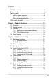
Contents Features FCC/CDC statements ..................................................................... vi Safety information .......................................................................... vii About this guide ............................................................................ viii How this guide is organized .................................................. viii Conventions used in this guide ............................................... ix Where to find more information .......
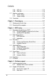
Contents Safeguards 2.7 2.8 2.6.4 AGP slot ............................................................... 2.6.5 CNR slot ............................................................... Switches and jumpers ....................................................... 2.7.1 Switch settings ...................................................... 2.7.2 Jumper settings .................................................... Connectors .......................................................................
Contents 5.3 5.2.3 Software menu ....................................................... 5.2.4 Drivers menu .......................................................... 5.2.5 DOS Utilities menu ................................................. 5.2.6 ASUS Contact Information ...................................... 5.2.7 Other information .................................................... Software information ........................................................... 5.3.1 ASUS Update ......................
FCC/CDC statements Federal Communications Commission Statement This device complies with FCC Rules Part 15. Operation is subject to the following two conditions: • • This device may not cause harmful interference, and This device must accept any interference received including interference that may cause undesired operation. This equipment has been tested and found to comply with the limits for a Class B digital device, pursuant to Part 15 of the FCC Rules.
Safet y information Electrical safety • To prevent electrical shock hazard, disconnect the power cable from the electrical outlet before relocating the system. • When adding or removing devices to or from the system, ensure that the power cables for the devices are unplugged before the signal cables are connected. If possible, disconnect all power cables from the existing system before you add a device.
About this guide This user guide contains the information you need when installing the ASUS P4B-M motherboard. How this guide is organized This manual contains the following parts: • • • • • • • viii Chapter 1: Product introduction This chapter describes the features of the P4B-M motherboard. It includes brief descriptions of the special attributes of the motherboard and the new technology it supports.
Conventions used in this guide To make sure that you perform certain tasks properly, take note of the following symbols used throughout this manual. WARNING: Information to prevent injury to yourself when trying to complete a task. CAUTION: Information to prevent damage to the components when trying to complete a task. IMPORTANT: Information that you MUST follow to complete a task. NOTE: Tips and additional information to aid in completing a task.
ASUS contact information ASUSTeK COMPUTER INC. (Asia-Pacific) Marketing Address: Telephone: Fax: Email: 150 Li-Te Road, Peitou, Taipei, Taiwan 112 +886-2-2894-3447 +886-2-2894-3449 info@asus.com.tw Technical Support Tel (English): Tel (Chinese): Fax: Email: Newsgroup: WWW: FTP: +886-2-2890-7123 +886-2-2890-7113 +886-2-2890-7698 tsd@asus.com.tw cscnews.asus.com.tw www.asus.com.tw ftp.asus.com.
Chapter 1 This chapter describes the features of the P4B-M motherboard. It includes brief explanations of the special attributes of the motherboard and the new technology it supports.
ASUS P4B-M motherboard
1.1 Welcome! Thank you for buying the ASUS® P4B-M motherboard! The ASUS P4B-M motherboard delivers a host of new features and latest technology making it another standout in the long line of ASUS quality motherboards! The P4B-M incorporates the Intel® Pentium® 4 Processor in 478-pin package/Northwood Processor coupled with the Intel® 845 (Brookdale) chipset to set a new benchmark for an effective desktop platform solution.
1.3 Over view Before you install the P4B-M motherboard, take some time to familiarize yourself with its physical configuration and available features. This will facilitate the motherboard installation and future upgrades. A sufficient knowledge of the motherboard specifications will also help you avoid mistakes that may damage the board and its components. This section presents the motherboard components and points out their specific locations. A brief description of each component follows.
1 CPU socket. A 478-pin surface mount, Zero Insertion Force (ZIF) socket called mPGA478 B. This socket accommodates the Intel® Pentium® 4 478/Northwood Processor with 400MHz system bus. 2 North bridge controller. This controller called the Intel Memory Controller Hub (MCH) is one of the two major components of the Intel 845 (Brookdale) chipset. The MCH along with the south bridge Intel I/O Controller Hub 2 (ICH2) are interconnected through the Intel proprietary Hub interface.
1-4 10 South bridge controller. Referred to as the Intel I/O Controller Hub 2 (ICH2) of the Intel 845 chipset, this controller provides the I/O subsystem that allows access to the rest of the system. The ICH2 integrates I/O functions such as system bus interface, Ultra ATA/100, Low Pin Count (LPC) interface, Universal Serial Bus (USB) 1.1 interface, PCI interface, and CNR interface. 11 ASUS ASIC.
22 ATX 12V connector. This power connector connects the 4-pin 12V plug from the ATX 12V power supply. 23 Serial ports. These two 9-pin COM1/COM2 ports are for pointing devices or other serial devices. 24 Parallel port. This 25-pin port connects a parallel printer, a scanner, or other devices. 25 USB ports. These two 4-pin Universal Serial Bus (USB) ports are available for connecting USB devices such as a mouse and PDA. 26 RJ-45 port.
1.4 Special features Latest processor technology The P4B-M motherboard supports the latest Intel Pentium 4 478/ Northwood Processor, also known as P4, via a 478-pin surface mount ZIF socket. The Pentium 4 processor utlizes the advanced 0.18 micron processor core in FC-PGA2 package for a 2.0GHz frequency, while the Northwood processor uses the 0.13 micron processor core with 512KB L2 cache for up to a speedy 2.4GHz frequency. The P4 offers optimized performance for audio, video, and Internet applications.
Chapter 2 This chapter describes the hardware setup procedures that you have to perform when installing system components. It includes details on the switches, jumpers, and connectors on the motherboard.
ASUS P4B-M motherboard
2.1 Motherboard installation Before you install the motherboard, study the configuration of your chassis to ensure that the motherboard fits into it. The P4B-M uses the micro-ATX form factor that measures 9.6 inches x 9.6 inches, a standard fit for most chassis. Make sure to unplug the power cord before installing or removing the motherboard. Failure to do so may cause you physical injury and damage motherboard components. 2.1.
2.2 Motherboard layout 24.4cm (9.60in) PS/2KBMS KBPWR T: Mouse B: Keyboard CPU_FAN 4 5 LAN_EN BCS1 BCS2 AUX Accelerated Graphics Port (AGP) INT_LINEIN PCI1 CD SPDIF_C MIC HPHONE SERIRQ_CON CR2032 3V Lithium Cell CMOS Power PCI2 Intel I/O Controller Hub (ICH2) FLOPPY P4B-M 2Mbit Firmware Hub CLEAR CMOS BUZZER ® MODEM C-Media CMI8738 6CH Audio Controller CNR_SLOT Figure 2-2 ASUS ASIC PCI3 LED1 24.4cm (9.
2.3 Before you proceed Take note of the following precautions before you install motherboard components or change any motherboard settings. 1. Unplug the power cord from the wall socket before touching any component. 2. Use a grounded wrist strap or touch a safely grounded object or to a metal object, such as the power supply case, before handling components to avoid damaging them due to static electricity. 3. Hold components by the edges and do not to touch the ICs on them. 4.
2.4 Central Processing Unit (CPU) 2.4.1 Overview The motherboard comes with a surface mount 478-pin Zero Insertion Force (ZIF) socket. This socket is specifically designed for the Intel® Pentium® 4 478/Northwood Processor. The Intel Pentium 4 Processor in the 478-pin package uses the Flip-Chip Pin Grid Array 2 (FC-PGA2) package technology, and includes the Intel® NetBurst™ micro-architecture.
2.4.2 Installing the CPU Follow these steps to install a CPU. 1. Locate the 478-pin ZIF socket on the motherboard. Figure 2-5 Intel 478-pin ZIF Socket 2. Unlock the socket by pressing the lever sideways, then lift it up to a 90°-100° angle. Socket Lever 90 - 100 Figure 2-6 CPU Socket Lever at 90° -100° Angle Make sure that the socket lever is lifted up to 90°-100° angle, otherwise the CPU does not fit in completely.
3. Position the CPU above the socket such that its marked corner matches the base of the socket lever. 4. Carefully insert the CPU into the socket until it fits in place. The CPU fits only in one correct orientation. DO NOT force the CPU into the socket to prevent bending the pins and damaging the CPU! Gold Mark Figure 2-7 Installing the CPU 5. When the CPU is in place, press it firmly on the socket while you push down the socket lever to secure the CPU.
2.4.3 Installing the heatsink and fan The Intel® Pentium® 4 478/Northwood Processor requires a specially designed heatsink and fan assembly to ensure optimum thermal condition and performance. When you buy a boxed Intel Pentium 4 478/Northwood Processor, the package includes the heatsink, fan, and retention mechanism. In case you buy a CPU separately, make sure that you use only Intel certified heatsink and fan. Follow these steps to install the CPU heatsink and fan. 1.
2. Position the fan with the retention mechanism on top of the heatsink. Align and snap the four hooks of the retention mechanism to the holes on each corner of the module base. Make sure that the fan and retention mechanism assembly perfectly fits the heatsink and module base, otherwise you cannot snap the hooks into the holes.
3. Push down the locks on the retention mechanism to secure the heatsink and fan to the module base. When secure, the retention locks should point to opposite directions. Figure 2-11 Fan and Retention Mechanism Installed and Locked 2.4.4 Connecting the CPU fan cable When the fan, heatsink, and the retention mechanism are in place, connect the CPU fan cable to the connector on the motherboard labeled CPUFAN.
2.5 System memor y 2.5.1 Overview The motherboard comes with three Single Data Rate (SDR) Dual Inline Memory Module (DIMM) sockets. These sockets support up to 3GB system memory using unbuffered ECC or non-ECC PC100/133 DIMMs. 88 Pins P4B-M 60 Pins ® 20 Pins P4B-M 168-Pin DIMM Sockets Figure 2-13 DIMM Sockets Location and SDR DIMMs DIMMs are keyed with notches so that they fit in only one direction. DO NOT force a DIMM into a socket to avoid damaging the DIMM. 2.5.
2.5.3 Installing a DIMM Make sure to unplug the power supply before adding or removing DIMMs or other system components. Failure to do so may cause severe damage to both the motherboard and the components. Follow these steps to install a DIMM. 1. Unlock a DIMM socket by pressing the retaining clips outward. 2. Align a DIMM on the socket such that the notches on the DIMM match the breaks on the socket. 3.
2.5.4 Removing a DIMM Follow these steps to remove a DIMM. 1. Simultaneously press the retaining clips outward to unlock the DIMM. Support the DIMM lightly with your fingers when pressing the retaining clips. The DIMM might get damaged when it flips out with extra force. 2. Remove the DIMM from the socket.
2.6 Expansion slots In the future, you may need to install expansion cards. The motherboard has three PCI slots, one Accelerated Graphics Port (AGP) slot, and a Communications and Networking Riser (CNR) slot. The following subsections describe the slots and the expansion cards that they support. Make sure to unplug the power cord before adding or removing expansion cards. Failure to do so may cause you physical injury and damage motherboard components. 2.6.
2.6.2 Configuring an expansion card After physically installing the expansion card, configure the card by adjusting the software settings. 1. Turn on the system and change the necessary BIOS settings, if any. See Chapter 4 for information on BIOS setup. 2. Assign an IRQ to the card. Refer to the tables below. 3. Install the software drivers for the expansion card.
2.6.3 PCI slots There are three 32-bit PCI slots in this motherboard. The slots support PCI cards such as a LAN card, SCSI card, USB card, and other cards that comply with PCI specifications. The following figure shows a LAN card installed on a PCI slot. Figure 2-18 Installed PCI Card 2.6.4 AGP slot This motherboard has an Accelerated Graphics Port (AGP) slot that supports +1.5V AGP cards. When you buy an AGP card, make sure that you ask for one with +1.5V specification.
2.6.5 CNR slot The Communications and Networking Riser (CNR) slot supports interface cards that integrates audio, modem, and network functionality.
2.7 Switches and jumpers 2.7.1 Switch settings The motherboard frequency is adjusted through the DIP switches. The white block represents the switch position. The illustration below shows all the switches in the default position. DIP_SW OFF 1 2 3 4 5 ON P4B-M ON ® 1. Frequency Selection 2. Frequency Selection 3. Frequency Selection 4. Frequency Selection 5.
2.7.2 Jumper settings 1. USB device wake-up (3-pin USBPWR01, USBPWR23) Set these jumpers to +5V to wake up the computer from S1 sleep mode (CPU stopped, DRAM refreshed, system running in low power mode) using the connected USB devices. Set to +5VSB to wake up from S3 sleep mode (no power to CPU, DRAM in slow refresh, power supply in reduced power mode). Both jumpers are set to pins 1-2 (+5V) by default because not all computers have the appropriate power supply to support this feature.
2. USB port selection (3-pin CNRUSB0, CNRUSB1) When set to pins 1-2, these jumpers allow you to activate USB port 3. Setting the jumpers to pins 2-3 activates the CNR slot. Both jumpers are set to pins 1-2 by default. The USB port 2 is always active regardless of the settings of these jumpers. CNRUSB0 CNRUSB1 P4B-M 1 2 Use External USB Ports (Default) ® 2 3 Use CNR USB P4B-M USB/CNR Selection Figure 2-24 USB Port Selection 3.
4. LAN setting (3-pin LAN_EN) (on LAN models only) This jumper allows you to enable or disable the onboard Local Area Network (LAN) feature. The default setting is on pins 2-3 (Enabled). LAN_EN 1 2 2 3 P4B-M ® Disabled Enabled (Default) P4B-M On Board Lan Setting Figure 2-26 LAN Settings 5. Bass Center setting (3-pin BCS1, BCS2) This jumper allows you to select the speaker output for a 6-channel audio system.
6. Clear RTC RAM (CLRCMOS) These pads allow you to clear the Real Time Clock (RTC) RAM in CMOS. You can clear the CMOS memory of date, time, and system setup parameters by erasing the CMOS RTC RAM data. The RAM data in CMOS, that include system setup information such as system passwords, is powered by the onboard button cell battery. To erase the RTC RAM: 1. Turn OFF the computer and unplug the power cord. 2. Remove the battery. 3. Short the two pads for a few seconds. 4. Re-install the battery. 5.
2.8 Connectors This section describes and illustrates the internal connectors on the motherboard. Some pins are used for connectors or power sources. These are clearly distinguished from jumpers in the Motherboard Layout. Placing jumper caps over these connector pins may damage your motherboard. Always connect ribbon cables with the red stripe to Pin 1 on the connectors.
2. Primary/Secondary IDE connectors (40-1 pin IDE1/IDE2) This connector supports the provided UltraDMA/100/66 IDE hard disk ribbon cable. Connect the cable’s blue connector to the primary (recommended) or secondary IDE connector, then connect the gray connector to the UltraDMA/100/66 slave device (hard disk drive) and the black connector to the UltraDMA/100/66 master device. It is recommended that you connect non-UltraDMA/100/66 devices to the secondary IDE connector.
3. Floppy disk drive connector (34-1 pin FLOPPY) This connector supports the provided floppy drive ribbon cable. After connecting one end to the motherboard, connect the other end to the floppy drive. (Pin 5 is removed to prevent incorrect insertion when using ribbon cables with pin 5 plug). FLOPPY PIN 1 NOTE: Orient the red markings on the floppy ribbon cable to PIN 1. P4B-M ® P4B-M Floppy Disk Drive Connector Figure 2-31 Floppy Disk Drive Connector 4.
5. USB header (10-1 pin USB23) If the USB port connectors on the rear panel are inadequate, a USB header is available for two additional USB port connectors. Connect a 2-port USB connector set to the USB header and mount the USB bracket to an open slot in the chassis. USB23 P4B-M 1 5 6 10 1: USB Power 2: USBP2– 3: USBP2+ 4: GND 5: NC ® 6: USB Power 7: USBP3– 8: USBP3+ 9: GND P4B-M USB Header Figure 2-33 USB Header 6.
7. Power supply connectors (20-pin ATXPWR, 4-pin ATX+12V) These connectors connect to an ATX 12V power supply. The plugs from the power supply are designed to fit these connectors in only one orientation. Find the proper orientation and push down firmly until the connectors completely fit. In addition to the 20-pin ATXPWR connector, this motherboard requires that you connect the 4-pin ATX +12V power plug to provide sufficient power to the CPU.
8. Internal audio connectors (4-pin CD1, AUX, MODEM) (optional) These connectors allow you to receive stereo audio input from sound sources such as a CD-ROM, TV tuner, or MPEG card. The MODEM connector allows the onboard audio to interface with a voice modem card with a similar connector. It also allows the sharing of mono_in (such as a phone) and a mono_out (such as a speaker) between the audio and a voice modem card.
10. Internal microphone connector (3-pin INT_MIC) (optional) This connector connects to an optional front panel audio module using a 3-pin audio cable. If your chassis has this audio module, you can connect a headphone/speaker on the front panel. The front panel microphone may not work properly if there is another microphone connected to the Microphone (pink) jack on the rear panel. You may only use one microphone at a time.
12. Digital audio connector (6-1 pin SPDIF_C) (optional) This connector connects an SPDIF audio module that allows digital instead of analog sound output. Connect one end of the audio cable to the SPDIF_C connector on the motherboard, and the other end to an SPDIF module that you purchased separately. SPDIF_IN SPDIF_OUT +5V SPDIF_C 1 P4B-M GND GND ® P4B-M Digital Audio Connector Figure 2-40 SPDIF Module Digital Audio Connector The SPDIF audio module does not come with the motherboard package.
14. Smart Card Reader connector (14-1 pin SMARTCON) (optional) This connector accommodates a Smart Card Reader that allows you to conveniently make transactions such as financial, health care, telephony, or traveling services through a Smart Card user interface software. SMARTCON NC2 GND RFU1 SCRCLK SCRFET# NC VCC SCRRES# SCRUI RFU2 SCRREST NC LED P4B-M 1 ® P4B-M Smart Card Connector Figure 2-42 Smart Card Reader Connector 15.
• System Warning Speaker Lead (4-pin SPEAKER) This 4-pin connector connects to the case-mounted speaker and allows you to hear system beeps and warnings. • System Message LED Lead (2-pin MSG.LED) This 2-pin connector is for the system message LED that indicates receipt of messages from a fax/modem. The normal status for this LED is ON, when there is no incoming data signal. The LED blinks when data is received. The system message LED feature requires an ACPI OS and driver support.
2-32 Chapter 2: Hardware information
Chapter 3 This chapter describes the power up sequence and gives information on the BIOS beep codes.
ASUS P4B-M motherboard
3.1 Star ting up for the first time 1. After making all the connections, replace the system case cover. 2. Be sure that all switches are off. 3. Connect the power cord to the power connector at the back of the system chassis. 4. Connect the power cord to a power outlet that is equipped with a surge protector. 5. Turn on the devices in the following order: a. Monitor b. External SCSI devices (starting with the last device on the chain) c.
3.3 Powering off the computer You must first exit the operating system and shut down the system before switching off the power. For ATX power supplies, you can press the ATX power switch after exiting or shutting down the operating system. If you use Windows 95/98/2000/XP, click the Start button, click Shut Down, then click the OK button to shut down the computer. The power supply should turn off after Windows shuts down.
Chapter 4 This chapter tells how to change system settings through the BIOS Setup menus. Detailed descriptions of the BIOS parameters are also provided.
ASUS P4B-M motherboard
4.1 Managing and updating your BIOS 4.1.1 Using the computer system for the first time It is recommended that you save a copy of the original motherboard BIOS along with a Flash Memory Writer utility (AFLASH.EXE) to a bootable floppy disk in case you need to reinstall the BIOS later. AFLASH.EXE is a Flash Memory Writer utility that updates the BIOS by uploading a new BIOS file to the programmable flash ROM on the motherboard. This file works only in DOS mode.
5. Select 1. Save Current BIOS to File from the Main menu and press . The Save Current BIOS To File screen appears. 6. Type a filename and the path, for example, A:\XXX-XX.XXX, then press .
4.1.2 Updating BIOS procedures Update the BIOS only if you have problems with the motherboard and you are sure that the new BIOS revision will solve your problems. Careless updating may result to more problems with the motherboard! 1. Download an updated ASUS BIOS file from the Internet (WWW or FTP) (see ASUS CONTACT INFORMATION on page x for details) and save to the boot floppy disk you created earlier. 2. Boot from the floppy disk. 3. At the “A:\” prompt, type AFLASH and then press . 4.
7. The utility starts to program the new BIOS information into the Flash ROM. The boot block is updated automatically only when necessary. This minimizes the possibility of boot problems in case of update failures. When the programming is done, the message “Flashed Successfully” appears. 8. Follow the onscreen instructions to continue. If you encounter problems while updating the new BIOS, DO NOT turn off the system because this may cause boot problems.
4.2 BIOS Setup program This motherboard supports a programmable EEPROM that you can update using the provided utility described in section “4.1 Managing and updating your BIOS.” Use the BIOS Setup program when you are installing a motherboard, reconfiguring your system, or prompted to “Run Setup”. This section explains how to configure your system using this utility. Even if you are not prompted to use the Setup program, you may want to change the configuration of your computer in the future.
4.2.1 BIOS menu bar The top of the screen has a menu bar with the following selections: MAIN Use this menu to make changes to the basic system configuration. ADVANCED Use this menu to enable and make changes to the advanced features. POWER Use this menu to configure and enable Power Management features. BOOT Use this menu to configure the default system device used to locate and load the Operating System. EXIT Use this menu to exit the current menu or to exit the Setup program.
General help In addition to the Item Specific Help window, the BIOS setup program also provides a General Help screen. You may launch this screen from any menu by simply pressing or the + combination. The General Help screen lists the legend keys and their corresponding functions. Saving changes and exiting the Setup program See “4.7 Exit Menu” for detailed information on saving changes and exiting the setup program.
4.3 Main Menu When you enter the Setup program, the following screen appears. System Time [XX:XX:XX] Sets the system to the time that you specify (usually the current time). The format is hour, minute, second. Valid values for hour, minute and second are Hour: (00 to 23), Minute: (00 to 59), Second: (00 to 59). Use the or + keys to move between the hour, minute, and second fields. System Date [XX/XX/XXXX] Sets the system to the date that you specify (usually the current date).
4.3.1 Primary and Secondary Master/Slave Type [Auto] Select [Auto] to automatically detect an IDE hard disk drive. If automatic detection is successful, Setup automatically fills in the correct values for the remaining fields on this sub-menu. If automatic detection fails, this may be because the hard disk drive is too old or too new. If the hard disk was already formatted on an older system, Setup may detect incorrect parameters.
[User Type HDD] Manually enter the number of cylinders, heads and sectors per track for the drive. Refer to the drive documentation or on the drive label for this information. After entering the IDE hard disk drive information into BIOS, use a disk utility, such as FDISK, to partition and format new IDE hard disk drives. This is necessary so that you can write or read data from the hard disk. Make sure to set the partition of the Primary IDE hard disk drives to active.
Translation Method [LBA] Select the hard disk drive type in this field. When Logical Block Addressing (LBA) is enabled, the 28-bit addressing of the hard drive is used without regard for cylinders, heads, or sectors. Note that LBA Mode is necessary for drives with more than 504MB storage capacity. Configuration options: [LBA] [LARGE] [Normal] [Match Partition Table] [Manual] Cylinders This field configures the number of cylinders. Refer to the drive documentation to determine the correct value.
SMART Monitoring [Disabled] This field allows you to enable or disable the S.M.A.R.T. (Self-Monitoring, Analysis and Reporting Technology) system that utilizes internal hard disk drive monitoring technology. This parameter is normally disabled because the resources used in the SMART monitoring feature may decrease system performance. Configuration options: [Disabled] [Enabled] PIO Mode [4] This option lets you set a PIO (Programmed Input/Output) mode for the IDE device.
4.3.2 Keyboard Features Boot Up NumLock Status [On] This field enables users to activate the Number Lock function upon system boot. Configuration options: [Off] [On] Keyboard Auto-Repeat Rate [6/Sec] This controls the speed at which the system registers repeated keystrokes. Options range from 6 to 30 characters per second.
Main menu items continued... Language [English] This field displays the BIOS language version. Supervisor Password [Disabled] / User Password [Disabled] These fields allow you to set passwords. To set a password, highlight the appropriate field and press . Type in a password then press . You can type up to eight alphanumeric characters. Symbols and other characters are ignored. To confirm the password, type the password again and press . The password is now set to [Enabled].
4.4 Advanced Menu CPU Speed This parameter displays the auto-detected CPU speed. CPU Frequency Multiple This field is for unlocked processors only. If your processor frequency multiple is locked, you cannot access this field. This field sets the frequency multiple between the CPU’s internal frequency (CPU speed) and external frequency. CPU/PCI Frequency (MHz) This feature tells the clock generator what frequency to send to the system bus and PCI bus.
BIOS Update [Enabled] This field functions as an update loader integrated into the BIOS to supply the processor with the required data. When set to [Enabled], the BIOS loads the update on all processors during system bootup. Configuration options: [Disabled] [Enabled] PS/2 Mouse Function Control [Auto] The default setting [Auto] allows the system to detect a PS/2 mouse at startup. If a mouse is detected, the BIOS assigns IRQ12 to the PS/2 mouse. Otherwise, IRQ12 can be used for expansion cards.
4.4.1 Chip Configuration SDRAM Configuration [By SPD] This parameter allows you to set the optimal timings for items 2–5, depending on the memory modules that you are using. The default setting is [By SPD], which configures items 2–5 by reading the contents in the SPD (Serial Presence Detect) device. The EEPROM on the memory module stores critical information about the module, such as memory type, size, speed, voltage interface, and module banks.
SDRAM RAS Precharge Delay [3T] This item controls the idle clocks after issuing a precharge command to the SDRAM. The SDRAM RAS Precharge Delay parameter appears only when you set the SDRAM Configuration to [User Defined]. SDRAM Active Precharge Delay [6T] This item controls the number os SDRAM clocks used for SDRAM parameters. The SDRAM Active Precharge Delay parameter appears only when you set the SDRAM Configuration to [User Defined].
Memory Hole At 15M-16M [Disabled] This field allows you to reserve an address space for ISA expansion cards. Setting the address space to a particular setting makes that memory space unavailable to other system components. Expansion cards can only access memory up to 16MB. Configuration options: [Disabled] [Enabled] Delayed Transaction [Disabled] When set to [Enabled], this feature frees the PCI bus when the CPU is accessing 8-bit ISA cards.
Onboard Serial Port 1 [3F8H/IRQ4] Onboard Serial Port 2 [2F8H/IRQ3] These fields allow you to set the addresses for the onboard serial connectors. Serial Port 1 and Serial Port 2 must have different addresses. Configuration options: [3F8H/IRQ4] [2F8H/IRQ3] [3E8H/IRQ4] [2E8H/ IRQ10] [Disabled] UART2 Use As [COM Port] This field allows you to select the device on which to assign UART2.
4.4.3 PCI Configuration Slot 1, Slot 2, Slot 3 IRQ [Auto] These fields automatically assign the IRQ for each PCI slot. The default setting for each field is [Auto], which utilizes auto-routing to determine IRQ assignments. Configuration options: [Auto] [NA] [3] [4] [5] [7] [9] [10] [11] [12] [14] [15] PCI/VGA Palette Snoop [Disabled] Some non-standard VGA cards, like graphics accelerators or MPEG video cards, may not show colors properly. Setting this field to [Enabled] corrects this problem.
Onboard LAN Boot ROM [Disabled] This field allows you to enable or disable the option ROM on the onboard LAN chipset. Configuration options: [Disabled] [Enabled] 4.4.3.1 Onboard PCI Devices Control Onboard PCI Audio [Enabled] This field allows you to enable or disable the option ROM on the onboard PCI audio feature.
4.4.3.2 PCI IRQ Resource Exclusion IRQ XX Used By ISA [No/ICU] These fields indicate whether or not the displayed IRQ for each field is being used by a legacy (non-PnP) ISA card. The setting [No/ICU] for an IRQ field indicates that you are using the ISA Configuration Utility (ICU), and that this particular IRQ is NOT required by a legacy ISA card. Set the IRQ field to [Yes] if you install a legacy ISA card that requires a unique IRQ and you are NOT using ICU.
4.5 Power Menu The Power menu allows you to reduce power consumption. This feature turns off the video display and shuts down the hard disk after a period of inactivity. Power Management [User Defined] This field allows you to activate or deactivate the automatic power saving features. When set to [Disabled], the power management features do not function regardless of the other settings on this menu.
Video Off Option [Suspend -> Off ] This field determines when to activate the video off feature for monitor power management. Configuration options: [Always On] [Suspend -> Off] Video Off Method [DPMS OFF] This field defines the video off features. The Display Power Management System (DPMS) feature allows the BIOS to control the video display card if it supports the DPMS feature. [Blank Screen] only blanks the screen. Use this for monitors without power management or “green” features.
4.5.1 Power Up Control AC PWR Loss Restart [Disabled] This allows you to set whether or not to reboot the system after power interruptions. [Disabled] leaves your system off while [Enabled] reboots the system. [Previous State] sets the system back to the state it was before the power interruption. Configuration options: [Disabled] [Enabled] [Previous State] Wake/Power Up On Ext.
Power Up On USB [Disabled] When set to [Enabled], this field allows system power up through a USB device activity. This feature requires an ATX power supply that provides at least 1A on the +5VSB lead. Configuration options: [Disabled] [Enabled] Power On By PS/2 Keyboard [Space Bar] This parameter allows you to use specific keys on the keyboard to turn on the system. This feature requires an ATX power supply that provides at least 1A on the +5VSB lead.
4.5.2 Hardware Monitor CPU Temperature [xxxC/xxxF] The onboard hardware monitor automatically detects the MB (motherboard) and CPU temperatures. CPU Fan Speed [xxxxRPM] System Fan Speed The onboard hardware monitor automatically detects the CPU and chassis fan speeds in rotations per minute (RPM). VCORE Voltage, +3.3V Voltage, +5V Voltage, +12V Voltage The onboard hardware monitor automatically detects the voltage output through the onboard voltage regulators.
4.6 Boot Menu Boot Sequence The Boot menu allows you to select among the four possible types of boot devices listed using the up and down arrow keys. By using the <+> or key, you can promote devices and by using the <-> key, you can demote devices. Promotion or demotion of devices alters the priority which the system uses to search for a boot device on system power up. Configuration fields include Removable Devices, IDE Hard Drive, ATAPI CD-ROM, and Other Boot Device.
Plug & Play O/S [No] This field allows you to use a Plug-and-Play (PnP) operating system to configure the PCI bus slots instead of using the BIOS. When [Yes] is selected, interrupts may be reassigned by the OS. If you installed a nonPnP OS or if you want to prevent reassigning of interrupt settings, keep the default setting [No]. Configuration options: [No] [Yes] Reset Configuration Data [No] The Extended System Configuration Data (ESCD) contain information about non-PnP devices.
4.7 Exit Menu When you have made all of your selections from the various menus in the Setup program, save your changes and exit Setup. Select Exit from the menu bar to display the following menu. Pressing does not immediately exit this menu. Select one of the options from this menu or from the legend bar to exit. Exit Saving Changes Once you are finished making your selections, choose this option from the Exit menu to ensure the values you selected are saved to the CMOS RAM.
Load Setup Defaults This option allows you to load the default values for each of the parameters on the Setup menus. When you select this option or if you press , a confirmation window appears. Select [Yes] to load default values. Select Exit Saving Changes or make other changes before saving the values to the non-volatile RAM. Discard Changes This option allows you to discard the selections you made and restore the previously saved values. After selecting this option, a confirmation appears.
Chapter 5 This chapter describes the contents of the support CD that comes with the motherboard package.
ASUS P4B-M motherboard
5.1 Install an operating system This motherboard supports Windows 95/98/ME/NT/2000 and OS/2 operating system (OS). Always install the latest OS version and corresponding updates so you can maximize the features of your hardware. For Windows 95, you must use OSR 2.0 or later. For Windows NT 4.0, you must use Service Pack 3.0 or later. You may use any version of Windows 98/ME/2000. 5.1.
If the welcome screen did not appear automatically, locate and doubleclick on the file ASSETUP.EXE from the BIN folder in the support CD to display the menus. 5.2.2 Main menu From the welcome screen, the program takes you directly to the main menu. The main menu displays an image of the motherboard, and the buttons and icons that link you to the software, drivers, utilities, and other information contained in the support CD.
5.2.3 Software menu The software menu shows the applications and other software that the motherboard supports. The highlighted items indicate that they are available for your motherboard. Simply click on a specific item then follow the installation wizard to install it. The software menu is composed of two screens. Click on the Next button on the lower right corner of the first screen to display the second menu screen.
Intel® LDCM Client Setup This program is for monitoring the Client system. Install the LANDesk Client Manager to use the hardware manager features. ASUS BIOS Flash Utility This utility allows you to remotely flash the Client PC’s BIOS when used with the Intel LDCM Administrator. ASUS PC Probe This smart utility monitors the fan speed, CPU temperature, and system voltages, and alerts you on any detected problems. This utility helps you keep your computer at a healthy operating condition.
5.2.4 Drivers menu The drivers menu shows the available device drivers if the system detects installed devices. Install the necessary drivers to activate the devices. INF Driver This item installs the Intel® Chipset Software Installation Utility that enables Plug-n-Play INF support for Intel chipset components. This utility installs to the target system the Windows INF files that outline to the operating system how the chipset components will be configured.
5.2.5 DOS Utilities menu The DOS utilities menu includes items that you can run in DOS mode. These items are also present in the software menu. 5.2.6 ASUS Contact Information Clicking the ASUS Contact Information button displays as stated. You may also find this information on page x of this user guide.
5.2.7 Other information The icons on the left side of the screen give additional information on the motherboard and the contents of the support CD. This section shows the pop-up windows that appear when you click the icons. The pictures in this section are for reference only and may not exactly reflect the details you see on your screen. Motherboard Info The window displays the general specifications of the P4B motherboard. Browse this CD The window displays the support CD contents in graphical format.
Technical Support Form The window displays the ASUS Technical Support Request Form that you have to fill up when requesting technical support. Readme The window displays the contents of the support CD and a brief description of each in text format.
5.3 Software information Most of the applications in the support CD have wizards that will conveniently guide you through the installation. View the online help or readme file that came with the software for more information. This section provides details on the new software applications that the motherboard supports. 5.3.1 ASUS Update The ASUS Update is a utility that allows you to update the motherboard BIOS and drivers.
4. From the FTP site, select the BIOS version that you wish to download. Click Next. 5. Follow the instructions on the succeeding screens to complete the update process. If you selected the option to update the BIOS from a file, a window pops up prompting you to locate the file. Select the file, click Save, then follow the screen instructions to complete the update process.
Glossary This part lists the technical terms that you may encounter when reading this document.
ASUS P4B-M motherboard
This glossary also includes some terms that are not found in this document but might be of help to you when operating, upgrading, or reconfiguring your computer. AC’97 (Audio Codec '97). AC '97 is the next step in enabling PCs with audio quality comparable to consumer electronics devices. The specification defines new cost-effective options to help integrate the components necessary to support next-generation auto-intensive PC applications such as DVD, 3-D multiplayer gaming and interactive music.
BIOS (Basic Input/Output System). BIOS is a set of routines that control how the computer transfers data between computer components, such as memory, disks, and the display adapter. The BIOS instructions are built into the computer’s read-only memory. BIOS parameters are configurable through the BIOS Setup program. You can update the BIOS using the AFLASH utility by copying a new BIOS file into the EEPROM. Bit (Binary Digit). Represents the smallest unit of data used by the computer.
Device Driver. A software routine that links a peripheral device to the operating system. It acts as a translator between the device and the applications that use it. Each device has its own set of specialized commands known only to its driver while the applications access devices using high-level generic commands. The driver translates these commands into the commands required by the devices. DOS (Disk Operating System).
IrDA (Infrared Data Association). An internaltional organization that creates and promotes inter-operable, low cost, infrared data interconnection standards that support a walk-up, point-to-point model. The IrDA protocol is designed to support transmission of data between two devices over short-range point-to-point infrared at speeds between 9.6Kbps and 4Mbps. ISP (Internet Service Provider). A company that provides customer access to the Internet and the World Wide Web for a fee.
POST (Power On Self Test). When you turn ON the computer, it will first run through the POST, a series of software-controlled diagnostic tests. The POST checks system memory, the motherboard circuitry, the display, the keyboard, the diskette drive, and other I/O devices. PS/2 Port. PS/2 ports are based on IBM Micro Channel Architecture. This type of architecture transfers data through a 16-bit or 32-bit bus. A PS/2 mouse and/or keyboard may be used on ATX motherboards. RAM (Random Access Memory).
System Disk. A system disk contains the core file of an operating system and is used to boot up the operating system. TCP/IP (Transmission Control Protocol/Internet Protocol). The communications protocol used by the UNIX system and the Internet. TCP checks for lost packets, puts the data from multiple packets into the correct order, and requests that missing or damaged packets be resent. USB (Universal Serial Bus).
Index This part contains an alphabetical list of the topics found in this document.
ASUS P4B-M motherboard
A Accelerated Graphics Port 2-15 Acrobat Reader 5-4 ASUS ASIC 1-4 ASUS PC Probe 5-4 ASUS Update 5-9 ATAPI CD-ROM 4-29 B BIOS Advanced Menu 4-15 Beep Codes 3-1 Boot Menu 4-29 Boot Sequence 4-29 Exit Menu 4-31 Language 4-14 Legend Bar 4-6 Main Menu 4-8 Menu Bar 4-6 Power Menu 4-24 Setup Defaults, loading 4-31 Setup Program 4-5 Sub-menu launching 4-7 Updating 4-1 BIOS Flash Utility 5-4 Boot Device Selection 4-29 Boot Up NumLock Status 4-13 Boot Virus Detection 4-30 C Central Processing Unit (CPU) CPU socket
H Hard Disk Drives (HDDs) CHS Capacity 4-11 Cylinders 4-11 Heads 4-11 LBA Capacity 4-11 Primary/Secondary Master 4-9 Primary/Secondary Slave 4-9 Sectors 4-11 Types 4-9 Hardware Monitor 4-28 Heatsink installation 2-7 Heatsink retention module 1-5 I Interrupt Assignments 2-14 IRQ assignments 2-14 J Jumpers SDRAM voltage 2-19 USB device wake-up 2-18 K Keyboard Auto-Repeat Delay 4-13 Auto-Repeat Rate 4-13 Features 4-13 O Onboard LED 2-3 Operating system installation 5-1 P Parallel Port 1-5, 4-20 Modes 4-20
Serial Ports 1-5, 4-20 Smart Card Reader 2-30 SMART Monitoring 4-12 SPDIF Audio 2-29 Starting up 3-1 Support CD 5-1 ASUS Update 5-3 DOS Utilities 5-6 Drivers menu 5-5 Main menu 5-2 Motherboard information 5-7 Readme file 5-8 Software menu 5-3 Technical Support Form 5-8 Welcome screen 5-1 Suspend Mode 4-25 System Controller north bridge 1-3 south bridge 1-3 System Date 4-8 System Memory configurations 2-10 System Time 4-8 U UART2 4-20 Ultra DMA Mode 4-12 USB Ports 1-5 USWC 4-18 Z ZIF socket 2-4 ASUS P4B-M
I-4 Index