Motherboard E45M1-I DELUXE
E6743 First Edition July 2011 Copyright © 2011 ASUSTeK Computer Inc. All Rights Reserved. No part of this manual, including the products and software described in it, may be reproduced, transmitted, transcribed, stored in a retrieval system, or translated into any language in any form or by any means, except documentation kept by the purchaser for backup purposes, without the express written permission of ASUSTeK Computer Inc. (“ASUS”).
Contents Notices.......................................................................................................... vi Safety information...................................................................................... vii About this guide........................................................................................ viii E45M1-I DELUXE specifications summary................................................ ix Chapter 1: Product introduction 1.1 Before you proceed....................
Contents 2.3 2.4 2.5 2.6 Main menu................................................................................... 2-10 2.3.1 System Language...........................................................2-11 2.3.2 System Date...................................................................2-11 2.3.3 System Time...................................................................2-11 2.3.4 Security...........................................................................2-11 Ai Tweaker menu.....
Contents 2.8 2.9 2.7.5 Boot Option Priorities..................................................... 2-22 2.7.6 Boot Override................................................................. 2-22 Tools menu.................................................................................. 2-23 2.8.1 ASUS EZ Flash Utility.................................................... 2-23 2.8.2 ASUS O.C. Profile.......................................................... 2-23 Exit menu............................
Notices Federal Communications Commission Statement This device complies with Part 15 of the FCC Rules. Operation is subject to the following two conditions: • This device may not cause harmful interference, and • This device must accept any interference received including interference that may cause undesired operation. This equipment has been tested and found to comply with the limits for a Class B digital device, pursuant to Part 15 of the FCC Rules.
REACH Complying with the REACH (Registration, Evaluation, Authorisation, and Restriction of Chemicals) regulatory framework, we published the chemical substances in our products at ASUS REACH website at http://csr.asus.com/english/REACH.htm. DO NOT throw the motherboard in municipal waste. This product has been designed to enable proper reuse of parts and recycling.
About this guide This user guide contains the information you need when installing and configuring the motherboard. How this guide is organized This guide contains the following parts: • Chapter 1: Product introduction This chapter describes the features of the motherboard and the new technology it supports. • Chapter 2: BIOS information This chapter tells how to change system settings through the BIOS Setup menus. Detailed descriptions of the BIOS parameters are also provided.
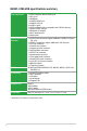
E45M1-I DELUXE specifications summary CPU Chipset Memory Expansion slots Graphics Storage AMD® Dual-Core processor E-450 with AMD RadeonTM HD 6320 Discrete-Class Graphics Support AMD® Turbo Core Technology AMD® FCH A50M (Hudson M1) 2 x DDR3 1333/1066 MHz, max. 8GB, non-ECC, un-buffered memory Single-channel memory architecture * Refer to www.asus.com for the latest Memory QVL (Qualified Vendors List).
E45M1-I DELUXE specifications summary Rear panel ports 1 x PS/2 Keyboard / Mouse combo port 1 x DVI-I port 1 x HDMI port 1 x eSATA 6.0Gb/s port 1 x LAN (RJ-45) port 4 x USB 2.0 ports 2 x USB 3.0/2.0 port (blue, compatible with USB 2.0 devices) 1 x Optical S/PDIF out port 1 x Bluetooth 3.0 adapter 2 x Wi-Fi antenna ports 3 x Audio jacks Internal connectors/ 1 x USB 3.0/2.0 connectors support additional 2 USB 3.0/2.0 ports switches (20-1 pin) 2 x USB 2.0 connectors support additional 4 USB 2.
Chapter 1 Product introduction Thank you for buying an ASUS® E45M1-I DELUXE motherboard! Before you start installing the motherboard, and hardware devices on it, check the items in your motherboard package. Refer to page x for the list of accessories. If any of the items is damaged or missing, contact your retailer. 1.1 Before you proceed Take note of the following precautions before you install motherboard components or change any motherboard settings.
1.2 Motherboard overview 1.2.1 Motherboard layout Ensure that you install the motherboard into the chassis in the correct orientation. The edge with external ports goes to the rear part of the chassis. 1 2 3 4 5 6 7 8 ANTENNA _PORT 17cm(6.7in) TURBO_KEY_II USB3_34 CLRTC O2LED2 ICS 9LRPS483 DVI ESATA6G _USB12 _BT NEC USB3.
1.3 Central Processing Unit (CPU) E35M1-I DELUXE The motherboard comes with an onboard AMD® Dual-Core Processor E-450 with AMD RadeonTM HD 6320 Discrete-Class Graphics and a specially designed CPU heatsink. AMD® Dual-Core Processor E-450 E45M1-I DELUXE AMD® E-450 processor 1.4 System memory 1.4.1 Overview E35M1-I DELUXE DIMM1 DIMM2 The motherboard comes with two Double Data Rate 3 (DDR3) Dual Inline Memory Modules (DIMM) sockets.
1.4.2 Memory configurations You may install 512MB, 1GB, 2GB, and 4GB unbuffered non‑ECC DDR3 DIMMs into the DIMM sockets. • We recommend that you install the memory modules from the blue slots for better overclocking capability. • Due to the memory address limitation on 32-bit Windows® OS, when you install 4GB or more memory on the motherboard, the actual usable memory for the OS can be about 3GB or less.
DDR3-1333 MHz capability Vendors Part No. Size SS/ Chip Brand DS A-Data AD31333001GOU 1GB SS A-Data A-Data A-Data AD63I1B0823EV AD31333G001GOU 2GB 3GB(3 x 1GB) SS SS A-Data - A-Data AXDU1333GC2G9-2G(XMP) 4GB(2 x 2GB) SS - A-Data A-Data Apacer Apacer Apacer CORSAIR CORSAIR CORSAIR CORSAIR CORSAIR Crucial Crucial Crucial ELPIDA ELPIDA G.SKILL G.SKILL G.SKILL G.SKILL G.SKILL G.
DDR3-1333 MHz capability Vendors 8-8-8-20 9 8 9 9-9-9-24 - 1.60V 1.
1.5 Expansion slots In the future, you may need to install expansion cards. The following sub‑sections describe the slots and the expansion cards that they support. Unplug the power cord before adding or removing expansion cards. Failure to do so may cause you physical injury and damage motherboard components. 1.5.1 Installing an expansion card To install an expansion card: 1.
1.6 Jumpers Clear RTC RAM (3-pin CLRTC) E35M1-I DELUXE This jumper allows you to clear the Real Time Clock (RTC) RAM in CMOS. You can clear the CMOS memory of date, time, and system setup parameters by erasing the CMOS RTC RAM data. The onboard button cell battery powers the RAM data in CMOS, which include system setup information such as system passwords. 1 2 CLRTC Normal (Default) 2 3 Clear RTC E45M1-I DELUXE Clear RTC RAM To erase the RTC RAM: 1. Turn OFF the computer and unplug the power cord.
1.7 Connectors 1.7.1 Rear panel connectors 1 2 3 14 13 4 12 5 11 6 10 7 8 9 1. WLAN antenna ports. These ports connect to the WLAN antennas. 2. PS/2 Keyboard / Mouse Combo port. This port is for a PS/2 keyboard or PS/2 mouse. 3. Optical S/PDIF output port. This port connects to an external audio output device via an optical S/PDIF cable. 4. Onboard Bluetooth module.
6. LAN (RJ-45) port. This port allows Gigabit connection to a Local Area Network (LAN) through a network hub. Refer to the table below for the LAN port LED indications. LAN port LED indications ACT/LINK LED Activity Link Speed LED LED SPEED LED Status Description Status Description OFF No link OFF 10 Mbps connection ORANGE Linked ORANGE 100 Mbps connection BLINKING Data activity GREEN 1 Gbps connection LAN port 7. Line In port (light blue).
11. eSATA port. This port connects to an external Serial ATA hard disk drive. 12. DVI-I port. This port is for any DVI-I compatible device and are HDCP compliant, allowing playback of HD DVD, Blu-Ray and other protected content. 13. HDMI port. This port is for a High-Definition Multimedia Interface (HDMI) connector, and is HDCP compliant allowing playback of HD DVD, Blu-ray, and other protected content. 14. USB 2.0 ports 3 and 4.
2. CPU and chassis fan connectors (3-pin CPU_FAN, 3-pin CHA_FAN) Connect the fan cables to the fan connectors on the motherboard, ensuring that the black wire of each cable matches the ground pin of the connector. E35M1-I DELUXE CHA_FAN Rotation +12V GND CPU_FAN Rotation +12V GND E45M1-I DELUXE Fan connectors Do not forget to connect the fan cables to the fan connectors. Insufficient air flow inside the system may damage the motherboard components.
4. Serial ATA 6.0Gb/s connectors (7-pin SATA6G_1~5) E35M1-I DELUXE SATA6G_3 GND RSATA_RXN5 RSATA_RXP5 GND RSATA_TXN5 RSATA_TXP5 GND SATA6G_4 GND RSATA_RXN3 RSATA_RXP3 GND RSATA_TXN3 RSATA_TXP3 GND SATA6G_1 GND RSATA_RXN4 RSATA_RXP4 GND RSATA_TXN4 RSATA_TXP4 GND SATA6G_2 GND RSATA_RXN1 RSATA_RXP1 GND RSATA_TXN1 RSATA_TXP1 GND GND RSATA_RXN2 RSATA_RXP2 GND RSATA_TXN2 RSATA_TXP2 GND These connectors connect to Serial ATA 6.0 Gb/s hard disk drives via Serial ATA 6.0 Gb/s signal cables.
6. System panel connector (10-1 pin F_PANEL) This connector supports several chassis-mounted functions. Reset Ground IDE_LEDIDE_LED+ PIN 1 RESET GND PWR PLEDPLED+ +HDLED PWRBTN PLED E35M1-I DELUXE F_PANEL E45M1-I DELUXE System panel connector • System power LED (2-pin PLED) • This 2-pin connector is for the system power LED. Connect the chassis power LED cable to this connector. The system power LED lights up when you turn on the system power, and blinks when the system is in sleep mode.
8. USB 3.0 connector (20-1 pin USB3_34) E35M1-I DELUXE This connector is for the additional USB 3.0 ports. Connect the bundled USB 3.0 bracket cable to this connector, then install the USB 3.0 bracket to the rear side of the chassis. If your chassis support customised front panel installation, with ASUS USB 3.0 header, you can have a front panel USB 3.0 solution. E45M1-I DELUXE USB3.0 front panel connector 9. USB 2.
1.8 Onboard switches Onboard switches allow you to fine-tune performance when working on a bare or open-case system. This is ideal for overclockers and gamers who continually change settings to enhance system performance. 1. Turbo Key II switch This switch allows you to auto-tune your CPU to enhance the system performance. E35M1-I DELUXE To ensure system performance, turn the switch setting to Enable when the system is powered off.
2. MemOK! switch E35M1-I DELUXE Installing DIMMs that are incompatible with the motherboard may cause system boot failure, and the DRAM_LED near the MemOK! switch lights continuously. Press and hold the MemOK! switch until the DRAM_LED starts blinking to begin automatic memory compatibility tuning for successful boot. E45M1-I DELUXE MemOK! switch • Refer to section 1.9 Onboard LEDs for the exact location of the DRAM_LED. • The DRAM_LED also lights when the DIMM is not properly installed.
1.9 1. Onboard LEDs Standby Power LED E35M1-I DELUXE The motherboard comes with a standby power LED that lights up to indicate that the system is ON, in sleep mode, or in soft-off mode. This is a reminder that you should shut down the system and unplug the power cable before removing or plugging in any motherboard component. The illustration below shows the location of the onboard LED. SB_PWR ON Standby Power OFF Powered Off E45M1-I DELUXE Onboard LED 2.
1.10 Software support 1.10.1 Installing an operating system This motherboard supports Windows® XP / Vista / 7 Operating Systems (OS). Always install the latest OS version and corresponding updates to maximize the features of your hardware. • Motherboard settings and hardware options vary. Refer to your OS documentation for detailed information.
1-20 ASUS E45M1-I DELUXE
Chapter 2 BIOS information 2.1 Managing and updating your BIOS Save a copy of the original motherboard BIOS file to a USB flash disk in case you need to restore the BIOS in the future. Copy the original motherboard BIOS using the ASUS Update utility. 2.1.1 ASUS Update utility The ASUS Update is a utility that allows you to manage, save, and update the motherboard BIOS in Windows® environment. • ASUS Update requires an Internet connection either through a network or an Internet Service Provider (ISP).
The ASUS Update utility is capable of updating itself through the Internet. Always update the utility to avail all its features. Updating from a BIOS file 3. a. Select Update BIOS from file, then click Next. b. Locate the BIOS file from the Open window, then click Open. Follow the onscreen instructions to complete the updating process. 2.1.2 ASUS EZ Flash 2 The ASUS EZ Flash 2 feature allows you to update the BIOS without using an OS‑based utility.
3. Press to switch to the Drive field. 4. Press the Up/Down arrow keys to find the USB flash disk that contains the latest BIOS, and then press . 5. Press to switch to the Folder Info field. 6. Press the Up/Down arrow keys to find the BIOS file, and then press to perform the BIOS update process. Reboot the system when the update process is done. • This function supports USB flash disks with FAT 32/16 format and single partition only.
2.1.4 ASUS BIOS Updater The ASUS BIOS Updater allows you to update BIOS in DOS environment. This utility also allows you to copy the current BIOS file that you can use as a backup when the BIOS fails or gets corrupted during the updating process. The succeeding utility screens are for reference only. The actual utility screen displays may not be same as shown. Before updating BIOS 1. Prepare the motherboard support DVD and a USB flash drive in FAT32/16 format and single partition. 2.
Backing up the current BIOS To backup the current BIOS file using the BIOS Updater Ensure that the USB flash drive is not write-protected and has at least 4MB free space to save the file. 1. At the FreeDOS prompt, type bupdater /o[filename] and press . D:\>bupdater /oOLDBIOS1.rom Filename Extension The [filename] is any user-assigned filename with no more than eight alphanumeric characters for the filename and three alphanumeric characters for the extension. 2.
Updating the BIOS file To update the BIOS file using BIOS Updater 1. At the FreeDOS prompt, type bupdater /pc /g and press . D:\>bupdater /pc /g 2. The BIOS Updater screen appears as below. ASUSTek BIOS Updater for DOS V1.18 Current ROM BOARD: E45M1-I DELUXE VER: 1302 DATE: 06/28/2011 Update ROM BOARD: Unknown VER: Unknown DATE: Unknown PATH: A:\ E45M1ID.ROM A: Note [Enter] Select or Load [Up/Down/Home/End] Move 3.
2.2 BIOS setup program Use the BIOS Setup program to update the BIOS or configure its parameters. The BIOS screens include navigation keys and brief online help to guide you in using the BIOS Setup program. Entering BIOS Setup at startup To enter BIOS Setup at startup: • Press during the Power-On Self Test (POST). If you do not press , POST continues with its routines. Entering BIOS Setup after POST To enter BIOS Setup after POST: • Press ++ simultaneously.
BIOS menu screen The BIOS setup program can be used under two modes: EZ Mode and Advanced Mode. You can change modes from the Exit menu or from the Exit/Advanced Mode button in the EZ Mode/Advanced Mode screen. EZ Mode By default, the EZ Mode screen appears when you enter the BIOS setup program. The EZ Mode provides you an overview of the basic system information, and allows you to select the display language, system performance mode and boot device priority.
Advanced Mode The Advanced Mode provides advanced options for experienced end-users to configure the BIOS settings. The figure below shows an example of the Advanced Mode. Refer to the following sections for the detailed configurations. To access the EZ Mode, click Exit, then select ASUS EZ Mode.
Pop-up window Select a menu item and press to display a pop-up window with the configuration options for that item. Scroll bar A scroll bar appears on the right side of a menu screen when there are items that do not fit on the screen. Press the Up/Down arrow keys or / keys to display the other items on the screen. Navigation keys At the bottom right corner of the menu screen are the navigation keys for the BIOS setup program.
2.3.1 System Language [English] 2.3.2 System Date [Day xx/xx/xxxx] 2.3.3 System Time [xx:xx:xx] 2.3.4 Security Allows you to choose the BIOS language version from the options. Configuration options: [English] Allows you to set the system date. Allows you to set the system time. The Security menu items allow you to change the system security settings. • If you have forgotten your BIOS password, erase the CMOS Real Time Clock (RTC) RAM to clear the BIOS password. See section 1.
To set a user password: 1. Select the User Password item and press . 2. From the Create New Password box, key in a password, then press . 3. Confirm the password when prompted. To change a user password: 1. Select the User Password item and press . 2. From the Enter Current Password box, key in the current password, then press . 3. From the Create New Password box, key in a new password, then press . 4. Confirm the password when prompted.
2.4.1 Ai Overclock Tuner [Auto] Allows you to select the CPU overclocking options to achieve the desired CPU internal frequency. Select any of these preset overclocking configuration options: [Auto] Loads the optimal settings for the system. [Manual] Allows you to individually set overclocking parameters. APU Frequency [XXX] This item appears only when you set the Ai Overclock Tuner item to [Manual]. Use the <+> and <-> keys to adjust the value.
2.4.6 [+] [–] VDDNB Offset Mode Sign [+] To offset the voltage by a positive value. To offset the voltage by a negative value. VDDNB Voltage [Auto] Allows you to set the VDDNB Offset voltage. The values range from -0.3V to +0.5V with a 0.00625V interval. 2.4.7 DRAM Voltage [Auto] Allows you to set the DRAM voltage. The values range from 1.35V to 2.30V with a 0.01V interval. According to Intel CPU specification, DIMMs with voltage requirement over 1.65V may damage the CPU permanently.
2.5 Advanced menu The Advanced menu items allow you to change the settings for the CPU and other system devices. Be cautious when changing the settings of the Advanced menu items. Incorrect field values can cause the system to malfunction. EFI BIOS Utility - Advanced Mode Ai Tweaker Main Advanced > CPU Configuration Exit Monitor Boot Tool CPU Configuration Parameters > SATA Configuration > USB Configuration > NB Configuration > Onboard Devices Configuration > APM 2.5.
2.5.2 SATA Configuration While entering Setup, the BIOS automatically detects the presence of SATA devices. The SATA Port items show Not Present if no SATA device is installed to the corresponding SATA port. OnChip SATA Channel [Enabled] Enables or disables onboard channel SATA port. Configuration options: [Disabled] [Enabled] OnChip SATA Type [IDE] Allows you to set the SATA configuration. [IDE] Set to [IDE] when you want to use the Serial ATA hard disk drives as Parallel ATA physical storage devices.
2.5.4 NB Configuration IGFX Multi-Monitor [Disabled] Enables or disables the Internal Graphics Device Multi-Monitor support for add-on VGA devices. And the memory size of Internal Graphics Device will keep memory reserved. Configuration options: [Disabled] [Enabled] Primary Video Device [PCIE Video] Selects the primary display device. Configuration options: [IGFX Video] [PCIE Video] Integrated Graphics [Auto] Enables the integrated graphics controller. Configuration options: [Auto] [Force] 2.5.
2.5.6 APM Restore AC Power Loss [Power Off] [Power On] [Power Off] [Last State] The system goes into on state after an AC power loss. The system goes into off state after an AC power loss. The system goes into either off or on state, whatever the system state was before the AC power loss. Power On By PS/2 Keyboard [Disabled] [Disabled] [Space Bar] [Ctrl-Esc] [Power Key] Disables the Power On by a PS/2 keyboard. Sets the Space Bar on the PS/2 keyboard to turn on the system.
2.6 Monitor menu The Monitor menu displays the system temperature/power status, and allows you to change the fan settings. EFI BIOS Utility - Advanced Mode Main Ai Tweaker Exit Advanced Monitor CPU Temperature +45ºC / +113ºF MB Temperature +34ºC / +93ºF CPU Fan Speed Boot Tool 3325 RPM Chassis Fan Speed N/A CPU Q-Fan Control Enabled CPU Fan Speed Low Limit 600 RPM CPU Fan Profile Standard CPU Voltage +1.404 V 3.3V Voltage +3.312 V 5V Voltage +5.
CPU Fan Profile [Standard] This item appears only when you enable the CPU Q-Fan Control feature and allows you to set the appropriate performance level of the CPU fan. [Standard] Sets to [Standard] to make the CPU fan automatically adjust depending on the CPU temperature. [Silent] Sets to [Silent] to minimize the fan speed for quiet CPU fan operation. [Turbo] Sets to [Turbo] to achieve maximum CPU fan speed. [Manual] Sets to [Manual] to assign detailed fan speed control parameters.
2.7 Boot menu The Boot menu items allow you to change the system boot options. EFI BIOS Utility - Advanced Mode Ai Tweaker Main Exit Advanced Bootup NumLock State Full Screen Logo Wait For ‘F1’ If Error Option ROM Messages Monitor On Boot Tool Select the keyboard NumLock state Enabled Enabled Force BIOS Setup Mode EZ Mode Boot Option Priorities Boot Override →←: Select Screen ↑↓: Select Item Enter: Select +/-: Change Opt.
2.7.5 Setup Mode [EZ Mode] [EZ Mode] Sets EZ Mode as the default screen for entering the BIOS setup program. 2.7.6 Boot Option Priorities [Advanced Mode] Sets Advanced Mode as the default screen for entering the BIOS setup program. These items specify the boot device priority sequence from the available devices. The number of device items that appears on the screen depends on the number of devices installed in the system.
2.8 Tools menu The Tools menu items allow you to configure options for special functions. Select an item then press to display the submenu. EFI BIOS Utility - Advanced Mode Ai Tweaker Main Advanced Exit Monitor Boot Tool Be used to update BIOS > ASUS EZ Flash Utility > ASUS O.C. Profile 2.8.1 ASUS EZ Flash Utility Allows you to run ASUS EZ Flash 2. Press [Enter] to launch the ASUS EZ Flash 2 screen. For more details, refer to section 2.1.2 ASUS EZ Flash 2. 2.8.2 ASUS O.C.
2.9 Exit menu The Exit menu items allow you to load the optimal default values for the BIOS items, and save or discard your changes to the BIOS items. You can access the EZ Mode from the Exit menu. Exit Load Optimized Defaults Save Changes & Reset Discard Changes & Exit ASUS EZ Mode Launch EFI Shell from filesystem device Load Optimized Defaults This option allows you to load the default values for each of the parameters on the Setup menus.
ASUS contact information ASUSTeK COMPUTER INC. Address Telephone Fax E-mail Web site Technical Support Telephone Online support 15 Li-Te Road, Peitou, Taipei, Taiwan 11259 +886-2-2894-3447 +886-2-2890-7798 info@asus.com.tw www.asus.com.tw +86-21-38429911 support.asus.
(510)739-3777/(510)608-4555 800 Corporate Way, Fremont, CA 94539. Asus Computer International Date : Signature : Representative Person’s Name : Jul. 20. 2011 Steve Chang / President This device complies with part 15 of the FCC Rules. Operation is subject to the following two conditions: (1) This device may not cause harmful interference, and (2) this device must accept any interference received, including interference that may cause undesired operation.