
User Manual
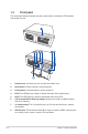

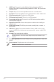
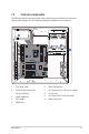
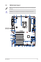
Table Of Contents
- Notices
- Safety information
- Chapter 1
- Chapter 3
- BIOS setup
- 3.1 BIOS setup program
- 3.2 Main menu
- 3.3 Advanced menu
- 3.3.1 PCH-FW Configuration
- 3.3.2 Trusted Computing
- 3.3.3 CPU Configuration
- 3.3.4 Graphics Configuration
- 3.3.5 PCI Express Configuration
- 3.3.6 CSM Configuration
- 3.3.7 Super IO Configuration
- 3.3.8 Serial Console Configuration
- 3.3.9 SATA Configuration
- 3.3.10 USB Configuration
- 3.3.11 Onboard Devices Configuration
- 3.3.12 APM Configuration
- 3.3.13 EzFlash
- 3.3.14 Watchdog Timer
- 3.3.15 Network Stack Configuration
- 3.3.16 Miscellaneous
- 3.4 Hardware Monitor menu
- 3.5 Security menu
- 3.6 Boot menu
- 3.7 Exit menu
- Appendix
- BIOS setup

1-7
ASUS EBE-4U
PCI_4
PCI_5
PCI_2
PCI_1
PCI_3
SPEAKER
CHASSIS
AT_ATX_SEL
WDT_EN
CLRTC
F_PANEL
LPC_DEBUG
USB78
USB56
I2C
LPT
AAFP
TPM
EATXPWR
COM6
COM5COM8COM7
CPU_FAN
CHA_FAN
BATTERY
PCIEX16_1
PCIEX16_2
Super
I/O
ASM
1085
ALC
887
LGA1151
Intel
®
H110
Intel
®
I219V
Intel
®
I211AT
DDR4 DIMM_A1* (64bit, 288-pin module)
2280 2260 2242
M.2(SOCKET3)
M.2(SOCKET3)
PCIE SATA IRST
X V X
DDR4 DIMM_B1* (64bit, 288-pin module)
AUDIO
KBMS
COM1
COM2
LAN2_U32G1_34
LAN1_U32G1_12
SATA6G_1 SATA6G_2
SATA6G_3
ATX12V
COM2_SEL
COM1_SEL
USB9 USB10
COM3 COM4
GPIO_CON
HDMI
VGA
BUZZER
1.5 Internal components
The illustration below is the internal view of the system when you remove the chassis cover
and the power supply unit. The installed components are labeled for your reference.
1. Front panel cover
2. 5.25-inch optical drive bays
3.5-inch drive bay
3. Power supply unit
4. CPU socket
5. DIMM slots
6. ASUS motherboard
7. PCI Express 3.0/2.0 x16 slot (x16 mode)
8. 5 x PCI slots
9. PCI Express 2.0 x16 slot (x4 mode)
10. Metal bracket lock