
User Manual
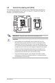
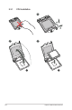

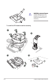
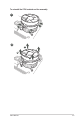
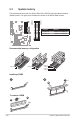
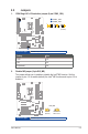

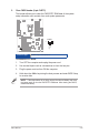
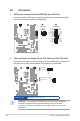
Table Of Contents
- Notices
- Safety information
- Chapter 1
- Chapter 3
- BIOS setup
- 3.1 BIOS Setup program
- 3.2 Main menu
- 3.3 Advanced menu
- 3.3.1 PCH-FW Configuration
- 3.3.2 Trusted Computing
- 3.3.3 CPU Configuration
- 3.3.4 Graphics Configuration
- 3.3.5 PCI Express Configuration
- 3.3.6 AMT Configuration
- 3.3.7 CSM Configuration
- 3.3.8 Super IO Configuration
- 3.3.9 Serial Console Redirection
- 3.3.10 SATA And RST Configuration
- 3.3.11 Network Stack Configuration
- 3.3.12 USB Configuration
- 3.3.13 NVMe Configuration
- 3.3.14 Onboard Devices Configuration
- 3.3.15 EZ-Flash
- 3.3.16 APM Configuration
- 3.3.17 Watchdog Timer
- 3.3.19 Miscellaneous
- 3.4 Hardware Monitor menu
- 3.5 Security menu
- 3.6 Boot menu
- 3.7 Exit menu
- Appendix
- BIOS setup

Chapter 2: Motherboard information
2-14
2.6 Connectors
1. EATX power connectors (24-pin EATXPWR, 8-pin EATX12V)
Correctly orient the ATX power supply plugs into these connectors and push
down rmly until the connectors completely t.
A
B
EATX12V
PIN 1
GND
+5 Volts
+5 Volts
+5 Volts
-5 Volts
GND
GND
GND
PSON#
GND
-12 Volts
+3 Volts
+3 Volts
+12 Volts
+12 Volts
+5V Standby
Power OK
GND
+5 Volts
GND
+5 Volts
GND
+3 Volts
+3 Volts
B
A
EATXPWR
PIN 1
GND
GND
GND
GND
+12V
+12V
+12V
+12V
CAUTION! Do not forget to connect the fan cables to the fan connectors.
Insufcient air flow inside the system may damage the motherboard
components. These are not jumpers! Do not place jumper caps on the fan
connectors!
2. CPU and Chassis Fan headers (4-pin CPU_FAN, 4-pin CHA_FAN 1/2/3)
Connect the fan cables to the fan headers on the motherboard, ensuring that
the black wire of each cable matches the ground pin of the header.
A
C
A
B
C
D
CPU_FAN
CHA_FAN2
FAN_PWM
FAN_IN
12V
GND
CHA_FAN3
CHA_FAN1
FAN_PWM
FAN_IN
12V
GND
B
D
Connector type
WAFER HD 4p, 2.54mm pitch, S/T