EBE-4U / EBE-4UG ASUS IPC (Industrial Computer Barebone) User’s Manual EBE-4U EBE-4UG Applicable for products with P/N of 90AE0067* & 90AE0068* & 90AE00H7* & 90AE00H8*
E22594 Revised Edition v2 September 2023 Copyright © 2023 ASUSTeK Computer Inc. All Rights Reserved. No part of this manual, including the products and software described in it, may be reproduced, transmitted, transcribed, stored in a retrieval system, or translated into any language in any form or by any means, except documentation kept by the purchaser for backup purposes, without the express written permission of ASUSTeK Computer Inc. (“ASUS”).
Table of contents Notices.............................................................................................................v Safety information...........................................................................................vi About this guide............................................................................................. vii System package contents............................................................................. viii Chapter 1 System introduction 1.
Table of contents 3.3.7 Super IO Configuration......................................................... 3-8 3.3.8 Serial Console Redirection................................................... 3-9 3.3.9 SATA Configuration............................................................ 3-10 3.3.10 Network Stack Configuration.............................................. 3-11 3.3.11 USB Configuration.............................................................. 3-11 3.3.12 NVMe Configuration.................
Notices ASUS Recycling/Takeback Services ASUS recycling and takeback programs come from our commitment to the highest standards for protecting our environment. We believe in providing solutions for you to be able to responsibly recycle our products, batteries, other components, as well as the packaging materials. Please go to http://csr.asus.com/english/Takeback.htm for the detailed recycling information in different regions.
Safety information Electrical safety • To prevent electric shock hazard, disconnect the power cable from the electric outlet before relocating the system. • When adding or removing devices to or from the system, ensure that the power cables for the devices are unplugged before the signal cables are connected. If possible, disconnect all power cables from the existing system before you add a device.
About this guide Audience This guide provides general information and installation instructions about ASUS EBE4U barebone system. This guide is intended for users and administrators with experience handling hardware and PC components. How this guide is organized This guide contains the following parts: 1. Chapter 1: System introduction 2. This chapter gives a general description of ASUS EBE-4U.
System package contents Check your EBE-4U system package for the following items. If any of the items is damaged or missing, contact your retailer immediately. Item Description 1. ASUS EBE-4U barebone system with • ASUS industrial motherboard • Industrial power supply unit • Standard 19” Rackmount 4U chassis with 1.2mm durable SGCC sheet metal • 1 x M.2 screw • 1 accessory box (labeled with P/N: 13AE0060Mxxxxx), including a key, screws and clamp hooks 2. Cables • Power SW cable • SATA 6G cable 3.
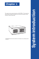
This chapter gives a general description of ASUS EBE-4U. The chapter lists system features, physical descriptions of the front and rear panels, and an overview of internal components. The illustrations in this user manual are for reference only. Actual product may vary.
1.1 Welcome! Thank you for choosing the ASUS EBE-4U! The ASUS EBE-4U provides cutting-edge performance and uncompromised reliability for industrial use. The system is powered by the ASUS motherboard that supports Intel® Core™ i9/i7/i5/i3, Pentium® and Celeron® processors in the Intel® LGA1700 socket. The system supports up to 32 GB of system memory using DDR4 3200/2933/2666/2400 MHz DIMMs. High-resolution graphics via integrated graphics controller or PCI Express x16 slots, SATA 6.0Gb/s, USB 3.
Main components DP CPU_FAN EATX12V VGA DIGI+ VRM COM2_SEL LGA1700 ATX_PWR COM1_SEL USB_5~8 LAN2_U32G2_12 DDR4 DIMM_B (64bit, 288-pin module) DDR4 DIMM_A (64bit, 288-pin module) COM1 COM2 HDMI USB_914 CHA_FAN2 LAN1_U32G1_34 BATTERY AUDIO PCIEX16(G5) Intel® I219V PCI_1 Intel® I210AT Intel® H610 PCI_2 TPM 128Mb BIOS PCIEX16(G3) Super I/O BUZZER ASM 1083 PCI_4 ALC 897 2280 SMBDATA_SW SMBCLK_SW COM3 COM4 PCIE SATA 3.
1.3 Front panel The front panel includes the optical drive bays, power button, reset button, LED indicators and several I/O ports. 1-4 1. Cabinet cover. Use the key to lock or unlock the cabinet cover. 2. Reset button. Press this button to reset the system. 3. Power button. Press this button to turn the system on. 4. PLED. The LED lights up or blinks to indicate the status of the system power. 5. HLED. The LED lights up or blinks to indicate the status of the HDD. 6. 5.
1.4 Rear panel The system rear panel includes the power connector and several I/O ports that allow convenient connection of devices. 1. VGA port. This port is for VGA-compatible devices such as a VGA monitor. 2. DisplayPort. This port is for a DisplayPort-compatible device. 3. HDMI™ port. This port is for a High-Definition Multimedia Interface (HDMI™) connector, and is HDCP compliant allowing playback of HD DVD, Blu-ray, and other protected content. 4. Serial ports.
10. LAN (RJ-45) ports. These ports allow Gigabit connection to a Local Area Network (LAN) through a network hub. LAN port LED indications Activity/Link LED Speed LED Status Description Status Description OFF No link OFF 10Mbps connection ORANGE Linked ORANGE 100Mbps connection BLINKING Data activity GREEN 1Gbps connection ACT/LINK LED SPEED LED LAN port 11. Power supply unit fan vent. This vent is for the PSU fan that provides ventilation inside the power supply unit. 12.
1.5 Internal components The illustration below is the internal view of the system when you remove the chassis cover and the power supply unit. The installed components are labeled for your reference. LGA1700 1. Front panel cover 6. ASUS motherboard 2. 5.25-inch optical drive bays 7. PCI Express 5.0 x16 slot 3.5-inch drive bay 8. 4 x PCI slots 3. Power supply unit 9. PCI Express 3.0/2.0 x16 slot (x4 mode) 4. CPU socket 10. PCI Express 3.0/2.0 x1 slot 5. DIMM slots 11.
1-8 Chapter 1: System introduction
This chapter provides details about the motherboard that comes with the system. This chapter includes the motherboard layout, jumper settings, and connector locations.
2.1 Before you proceed Take note of the following precautions before you install motherboard components or change any motherboard settings. CAUTION! 2-2 • Unplug the power cord from the wall socket before touching any component. • Before handling components, use a grounded wrist strap or touch a safely grounded object or a metal object, such as the power supply case, to avoid damaging them due to static electricity. • Hold components by the edges to avoid touching the ICs on them.
2.2 Motherboard layout NOTE: Place nine screws into the holes indicated by circles to secure the motherboard to the chassis. Do not overtighten the screws! Doing so can damage the motherboard. CAUTION! 2 1 3 4 5 24.4cm(9.6in) DP CPU_FAN EATX12V VGA DIGI+ VRM COM2_SEL USB_5~8 LGA1700 LAN2_U32G2_12 Place this side towards the rear of the chassis ATX_PWR COM1_SEL DDR4 DIMM_B (64bit, 288-pin module) DDR4 DIMM_A (64bit, 288-pin module) COM1 COM2 HDMI 1 2 USB_914 BATTERY 1 6 30.
2-4 Connectors/Jumpers/Slots Page 1. COM RING/+5V/+12V selection (COM1/2_SEL) 2-13 2. ATX Power connectors (24-pin ATXPWR, 2 x 4-pin EATX12V) 2-17 3. CPU and Chassis Fan headers (4-pin CPU_FAN, 4-pin CHA_FAN) 2-17 4. Intel® LGA1700 CPU socket 2-5 5. DDR4 U-DIMM slots 2-10 6. USB 2.0 header (10-1pin USB914,) 2-18 7. TPM header (14-1 pin TPM) 2-18 8. I2C header (6-1 pin I2C) 2-19 9. M.2 slot (SOCKET 3) 2-19 10. System Panel header (10-1 pin F_PANEL) 2-20 11.
2.3 Central Processing Unit (CPU) The motherboard comes with a surface mount LGA1700 socket designed for the Intel® Core™ i9 / Core™ i7 / Core™ i5 / Core™ i3, Pentium®, and Celeron® Processors. LGA1700 IMPORTANT: Unplug all power cables before installing the CPU. CAUTION! • Ensure that you install the correct CPU designed for LGA1700 socket only.
2.3.1 Installing the CPU • Ensure that you install the correct CPU designed for LGA1700 socket only. DO NOT install a CPU designed for LGA1155, LGA1156, LGA1151, and LGA1200 sockets on the LGA1700 socket. • ASUS will not cover damages resulting from incorrect CPU installation/removal, incorrect CPU orientation/placement, or other damages resulting from negligence by the user. 1 A B 2-6 Take caution when lifting the load lever, ensure to hold onto the load lever when releasing the load lever.
2 3 A B 4 5 B A Chapter 2: Motherboard information 2-7
2.3.2 CPU heatsink and fan assembly installation CAUTION! Apply the Thermal Interface Material to the CPU heatsink and CPU before you install the heatsink and fan if necessary.
4 Bottom side of motherboard • We recommend using a LGA1700 compatible cooling system on an Intel® 600 series motherboard. • Additional holes for LGA1200 compatible cooling systems are also available on ASUS’ Intel® 600 series motherboards, however, we still strongly advise consulting with your cooling system vendor or manufacturer on the compatibility and functionality of the cooling system. • Push-pin type LGA1200 compatible cooling systems cannot be installed to this motherboard.
2.4 System memory This motherboard comes with two Double Data Rate 4 (DDR4) Dual Inline Memory Module (DIMM) sockets.
2 A A B 3 A To remove a DIMM B Chapter 2: Motherboard information 2-11
2.5 1. Jumpers Clear RTC RAM (2-pin CLRTC) This header allows you to clear the CMOS RTC RAM data of the system setup information such as date, time, and system passwords. CLRTC +3V_BAT_RTC GND PIN 1 Connector type HEADER 1x2p, 2.54mm pitch, S/T To erase the RTC RAM: 1. Turn OFF the computer and unplug the power cord. 2. Use a metal object such as a screwdriver to short the two pins. 3. Plug the power cord and turn ON the computer. 4.
2. COM Ring/+5V/+12V selection jumper (6-pin COM1/2_SEL) A A B B COM1_SEL COM2_SEL 2 4 3 1 +12V 3. Setting Pins +12V 1-2 +5V 3-4 Ring (Default) 5-6 6 5 +5V RI (Default) AT/ATX mode selection (3-pin AT_ATX_SEL) AT_ATX_SEL 1 2 ATX mode (Default) 2 3 AT mode Pins 1-2 (Default) ATX mode 2-3 AT mode Connector type HEADER 1x3p, 2.
4. 3-pin SMBDATA_SW SMBDATA_SW 1 2 2 3 Eanble PCIe SMBus connection (Default) 5.
2.6 Connectors 2.6.1 Rear panel connectors 1 6 2 7 3 2 4 8 5 9 10 1. Video Graphics Adapter (VGA) port. This 15-pin port is for a VGA monitor or other VGA-compatible devices. 2. COM ports (COM, RS232/RS422/RS485). These ports connect modems, or other devices that conform with serial specification. 3. USB 2.0 ports. These 4-pin Universal Serial Bus (USB) ports are for USB 2.0 devices. 4. LAN (RJ-45) ports.
9. USB 3.2 Gen 1 (up to 5Gbps) ports. These 9-pin Universal Serial Bus (USB) ports are for USB 3.2 Gen 1 devices. 10. Microphone port (pink). This port connects to a microphone. Refer to the audio configuration table for the function of the audio ports in 2, 4, 5.1, or 7.1-channel configuration. Audio 2, 4, 5.1 or 7.1-channel configuration Headset 2-channel 4-channel 5.1-channel 7.
2.6.2 1. Internal connectors ATX Power connectors (24-pin ATXPWR, 2 x 4-pin EATX12V) Correctly orient the ATX power supply plugs into these connectors and push down firmly until the connectors completely fit. A A B ATX_PWR GND GND GND GND EATX12V +12V +12V +12V +12V PIN 1 B GND +5 Volts +5 Volts +5 Volts -5 Volts GND GND GND PSON# GND -12 Volts +3 Volts +3 Volts +12 Volts +12 Volts +5V Standby Power OK GND +5 Volts GND +5 Volts GND +3 Volts +3 Volts PIN 1 Connector type 2.
3. USB 2.0 header (10-pin USB914) This header is for USB 2.0 ports. Connect a USB cable to the header. The USB header complies with USB 2.0 specification that supports up to 480 Mbps connection speed. USB914 NC GND USB_P9+ USB_P9USB+5V GND USB_P14+ USB_P14USB+5V PIN 1 Connector type HEADER 2x5p, K9, 2.54mm pitch CAUTION! Never connect a 1394 cable to the USB connector. Doing so will damage the motherboard. NOTE: 4. The USB cable is purchased separately.
5. I2C header PWR 3.3V NC The I2C (Inter-Integrated Circuit) header allows you to connect an I2C compatible IoT security module. I2C I2C_CLK I2C_DATA GND PIN 1 Connector type 6. HEADER 2x3p, K6, 2.0mm pitch M.2 slot (SOCKET 3) This slot allows you to install an M.2 SSD module. M.2(SOCKET3) Connector type NGFF KEY-M 67P, 8.5H NOTES: • The M.2 SSD module is purchased separately. • This slot supports M Key and 2242/2260/2280 storage devices.
7. System Panel header (10-1 pin F_PANEL) This header supports several chassis-mounted functions. PWR_BTN F_PANEL PIN 1 HDD_LED+ HDD_LEDGND O_RSTCON#_PR NC PLED+ PLEDPWRBTN#_PANEL GND +PWR_LED +HDD_LED Connector type RESET HEADER 2x5p, K10, 2.54mm pitch • System power LED (2-pin +PWR_LED) • This 2-pin header is for the system power LED. Connect the chassis power LED cable to this header.
8. Speaker header (4-pin SPEAKER) The 4-pin header is for the chassis-mounted system warning speaker. The speaker allows you to hear system beeps and warnings. SPEAKER +5V GND GND Speaker Out PIN 1 Connector type 9. HEADER 1x4p, 2.54mm pitch, S/T Chassis Intrusion header (4-1 pin_CHASSIS) This header is for a chassis-mounted intrusion detection sensor or switch. Connect one end of the chassis intrusion sensor or switch cable to this connector.
10. SATA 6.0Gb/s ports (7-pin SATA6G_1-4) These ports connect to SATA 6.0 Gb/s hard disk drives or an optical drive via SATA 6.0 Gb/s signal cables. A SATA6G_3 SATA6G_4 GND RSATA_TXP RSATA_TXN GND RSATA_RXN RSATA_RXP GND B C A B C D Connector type 11.
12. PS/2 Keyboard & Mouse header (8-pin KBMS_CON) +5V_ZPS2 GND O_MS_DATA_R O_MS_CLK_R This header is for an IBM PS/2-compatible keyboard or mouse. KBMS_CON +5V_ZPS2 GND O_KB_DATA_R O_KB_CLK_R PIN 1 Connector type 13. WAFER HD 2x4p, 2.0mm pitch, S/T LPT header (26-1 pin LPT) LPT_XAFD# LPT_ERROR# LPT_XINIT# LPT_XSLIN# GND GND GND GND GND GND GND GND The LPT (Line Printing Terminal) header supports devices such as a printer.
14. COM Port headers (10-pin COM3 - COM6) B C D A B C Connector type COM3 COM4 COM5 COM6 PIN 1 DCD# TXD GND RTS# Ring A RXD DTR# DSR# CTS# These headers are for serial (COM) ports. Connect the serial port cables to these headers, then install the module to a slot opening at the back of the system chassis. D HEADER 2x5p, K10, 2.54mm pitch NOTE: The serial port cable is purchased separately.
15. Front Panel Audio header (10-1 pin AAFP) A_JD_HPOUT A_GND NC A_JD_FMIC1 This header is for a chassis-mounted front panel audio I/O module that supports HD Audio standard. Connect one end of the front panel audio I/O module cable to this header. AAFP A_FMIC1_L A_FMIC1_R A_HPOUT_R A_JD_FRONT A_HPOUT_L PIN 1 Connector type HEADER 2x5p, K8, 2.
16. COM Debug header (5-1 pin COM_DEBUG) GND GND debug_control This header allows connection to a COM Debug card. COM_DEBUG Connector type +3V TXD PIN 1 HEADER 2x3p, K3, 2.54 mm pitch, S/T NOTE: The COM Debug Card is purchased separately.
Chapter 3 BIOS setup This chapter provides a detailed guide to navigating and setting up the BIOS.
Scan the QR code to view the BIOS update guide. 3.1 BIOS Setup program Use the BIOS Setup program to update the BIOS or configure its parameters. The BIOS screens include navigation keys and brief online help to guide you in using the BIOS Setup program. To enter BIOS Setup at startup: Press or during the Power-On Self Test (POST). If you do not press or , POST continues with its routines. To enter BIOS Setup after POST: • Press ++ simultaneously.
3.1.1 BIOS menu screen Menu bar The menu bar on top of the screen has the following main items: Main For changing the basic system configuration Advanced For changing the advanced system settings Hardware Monitor For displaying the system temperature and changing the fan settings Security For configuring the system security settings Boot For changing the system boot configuration. Exit For selecting the save options and default options.
3.3 Advanced menu The Advanced menu items allow you to change the settings for the CPU and other system devices. Be cautious when changing the settings of the Advanced menu items. Incorrect field values can cause the system to malfunction. 3.3.1 PCH-FW Configuration TPM Device Selection This item allows you to select the TPM device. Configuration options: [dTPM] [PTT] 3.3.2 Trusted Computing Security Device Support This item allows you to enable or disable BIOS support for security devices.
Intel(R) SpeedStep(tm) This item allows your system to support more than two frequency ranges. Configuration options: [Disabled] [Enabled] Intel(R) Speed Shift Technology This item allows you to enable or disable Intel(R) Speed Shift Technology support. When enabled, CPPC v2 interface allows hardware controlled P-state. Configuration options: [Disabled] [Enabled] Turbo Mode This item allows you to enable or disable Turbo Mode for your processor.
3.3.5 PCI Express Configuration Allows you to select a PEG or PCI graphical device. PCIEX16 (G5) Slot PCIEx16 (G5) Slot This item allows you to enable or disable the PCIEX16 (G5) slot. Configuration options: [Disabled] [Enabled] ASPM This item allows you to control the Active State Power Management on both NB (NorthBridge) side and SB (SouthBridge) side of the DMI Link. Configuration options: [Disabled] [L0s] [L1] [L0sL1] L1 Substates This item allows you to select the PCI Express L1 Substates settings.
Detect Timeout Allows you to set the time (milliseconds) of waiting for link to exit Detect state for enabled ports before assuming there is no device and potentially disabling the port. Use the <+> and <-> keys to adjust the value or input the desired value. Hot Plug These items allow you to enable/disable PCIEX16 (G3) slot Hot Plug support. Configuration options: [Disabled] [Enabled] Detect Non-Compliance Device Allows you to enable or disable the detection function of non-compliance PCI Express device.
Storage Controls the execution of UEFI and Legacy Storage OpROM. Configuration options: [Do not launch] [UEFI] [Legacy] Video Controls the execution of UEFI and Legacy Video OpROM. Configuration options: [Do not launch] [UEFI] [Legacy] Other PCI devices Determines OpROM execution policy for devices other than Network, Storage, or Video. Configuration options: [Do not launch] [UEFI] [Legacy] 3.3.
Serial Port 5 Configuration Serial Port Allows you to enable or disable the serial port (COM).Configuration options: [Disabled] [Enabled] Serial Port 6 Configuration Serial Port Allows you to enable or disable the serial port (COM).Configuration options: [Disabled] [Enabled] Parallel Port Configuration Parallel Port Allows you to enable or disable the Parallel port (LPT/LPTE).Configuration options: [Disabled] [Enabled] The following items appear only when you set Parallel Port to [Enabled].
Parity A parity bit can be sent with the data bits to detect some transmission errors. Configuration options: [None] [Even] [Odd] [Mark] [Space] [None] Disables parity check. [Even] Parity bit is 0 if the num of 1’s in the data bits is even. [Odd] Parity bit is 0 if the num of 1’s in the data bits is odd. [Mark] Parity bit is always 1. [Space] Parity bit is always 0. Mark and Space Parity do not allow for error detection. Stop Bits Stop bits indicate the end of a serial data packet.
[AHCI] Set to [AHCI] when you want the SATA hard disk drives to use the AHCI (Advanced Host Controller Interface). The AHCI allows the onboard storage driver to enable advanced Serial ATA features that increases storage performance on random workloads by allowing the drive to internally optimize the order of commands. SATA6G_1/2/3/4 Allow you to enable/disable the SATA6G_1/2/3/4 port. Configuration options: [Disabled] [Enabled] Hot Plug Allow you to enable/disable the hot plug function.
options: [Disabled] [Enabled] U32G2_1/2 Allows you to enable or disable the USB port. Once set to [Disabled], any USB devices plugged into the connector will not be detected by BIOS or OS. Configuration options: [Disabled] [Enabled] U32G1_3/4 Allows you to enable or disable the USB port. Once set to [Disabled], any USB devices plugged into the connector will not be detected by BIOS or OS. Configuration options: [Disabled] [Enabled] USB5-9, 14 Allows you to enable or disable USB port.
3.3.14 Miscellaneous DMI/OPI Configuration DMI LINK ASPM Control This item allows you to control the Active State Power Management on SA side of the DMI Link. Configuration options: [Disabled] [Auto] [ASPM L0s] [ASPM L1] [ASPM L0sL1] PCI Express Configuration DMI Link ASPM Control This item allows you to control the Active State Power Management of the DMI Link. Configuration options: [Disabled] [L1] [Auto] 3.3.
3.3.16 EzFlash Enter Ez-Flash mode This item allows you to run EzFlash utility. When you press , a confirmation message appears. Use the left/right arrow key to select between [Yes] or [No], then press to confirm your choice. 3.3.17 Watchdog Timer Watchdog Support This item allows you to enable or disable Watchdog timer. Configuration options: [Enabled] [Disabled] The following items appear when you set Watchdog Support to [Enabled].
3.5 Security menu This menu allows a new password to be created or a current password to be changed. The menu also enables or disables the Secure Boot state and lets the user configure the System Mode state. Administrator Password If you have set an administrator password, we recommend that you enter the administrator password for accessing the system. To set an administrator password: 1. Select the Administrator Password item and press . 2.
Secure Boot Mode In Custom mode, Secure Boot policy variables can be configured by a physically present user without full authentication. Configuration options: [Standard] [Custom] Key Management The Key Management item allows you to modify Secure Boot variables and set Key Management page. Platform Key (PK) / Key Exchange Keys / Authorized Signatures / Forbidden Signatures Configuration options: [Update] [Append] 3.6 Boot menu The Boot menu items allow you to change the system boot options.
3.7 Exit menu The Exit menu items allow you to save or discard your changes to the BIOS items. Save Changes & Exit This option allows you to save your changes and exit the Setup program. When you select this option or if you press , a confirmation window appears. Select Yes to save changes and exit. Discard Changes & Exit This option allows you to exit the Setup program without saving your changes. When you select this option or if you press , a confirmation window appears.
3-18 Chapter 3: BIOS setup
Appendix Notices FCC Compliance Information Responsible Party: Address: Phone / Fax No: Asus Computer International 48720 Kato Rd., Fremont, CA 94538, USA (510)739-3777 / (510)608-4555 This device complies with part 15 of the FCC Rules. Operation is subject to the following two conditions: (1) This device may not cause harmful interference, and (2) this device must accept any interference received, including interference that may cause undesired operation.
Compliance Statement of Innovation, Science and Economic Development Canada (ISED) This device complies with Innovation, Science and Economic Development Canada licence exempt RSS standard(s). Operation is subject to the following two conditions: (1) this device may not cause interference, and (2) this device must accept any interference, including interference that may cause undesired operation of the device.
ASUS Recycling/Takeback Services ASUS recycling and takeback programs come from our commitment to the highest standards for protecting our environment. We believe in providing solutions for you to be able to responsibly recycle our products, batteries, other components as well as the packaging materials. Please go to http://csr.asus.com/english/Takeback.htm for detailed recycling information in different regions. English ASUSTeK Computer Inc.
vyhlásenia o zhode pre štáty EÚ je dostupný na adrese: www. asus.com/support Slovenščina ASUSTeK Computer Inc. izjavlja, da je ta naprava skladna z bistvenimi zahtevami in drugimi ustreznimi določbami povezanih direktiv. Celotno besedilo EU-izjave o skladnosti je na voljo na spletnem mestu: www.asus.com/support Español Por la presente, ASUSTeK Computer Inc. declara que este dispositivo cumple los requisitos básicos y otras disposiciones pertinentes de las directivas relacionadas.