
User Manual
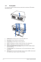
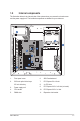
Table Of Contents
- Notices
- Safety information
- Chapter 1
- Chapter 3
- BIOS setup
- 3.1 BIOS Setup program
- 3.2 Main menu
- 3.3 Advanced menu
- 3.3.1 PCH-FW Configuration
- 3.3.2 Trusted Computing
- 3.3.3 CPU Configuration
- 3.3.4 Graphics Configuration
- 3.3.5 PCI Express Configuration
- 3.3.6 CSM Configuration
- 3.3.7 Super IO Configuration
- 3.3.8 Serial Console Redirection
- 3.3.9 SATA Configuration
- 3.3.10 Network Stack Configuration
- 3.3.11 USB Configuration
- 3.3.12 NVMe Configuration
- 3.3.13 Onboard Devices Configuration
- 3.3.14 Miscellaneous
- 3.3.15 APM Configuration
- 3.3.16 EzFlash
- 3.3.17 Watchdog Timer
- 3.4 Hardware Monitor menu
- 3.5 Security menu
- 3.6 Boot menu
- 3.7 Exit menu
- Appendix
- BIOS setup

1-4
Chapter 1: System introduction
1.3 Front panel
The front panel includes the optical drive bays, power button, reset button, LED indicators
and several I/O ports.
1. Cabinet cover. Use the key to lock or unlock the cabinet cover.
2. Reset button. Press this button to reset the system.
3. Power button. Press this button to turn the system on.
4. PLED. The LED lights up or blinks to indicate the status of the system power.
5. HLED. The LED lights up or blinks to indicate the status of the HDD.
6. 5.25-inch optical disk drive bay (empty). Allows you to install an additional optical
disk drive in this bay.
7. 3.5 inch drive bay. This 3.5 inch drive bay is for 3.5 inch hard disk drives / memory
card readers.
8. USB 2.0 ports. These Universal Serial Bus 2.0 ports connect to USB 2.0 devices such
as a mouse, printer, scanner, camera, PDA, and others.