
User Manual
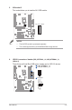


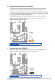
Table Of Contents
- Notices
- Safety information
- Chapter 1
- Chapter 3
- BIOS setup
- 3.1 BIOS Setup program
- 3.2 Main menu
- 3.3 Advanced menu
- 3.3.1 PCH-FW Configuration
- 3.3.2 Trusted Computing
- 3.3.3 CPU Configuration
- 3.3.4 Graphics Configuration
- 3.3.5 PCI Express Configuration
- 3.3.6 AMT Configuration
- 3.3.7 CSM Configuration
- 3.3.8 Super IO Configuration
- 3.3.9 Serial Console Redirection
- 3.3.10 SATA And RST Configuration
- 3.3.11 Network Stack Configuration
- 3.3.12 USB Configuration
- 3.3.13 NVMe Configuration
- 3.3.14 Onboard Devices Configuration
- 3.3.15 EZ-Flash
- 3.3.16 APM Configuration
- 3.3.17 Watchdog Timer
- 3.3.19 Miscellaneous
- 3.4 Hardware Monitor menu
- 3.5 Security menu
- 3.6 Boot menu
- 3.7 Exit menu
- Appendix
- BIOS setup

Chapter 2: Motherboard information
2-24
19. Digital audio connector (4-1 pin SPDIF_OUT)
This connector is for an additional Sony/Philips Digital Interface (S/PDIF)
port. Connect the S/PDIF Out module cable to this connector, then install the
module to a slot opening at the back of the system chassis.
PIN 1
SPDIF_OUT
+5V
SPDIFOUT
GND
NOTE: The SPDIF Out module is purchased separately.
Connector type
HEADER 1x4p, K2, 2.54mm pitch