
User Manual
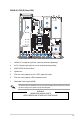
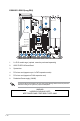
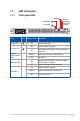
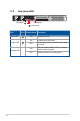
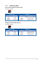
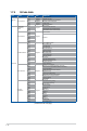
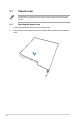
Table Of Contents
- Safety information
- Chapter 1: Product Introduction
- Chapter 2: Hardware Information
- 2.1 Chassis cover
- 2.2 Air duct
- 2.3 Central Processing Unit (CPU)
- 2.4 System memory
- 2.5 Storage devices
- 2.5.1 Installing an E1.S module (optional)
- 2.5.2 Removing an E1.S module (optional)
- 2.5.3 Installing an external 2.5” storage device (on selected models)
- 2.5.4 Removing an external 2.5” storage device (on selected models)
- 2.5.5 Installing an internal 2.5” storage device (optional on selected models)
- 2.5.6 Removing an internal 2.5” storage device (optional on selected models)
- 2.6 Expansion slot
- 2.7 Cable connections
- 2.8 Removable/optional components
- 2.9 Rail Kit Options
- Chapter 3: Motherboard Information
- Chapter 4: BIOS Setup
- 4.1 Managing and updating your BIOS
- 4.2 BIOS setup program
- 4.3 Main menu
- 4.4 Performance Tuning menu
- 4.5 Advanced menu
- 4.5.1 Trusted Computing
- 4.5.2 ACPI Settings
- 4.5.3 Redfish Host Interface Settings
- 4.5.4 Onboard LAN Configuration
- 4.5.5 UEFI Variables Protection
- 4.5.6 Serial Port Console Redirection
- 4.5.7 SIO Configuration
- 4.5.8 PCI Subsystem Settings
- 4.5.9 USB Configuration
- 4.5.10` Network Stack Configuration
- 4.5.11 NVMe Configuration
- 4.5.12 APM Configuration
- 4.5.13 Tls Auth Configuration
- 4.5.14 Intel(R) Virtual RAID on CPU
- 4.5.15 Third-party UEFI driver configurations
- 4.6 Platform Configuration menu
- 4.7 Socket Configuration menu
- 4.8 Security menu
- 4.9 Boot menu
- 4.10 Tool menu
- 4.11 Event Logs menu
- 4.12 Server Mgmt menu
- 4.13 Exit menu
- Appendix

1-12
LED Icon Display status Description
Power LED
ON System power ON
Location LED
ON Location switch is pressed
OFF
Normal status (Press the location switch again
to turn off)
Message LED -
ON
With the onboard ASMB11-iKVM: a hardware
monitor event is indicated
OFF System is normal; no incoming event
1.7.2 Rear panel LEDs
Location button
Power button Message LED