
User Manual
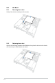
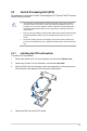
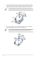
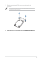
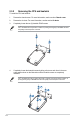
Table Of Contents
- Safety information
- Chapter 1: Product Introduction
- Chapter 2: Hardware Information
- 2.1 Chassis cover
- 2.2 Air duct
- 2.3 Central Processing Unit (CPU)
- 2.4 System memory
- 2.5 Storage devices
- 2.5.1 Installing an E1.S module (optional)
- 2.5.2 Removing an E1.S module (optional)
- 2.5.3 Installing an external 2.5” storage device (on selected models)
- 2.5.4 Removing an external 2.5” storage device (on selected models)
- 2.5.5 Installing an internal 2.5” storage device (optional on selected models)
- 2.5.6 Removing an internal 2.5” storage device (optional on selected models)
- 2.6 Expansion slot
- 2.7 Cable connections
- 2.8 Removable/optional components
- 2.9 Rail Kit Options
- Chapter 3: Motherboard Information
- Chapter 4: BIOS Setup
- 4.1 Managing and updating your BIOS
- 4.2 BIOS setup program
- 4.3 Main menu
- 4.4 Performance Tuning menu
- 4.5 Advanced menu
- 4.5.1 Trusted Computing
- 4.5.2 ACPI Settings
- 4.5.3 Redfish Host Interface Settings
- 4.5.4 Onboard LAN Configuration
- 4.5.5 UEFI Variables Protection
- 4.5.6 Serial Port Console Redirection
- 4.5.7 SIO Configuration
- 4.5.8 PCI Subsystem Settings
- 4.5.9 USB Configuration
- 4.5.10` Network Stack Configuration
- 4.5.11 NVMe Configuration
- 4.5.12 APM Configuration
- 4.5.13 Tls Auth Configuration
- 4.5.14 Intel(R) Virtual RAID on CPU
- 4.5.15 Third-party UEFI driver configurations
- 4.6 Platform Configuration menu
- 4.7 Socket Configuration menu
- 4.8 Security menu
- 4.9 Boot menu
- 4.10 Tool menu
- 4.11 Event Logs menu
- 4.12 Server Mgmt menu
- 4.13 Exit menu
- Appendix

2-6
5. Align the heatsink and CPU assembly to the CPU socket, and then place the heatsink
on top of the CPU socket (A). Push the lock latches outwards on all four corners of the
heatsink so that the heatsink and CPU assembly is secured to the CPU socket (B).
Ensure the triangle mark on the CPU is located in the same corner as the CPU socket.
6. Do two (2) clockwise turns on each of the heatsink screws in the cross order pattern
shown on the illustration until the heatsink screws are tightened.
Intel
®
recommends a using a torque driver with a T-30 bit and a torque value of 8 lbf-in to
prolong the longevity of all PEEK nuts after the quality of the load post is corrected.