
User Manual
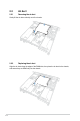
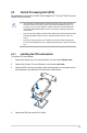
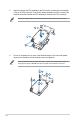
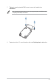
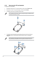
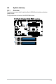
Table Of Contents
- Safety information
- Chapter 1: Product Introduction
- Chapter 2: Hardware Information
- 2.1 Chassis cover
- 2.2 Air duct
- 2.3 Central Processing Unit (CPU)
- 2.4 System memory
- 2.5 Storage devices
- 2.5.1 Installing an E1.S module (optional)
- 2.5.2 Removing an E1.S module (optional)
- 2.5.3 Installing an external 2.5” storage device (on selected models)
- 2.5.4 Removing an external 2.5” storage device (on selected models)
- 2.5.5 Installing an internal 2.5” storage device (optional on selected models)
- 2.5.6 Removing an internal 2.5” storage device (optional on selected models)
- 2.6 Expansion slot
- 2.7 Cable connections
- 2.8 Removable/optional components
- 2.9 Rail Kit Options
- Chapter 3: Motherboard Information
- Chapter 4: BIOS Setup
- 4.1 Managing and updating your BIOS
- 4.2 BIOS setup program
- 4.3 Main menu
- 4.4 Performance Tuning menu
- 4.5 Advanced menu
- 4.5.1 Trusted Computing
- 4.5.2 ACPI Settings
- 4.5.3 Redfish Host Interface Settings
- 4.5.4 Onboard LAN Configuration
- 4.5.5 UEFI Variables Protection
- 4.5.6 Serial Port Console Redirection
- 4.5.7 SIO Configuration
- 4.5.8 PCI Subsystem Settings
- 4.5.9 USB Configuration
- 4.5.10` Network Stack Configuration
- 4.5.11 NVMe Configuration
- 4.5.12 APM Configuration
- 4.5.13 Tls Auth Configuration
- 4.5.14 Intel(R) Virtual RAID on CPU
- 4.5.15 Third-party UEFI driver configurations
- 4.6 Platform Configuration menu
- 4.7 Socket Configuration menu
- 4.8 Security menu
- 4.9 Boot menu
- 4.10 Tool menu
- 4.11 Event Logs menu
- 4.12 Server Mgmt menu
- 4.13 Exit menu
- Appendix

2-8
2.3.2 Removing the CPU and heatsink
To install the CPU and heatsink:
1. Remove the chassis cover. For more information, see the section
Chassis cover
.
2. Remove the air ducts. For more information, see the section
Air ducts
.
3. Completely loosen the two (2) heatsink EVAC screws.
Intel
®
recommends a torque value of 6 lbf-in to prolong the longevity of all PEEK nuts after
the quality of the load post is corrected.
4. Completely loosen the heatsink screws by doing a few turns each time in the cross
order pattern shown on the illustration until the heatsink screws are completely
loosened
Intel
®
recommends a using a torque driver with a T-30 bit and a torque value of 8 lbf-in to
prolong the longevity of all PEEK nuts after the quality of the load post is corrected.